Category Timber Framing for the Rest of Us Rob Roy

More About Trusses

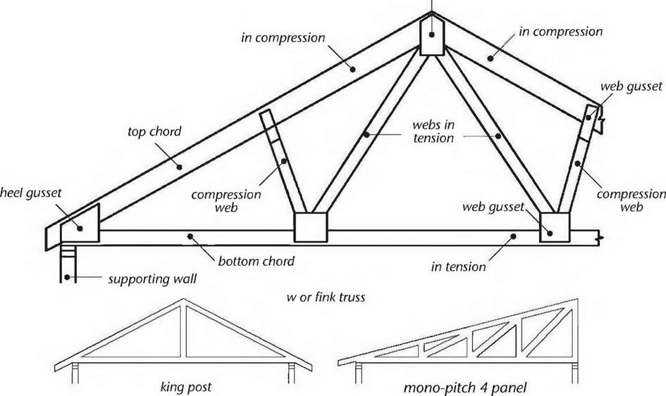
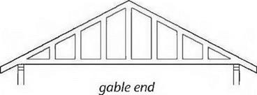
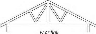
While trusses may be a little off the title subject of this book, they can be an easy, quick, and relatively economic method of building a roof, and they marry well to a strong one – or two-story post-and-beam framework. Trusses can be engineered for a variety of roof shapes, as seen in Fig. 4.44. They are great for garages, and are frequently used now in housing. Normally, there is no attic space in a trussed roof, but, as we have seen, the use of special “attic trusses” can yield quite a bit of upstairs space. Attic trusses will be heavier and more expensive, because the bottom chord of the truss has to be strong enough to support living space. But the extra cost is quite effective on a “square foot per dollar” basis.

Manufactured trusses are not particularly pretty, but, since they are normally hidden, this isn’t really a problem. Ceilings can be applied to the underside of the trusses, and you can install blanket or blown-in insulation in the spaces between. So, although you wont see any beautiful beams overhead, you can have a light-colored ceiling to brighten the whole building, and plenty of easy insulation options.

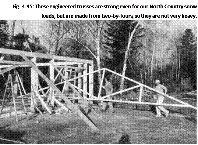
Подпись: Fig. 4.45: These engineered trusses are strong even for our North Country snow loads, but are made from two-by-foursr so they are not very heavy. It is important that trusses be stored vertically, or on a flat slab. Storing them on rough ground is the worst situation, as it puts all sorts of unwanted stresses on the truss plates, stresses that they are not meant to endure.

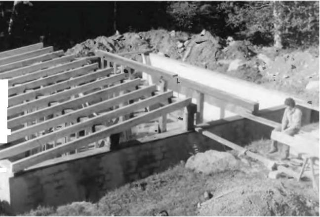
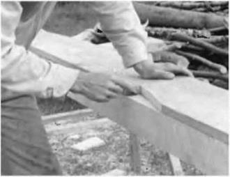
Lets have a last look (with Figures 4.45-4.51) at Chris Ryans garage project, where three people were able to install the 28-foot-long (8.5-meter-long) trusses without difficulty.

Roof Timber Framing for the Rest of Us

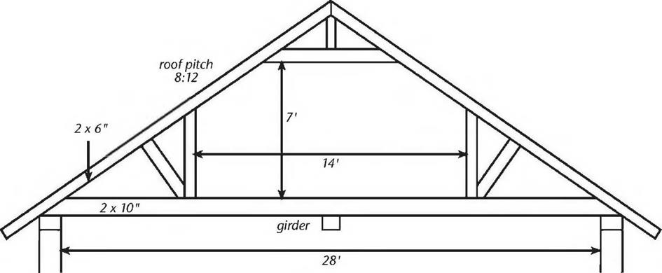
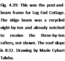
Подпись: Fig. 4.39: This was the post-and- beam frame for Log End Cottage. The ridge beam was a recycled eight-by-ten and already notched to receive the three-by-ten rafters, not shown. The roof slope is 8:12. Drawing by Marie Cyburt Taluba.image81Ridge beam. I cannot hide my love for a substantial ridge beam (also called, correctly but oddly, a ridgepole), and Гт not talking about the comparatively flimsy ridge “board” used by most stick-frame builders. No, I like something like the eight-by-ten at Log End Cottage (Fig. 4.39) or the ten-by-ten at Log End Cave (Fig. 4.40). Both of these houses were designed to support heavy earth roof loads, so the ridge beam spans were limited to about ten feet. Internal posts can be “free­standing,” where they are not in the way, or they can be incorporated into a wall and become integral with the floor plan. At Earthwood, we have two free-standing posts, one each story, and we learn to live and work around them. Another is built into a kitchen peninsula, containing countertop and cabinets beneath.

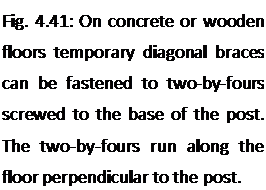
The post-supported ridge beam is strong. It transfers the load down in compression through the posts. As usual, brace the posts so that they are sturdy and plumb. I use screws to fasten the bracing material. Compared with pounding — and removing — nails, screwing imparts less stress to the frame. Sidewall posts can generally be braced to stakes in the ground, but on concrete brace as shown in Fig. 4.41.

Carefully measure and mark the rafter location along the ridge beam and also along the sidewall girts, according to your plan.

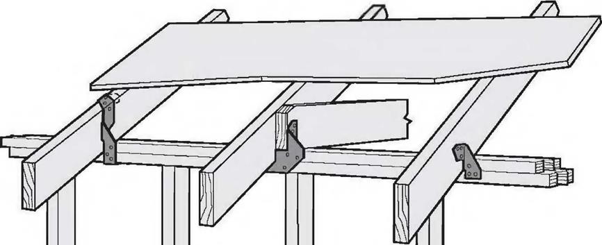
Rafters can be hung on the ridge beam with rafter hangers, but, as the hangers are adjustable for different pitches, they tend to be quite uncommon, as well as expensive.

Another method is to notch the rafters into the ridge beam. At Log End Cottage, we were fortunate that our recycled eight-by-ten ridge beam was already notched to receive the three – by-ten rafters that we recycled from the

same 19th century building in our local village.
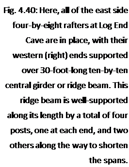
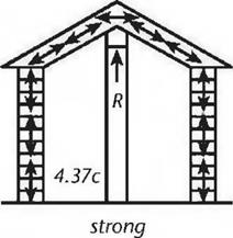
Подпись: Fig. 4.40: Here, all of the east side four-by-eight rafters at Log End Cave are in place, with their western (right) ends supported over 30-foot-long ten-by-ten central girder or ridge beam. This ridge beam is well-supported along its length by a total of four posts, one at each end, and two others along the way to shorten the spans. image82Yet another good method is to join a corresponding pair of rafters over the ridge beam, as we did at Log End Cave. In this case, truss plates on each side of the four-by-eights, at the ridge, can tie each pair of rafters together, or a metal strap can be installed over the top of the rafters, which also serves to tie the rafters to each other. This is important; whatever method of fastening you choose, the rafters must be positively fastened to the ridge beam or to each other to prevent a lateral thrust on the walls. Explanation: The ridge beam cannot move in a downward direction because of the “reactionary load” of the posts, as we saw in Fig. 4.37c. If the

І

rafters are firmly fastened at the ridge,

І »Jtheir top ends cannot move downward

Iw % dpi either. If the tops of the rafters cannot

move downwards, the lower parts of the rafters cannot splay the sidewalls outwards.
Подпись: Fig. 4.41: On concrete or wooden floors temporary diagonal braces can be fastened to two-by-fours screwed to the base of the post. The two-by-fours run along the floor perpendicular to the post.Fastening rafters to sidewalls using birdsmouths. There are various ways of tying rafters to sidewalls, and the choices may vary depending on roof pitch. One of the most common is the use of “birdsmouths” cut into the rafter. A notch is cut into the rafter so that the rafter bears down flat upon the doubled top plate of stick framing, or upon the girt in heavy timber framing. (The notch resembles a birds open beak, thus the term.) The birdsmouthing method, in combination with toe-nailing or the use of metal right angle fasteners, is a good way to transfer load down to the wall with roof slopes of 2:12 to 12:12. But there are drawbacks:

1. The rafter is weakened when you
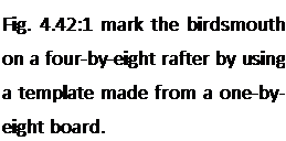
Подпись: Fig. 4.42:1 mark the birdsmouth on a four-by-eight rafter by using a template made from a one-by- eight board.image83cut into its cross section in this way, particularly on shear, which is a function of cross – sectional area of the timber.

This weakness is mostly in the overhang.

2. It is very easy to make a mistake and cut the birdsmouth at the wrong location. Either the piece is wasted, or there will be some other problem with the build quality if you try to use a miscut member. One would like to think that each piece should be exactly the same, and that a template that works well for one rafter will work for all. In the best of all possible worlds, this is true, but combine rough-cut material with a first­time owner-builder, and the chances of success with a template are pretty slim. By all means, use a template for marking the depth and shape of the cut according to the chosen pitch, but be ready to change the distance spacing of the birdsmouth from the ridge according to actual (not theoretical) measurements. I used a template at Log End Cave (Fig. 4.42), but always checked my measurements for each rafter, sliding the template a little bit, as needed, to accommodate discrepancies.

3. Rafters with birdsmouths in them are not much use for recycling when another builder attempts to recycle your materials two hundred years from now.

4. The cuts are moderately difficult on heavy timbers, such as five-by-tens, something were trying to avoid with timber framing for the rest of us.

You may have guessed that I’m not a big fan of birdsmouths, although I used them on the three-by-ten rafters at Log End Cottage in 1975. I remember that it was a slow tedious process, for reasons already stated in Drawback 2 above. But, in fairness, it must be stated that birdsmouthing is the method that most carpenters use.

Metal connectors are not commonly made for replacing birdsmouthing, and the reason for this may be that connectors would have to be made for a variety of pitches. However, metal tie-down connectors for use in special wind or seismic

image84

L-Ur

image85

Fig. 4.43: A variety of tie-down

connectors. Illustration courtesy of areas are very common and will be required by code in those areas. They can be

Simpson Strong-Tie Co., Inc. used in combination with birdsmouths. Examples of such tie-down connectors

are shown in Fig. 4.43.

Fastening rafters to sidewalls using shims. With shallow-sloped roofs, — say 1:12 to 2:12 — I avoid birdsmouths altogether in favor of shimming with wooden shingles. These shingles, usually white cedar, have a taper to them of about one – quarter in twelve (0.25:12). So four shingles, laid one upon another, yields a 1:12- slope roof, which I like with plank-and-beam earth roofs. The use of shingles with rough-cut timbers has these advantages:

1. It is easy to accommodate different depth dimensions of the rafters with shims. Extra shims can raise “low” rafters so that tops of all are in the same plane, greatly facilitating the installation of planking or plywood.

2. Shimming is much easier to do than birdsmouthing, and yet is still strong, because of the great friction between the rough wood shingles and rough – cut timbers.

3. The use of shims does not weaken the rafters in shear, particularly important with heavy earth roof loads.

ridge gusset

image86


image88

Fig. 4.44: Trusses. Top: Typical W truss, showing its parts and how they work. Bottom: Various truss designs satisfy different needs. Here are just four common ones. Reproduced from Residential Framing by William P. Spence (©1993 by William P. Spence) with permission from Sterling Publishing Co., Inc., NY, NY 10016.


image87

4. A place of common error is eliminated, saving the heartbreak of a wasted timber. (Hey, it’s heartbreak for me, known for squeezing a quarter until the eagle screeches.)

After the rafters are all shimmed and placed in the right locations (which you’ve already marked with pencil on the girt), you can use toenails or right-angle plates to tie them to the wall. Remember that in certain areas, code may require metal straps or metal tie-downs to tie the roof structure to the wall structure, part of the continuous load path already discussed.
Roof Systems

There are basically two different roof-support systems that are appropriate for use with timber framing. Most timber framers continue on with additional timber framing, and I have done this, as well, at Log End Cottage, Log End Cave, and Earthwood, by using methods described in this book. The other support system that should be considered carefully is the truss-supported roof, like the garage at Earthwood and the one that Chris built.

Is one system better than the other? Not necessarily. There are pros and cons for each.

i. Engineering. Trusses are normally designed and built by professionals.

I’m not saying that owner-builders have never done it, and successfully, but, like mixing one’s own concrete, it is hardly worth the effort for the money saved. Engineering is crucial. You would need to use a standard truss design that happens to suit the dimensions and purpose of your building, or have the trusses professionally engineered. Then you’d need to create a large template, such as on a barn floor, to actually fasten the various chords together with truss plates. Purchased trusses are not that

image80

expensive, and the manufacturers know how to design a truss for your Fig. 4.38: Richard Flatau’s attic

application. trusses looked something like this.

The engineering of a timber-framed roof is a bit more basic, and timber frame designs tend to be on the over-built side, anyway. With a rafter system, you can consult span tables to find appropriate timber size.

Still, unless you are following a tried and proven plan, you should have your entire timber-frame plan checked by a structural engineer. And strong jointing, both at the top and the bottom of the rafter, is critical.

2. Upstairs space. With timber framing, it is, perhaps, a little easier to create useful space under the roof, although there is a truss design, called “attic trusses” which can afford some space upstairs, usually a little less than half of the entire area of the ceiling below. Richard Flatau used attic trusses with his post-and-beam cordwood home in Merrill, Wisconsin. The company that engineered, built, and delivered the trusses also put them up onto the girts. Their delivery truck has a boom built onto it for the purpose. Richard hired a contractor friend experienced in truss work and enlisted a couple of other friends as “grunts,” and the 20 heavy trusses were installed in just two hours. Richard says that the trusses enclose 560 square feet (52 square meters) of extra living space upstairs, including two bedrooms, a play area, ample storage, and a half bath. See Fig. 4.38.

3. Ease of construction. By the time the girts are in place, timber-framing the roof structure will be an extension of using many of the same

techniques with which the builder is already familiar, although there will be a few new ones. Trusses are an entirely different kettle of fish, but installing trusses is not that difficult, particularly if you follow Richard Flatau’s example and hire one person with experience to tell you and your other helpers what to do.

Trusses can be installed with or without the use of a crane. Chris Ryan simply had his garage trusses delivered to site, and he and two friends were able to hang them upside down between the parallel sidewalls by themselves. (Fig. 4.46 on page 97). Later, with a man at the top of each side wall, a third person with a long pole would “flip” a truss upright, and then, from a ladder, help the team space and brace the truss into position. It is really important that the trusses be square on the girt system, parallel to each other, and exactly at the planned regular spacing, usually 16 or 24 inches on center.

Using a framing square, you should mark the top of each girt, showing each edge of each truss. Make sure the spacing comes out right on both sides. Spacing is critical if you are planning to nail plywood on top, or sheetrock ceilings to the underside of the trusses. Squareness and plumb are both part of the all-important build quality.

On balance, and assuming that you find someone with experience to help, I’d say that trusses are probably quicker and easier than timber framing.

Incidentally, traditional timber framers often create what can be described as timber-framed trusses, which they raise like bents on the day of the timber raising, as we saw back in Fig. 2.17. Conventional timber framers — the rest of us — usually install each member individually.

4. Cost. Richard Flatau says that his attic trusses actually cost $800 less (1979 prices) than the cost of a conventional “stick-built” roof. The total cost of his 20 trusses, delivered and placed on the girts, was $1,400 in 1979. These were large, heavy trusses, suitable to support floor loads upstairs. I think it is safe to just about triple the cost of those trusses today. Our garage trusses span 24 feet and have two-foot overhangs each side, and cost us $58 each in 1998. But Richard’s trusses were made from two-by-sixes and two – by-tens, while all parts of our trusses are two-by-fours. It is difficult to compare truss cost to timber-frame cost, as the cost of the timbers themselves varies so widely from one project to another, depending on

how the timbers were procured. While trusses may be cheaper than conventional stick-frame construction (when labor is factored in), they are certainly more expensive than framing with homegrown timbers.

Build Quality, Gravity and Inertia

Note that in all of the joining methods described above, the beams are not diminished in cross-section, so full shear and bending strength is maintained.

1 cannot over-emphasize the importance of maintaining a good standard of “build quality.” One member should bear flat on another, without wobbling. The end of a beam should bear at least four inches on the supporting post or beam below, if possible. Timbers should be vertically plumb and horizontally level. The design should assure that the line of thrust is always transferred directly in compression from one member to another.

By paying attention to the build quality, you enlist a great ally, which is the force of gravity. Gravity is very precise: it always works exactly vertically (which enables a bubble-level to function properly, by the way). And it is reliable; that is to say, it is working for you every morning when you wake up, and through the night as well.

Gravity and its close relative inertia are very important parts of all heavy timber-framed structures. Earth-roofed structures help even more in this regard. Our roof at Earthwood weighs between 6о and 120 tons, depending on moisture and snow loads. Even at the low end (dry, no snow), the 6o-ton load has a tremendous inertia. The seven load-bearing eight-by-eight posts downstairs are not even pinned to the floor; with at least three tons on each post, they aren’t going anywhere. (I know, three times seven tons is only 21 tons. The external walls and central masonry column support the rest.) Now, I don’t advise not pinning the posts to the floor — “Do as I say, not as I do!” — but I just thought you might find our experience interesting.

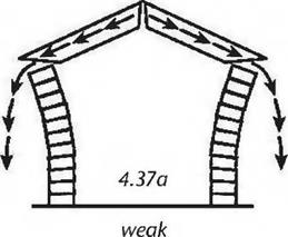
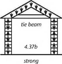
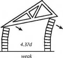
Gravity can work against you, too. You have probably seen lots of diagrams like Fig. 4.37. These drawings depict freestanding cordwood walls, which are strong on compression and weak on tension. Using cordwood exaggerates the effect of the stresses a bit, but helps make the point. The same sorts of compression and tension forces are at play in a post-and-beam wall. They may be less obvious, but they need to be attended to for the same reasons.

In Fig. 4.37a, the roof load wants to follow gravity’s path, but the angle of the rigid rafters transfers the downward thrust to an outward thrust on the walls, and the building falls down. This would be an excellent example of egregiously bad build quality. In Fig. 4.37b, the tie beam has a tensile strength sufficient to offset

image76image77image78image79the outward thrust. Another way of thinking about it is that the tie beam turns the roof structure into a giant rigid triangle, a triangle with — and this is important — a flat bottom. Gravity’s downward thrust is carried straight down onto the vertical walls. This is how trusses work.
In Fig. 4.37c, rafters are well-tied to a ridge beam, which, in turn, is supported by posts. If the tops of the rafters can’t go down — and they can’t because of the reactionary load “R” provided by the posts — then they cannot put an outward thrust on the walls.

The importance of level and plumb is illustrated in Fig. 4.3yd. Here, we have a nice rigid triangular truss, but the bottom chord of the truss, which is inclined, alters the vertical line of thrust. This resultant vector of force places unacceptable stresses on the walls, as shown. Working with gravity, and not against it, is always a good idea. In this example, if the walls were the same height, and the bottom chord was horizontal, the line of thrust would be straight down onto the walls, which — being strong on compression — would then provide the required reactionary load.

Build quality, gravity, and inertia can be important allies… or deadly enemies.

Timber Framing Hybrid

Let’s return to Chris Ryan’s garage to see a method of making girts from a pair of two-by-eights instead of a single eight-by-eight. Chris had seen that Russell Pray used a similar method on the gables ends of the garage at Earthwood and he modified Russell’s method slightly, so that he could use doubled two-by-eights all around the building at the girt level. The advantages were twofold: i) he was able to save on cost, as two two-by-eights are only half as much wood as a single eight – by-eight. And, 2) Chris could install the two-by-eights working alone, whereas hefting long heavy eight-by-eight girts up over the eight-foot-high posts would require a crew of helpers.

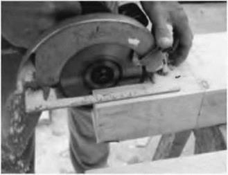
This hybrid method of timber framing is very strong. It is not quite traditional timber framing, as it does use some metal fasteners and the joints are easy to make with a circular saw and a chisel. But it requires shaping the top of posts. “Timber framing for the rest of us” does not mean that you have to be afraid of a little timber shaping. I always get a lot of satisfaction when I take the time to make a simple wood joint, even the relatively easy kind described here. Figs. 4.29 through 4.36 will take you through the simple process.

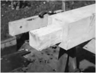
image68image69image70image71Fig. 4.29: The goal is to support a doubled system of continuous full-sized two – by-eights all around the building at the girt level. One set will be installed flush with the posts on the inside, and the other set will be flush with the posts on the outside. To accomplish this, all that is needed is to remove some of the wood at the top of the post to create a notch — or "shoulder" — upon which the two-by­eight will be supported. Here, Chris works on the top of a four-by-eight door frame. He marks a notch eight inches (20.3 centimeters) long and two inches (5.1 centimeters) from each edge of the eight-inch (20.3-centimeter)-wide surface of the post. He cuts as deeply as he can with his circular saw, then turns the timber over and repeats from the other side. Then he makes the transverse cut across the four-inch dimension. This one can be done at the full two-inch depth.
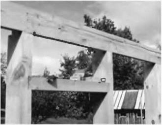
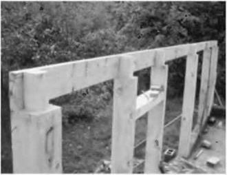
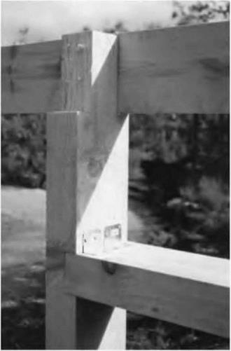
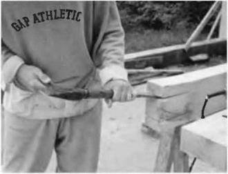
Fig. 4.30: The two longer cuts meet, but not quite all the way, because of the circular shape of the saw blade. However, the wood is easily snapped off with a chisel.

Fig. 4.31: The four eight-by-eight corner posts have two inches of wood removed all the way around the top of the post, down to a shoulder eight inches from the top. Again, this is accomplished by combining saw cuts with chisel work. All of the post tops for the garage are shaped in this way before they are stood up and plumbed, but sidewall posts need shoulders on just the inner and outer sides, not all four.

Fig. 4.32: Here, the three major eight-by-eight posts along the sidewall are in place. The middle post is set to the stretched nylon mason’s line. Corner posts are shaped as in the previous picture, Fig. 4.31, and the middle eight-by-eight has had just its sides trimmed back two inches to receive the two-by-eights, butted together on the shoulder.

Fig. 4.33: Two outside two-by-eights, each 14 feet long, meet over the middle post, which is another eight-by-eight. It is the fourth one from the left. The other two posts, with a door lintel notched in near the top, are made of four-by-eights, as shown in Figs. 4.34 and 4.35. This view shows clearly where the inner two-by – eight member of this girt system will bear on the notched posts.

image72

Fig. 4.34: This detail shows the notching of the door lintel into the doorposts. The four-inch-thick lintel is set about 1-1/2 inches (3.8 centimeters) into the four-inch dimension of the posts. Four-inch (10.1 – centimeter) screws driven from the side of the post into the lintel could hold it in place, as could four-inch (20-penny) nails. Screws have less impact on the frame than nails, and they are easily removed.

Fig. 4.35, far right: This is the other side of Fig. 4.34. Chris used right-angle galvanized metal connectors to hold the lintel fast to the door posts.

Fig. 4.36: The two-by-eights at the gable ends give stability to the entire rectilinear frame of the garage. One of the two-by-eights needs to be attached with a mechanical fastener or toenails. The little piece replaces a chiseled cut from Fig. 4.31 that really did not have to be removed in the first place. If this was an error, it was a very minor one, and gave Chris the option of fastening the doubled two-by-eights in two different ways. Visualization is important in planning even simple joints. Draw everything out on paper first, erasing and redrawing lines

image73image74image75"until it makes sense.

When Two Beams Meet Over a Post

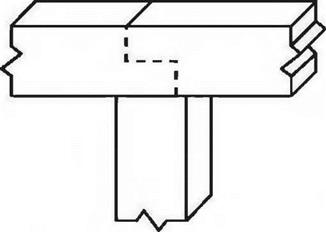
Where any two beams meet over a post, there are many ways, short of matrimony, to join them together. Traditional timber framers have a variety of joints to use in this situation, including an assortment of “scarf” and “dovetail” joints — these take practice — and half-lap joints, as in Fig. 4.14. Lap joints are not too difficult to make with common tools, and you may like to have a go at them. A drawback, however, is that shear strength of the beam is diminished when it is cut half way through. In fact, weakening of structural members is almost always the case with any traditional joint. Another example of this would be an eight-by-eight-inch beam with a tenon of two-by-eight-inch cross-section carved into its end for insertion into the mortise of an adjacent post. Shear strength is reduced by 75 percent in this case. This is not a problem for timber framers because the structures are so extraordinarily over-built in the first place, and good tight-fitting joints and pegs go a long ways towards promoting strong joints.

The rest of us have several choices:

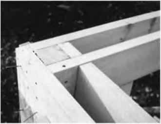
1. Truss plates on the top. I used this method to join the tops of the post-supported octagonal ring beam at Earthwood. This octagon, halfway between the center pillar and the external walls, cuts the floor joist spans in half on the first floor, and the roof rafter span in half on the second story. When you cut its span in half, you make a beam — remember? — four times stronger on bending. The truss plates are out of the way and out of view, so this was an effective solution. See Fig. 4.23.

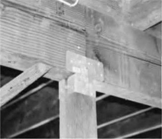
2. Подпись: Fig. 4.23, above: Truss plates tie the girders together at the octagonal internal frame at Earthwood. This frame cuts the radial floor joist spans in half.image64Подпись: Fig. 4.24, right: Two four-by-ten (10.1- by 25.4-centimeter) girders meet over a four-by-four post, the joint made strong by the use of a pair of galvanized metal connectors.image65Toe-nailing or toe-screwing from the top of one horizontal timber, diagonally into the end of the adjacent member. Not quite as rigid as the truss plate
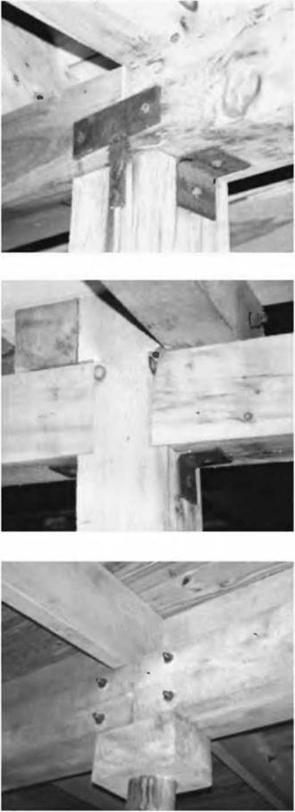
method, but quite strong just the same, and useful where truss plates will either be seen or be in the way of fastening another post or beam.

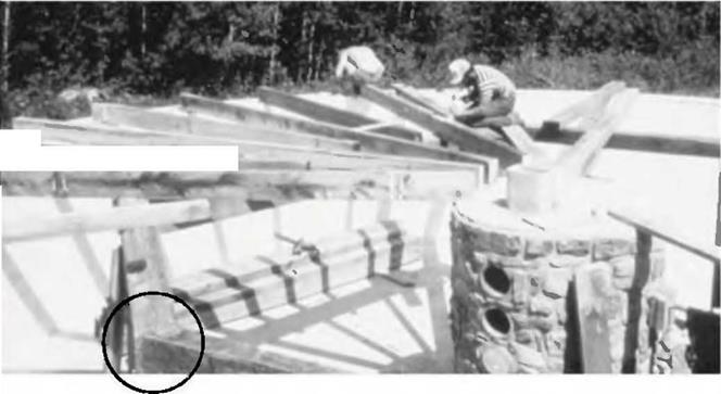
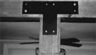
3. T-straps. (Figs. 4.13, 4.24 and 4.25) You can buy a variety of these at the building supply, and their esthetic qualities vary. My friend Steve in Hawaii used the off-the-shelf connectors shown in Fig. 4.24 to join two four-by-ten girders over a four-by-four post. This pair of connectors does everything in one shot: it connects the two girders, and connects the girders to the post. It is not beautiful, but the detail is down in the garage, under the living space, so esthetics matter less. Fsthetically, the best T – straps I have seen are homemade as shown in Fig. 4.13 and use lag screws instead of nails. Several acquaintances have made their own attractive T – straps from one-eighth-inch stock or better, and painted them black. Whenever this method is used, full strength comes from using them on both sides of the joint. Some manufacturers make decorative heavy strap connectors, too.

image66Подпись:

When Two Beams Meet Over a Post

4.28.

Maintain a whole toolbox of these joining methods and have them all available for use as needed. Sometimes one method won’t work but another will. Redundancy of methods is not necessarily a bad thing, either. With large projects, in fact, good engineers deliberately incorporate structural redundancy into buildings to allow loads to be carried by more than one path.

Toe-nailing and Toe-screwing

Nails, when they became cheap, replaced dowels, doveta Is, and mortise-and-tenon joints. Most nailing is called surface nailing: driving a nail straight through one board in order to fasten it to another. This is the way roofing planks and plywood are installed, as well as wooden siding.

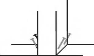
But one of the most valuable skills in timber framing for the rest of us is to learn how to toenail properly. A toenail (in carpentry) is a nail driven at an angle that allows us to join one timber to another where they meet at right angles. It is a fairly strong method of nailing, because toenails are always installed opposite each other, as in Fig. 4.21. Some of the nails will always provide shear strength, no matter which way a timber is forced. Toe­nails don’t pull out easily, as you will discover when you make a mistake, and have to take your own work apart.

Toenails should be installed at about a 60-degree angle, as shown in the illustration. With two-by framing, an 8-penny (2.5-inch) toenail is started about three – quarters-inch (1.9 centimeters) up the upright. But with heavy timbers, I tend to use a larger nail, such as a 16- penny (3.5-inch) nail, and start it an inch or even 1.25- inch (3.2 centimeters) up the side of the post. With the 60-degree angle, you will still get plenty of purchase into the wood below.

The "law of the toenail" says that you will move the base of the post or beam in the direction in which you are striking. You can avoid this by marking the post in its correct position with a pencil and then starting one of the toenails until it grabs the substrate. You can drive it until the post begins to move, then stop. Install the opposite toenail as a reactionary thrust. It will move the post back into the correct position. By working on one toenail, then its opposite, you can set the post firmly, right where it belongs.

You can lessen the chance of splitting wood while toe-nailing if, first, you hit the pointy end of a nail quite stiffly with a hammer while its head bears against something hard, such as concrete. This will dull the point. A pointed nail tends to spread the fibers and split the wood, but a blunt nail will simply puncture the wood grain as it penetrates: no split. With large nails, pre-drilling the angle will also reduce the chance of splitting wood and make the nail easier to install.

As the years go by, I use nails less and screws more. Screws have the advantage of being removable. Toe­screwing is my term for using a screw instead of a nail in a toe-nailing situation. With large (3.5- to 4-inch or 10.1 centimeter) deck screws, drill a small pilot hole first to lessen the chance of splitting. Use an electric drill to install these screws, not a screwdriver. Robertson screws — the ones with the little indented squares in the head — drive more positively than Phillips or slotted screws and the heads are less likely to get mangled by the driving bit.

For the remainder of this book, the terms "toenail" or "toenailing" also implies the optional use of screws.

Toenailing can also be used to fasten any beam over a post. The toenails (or screws) are driven upward through the post into the beam. See the sidebar on the facing page. The “law of the toenail” is particularly strong In this situation, and screws give a little more control than nails.

Another way to hold the beam fast over a post as by the use of truss plates, as shown in Fig. 4.22a, and you really need to place one each side of the wall to get the proper strength. The downside of this method is that the truss plates will often be in view in this application, and they are not particularly nice looking. You can beat this by making your own heavy (one-eighth-inch or 3.2 millimeter) pieces, drilling holes in them, and installing them as in Fig. 4.22b, with, say, two one-quarter-inch by 3- inch (0.6- by 7.6-centimeter) lag screws into each member (four per plate, each side of the joint.) Paint them whatever color tickles you. But black is nice.

Yet another post-to-beam fastening method is shown in Fig. 4.22c, in which the metal can be hidden inside of an infilled wall. Here, right-angle fasteners, commonly available at any hardware store, are used instead of toenails. These are like ordinary truss plates, but bent in the middle to form a right-angle. In a pinch, I have bent truss plates into right angles for the purpose, as in Fig. 4.35. Use four – penny (4d) nails, which are one-and-a-half inches long. You don’t have to put a nail in every hole provided. I generally use about half the holes, as long as this is at least five in number, more with larger plates or right-angle fasteners.

Fastening the Girt to the Top of the Posts

Before attempting to lift a heavy girt (or girding beam) to the top of posts, make sure that the posts are vertically plumb — check two adjacent sides with the plumbing bubble on your level — and that all the posts are supported with sturdy bracing, as already discussed. Make sure that the posts are all the same — and the correct — height (see Post Height earlier in this chapter), and that their tops are square, which, in this case, translates to flat.

Based on your plan, the girts might be supported by two, three, or even more posts. A post at each end supports the 16-foot-long (4.9-meter-long) eight-by – eight girts in our garage, with a third post supporting the middle. The posts need to be the same height so that the girt will rest nicely on all three.

Russell Pray, a contractor friend, actually erected our entire garage framework for us while we were conducting workshops in British Columbia. He used a beam-cutting saw (very expensive!) to get nice square cuts on the eight-by-eight and four-by-eight posts and the eight-by-eight girts. To fasten the girts to the top of the posts, he used a heavy-duty electric drill to install ten-inch TimberLok™[7] screws down through the eight-inch girt and into the tops of the posts, two screws at each post. Lots of temporary diagonal bracing protected the entire frame against racking and provided stability while the 30-foot-long (9.1-meter-long) trusses were installed over the girts. Where two girts butt together over the post halfway along the sidewalls, shorter toe screws at the tops of the girts help tie one to the other.

Fastening the Girt to the Top of the Posts

Fig. 4.21: Install toe-nails (or screws) at about a 60-degree angle. As it is driven in, the toenail on the right will drive the post to the left. See sidebar text entitled Toe-nailing and Toe-screwing on the following page.


image60

Wind Can be a Serious Problem

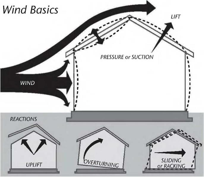
Подпись: Fig. 4.16: Fiere, graphically, are the basic ways that wind can affect a structure. Illustration courtesy of Simpson Strong-Tie Co., Inc.
image52

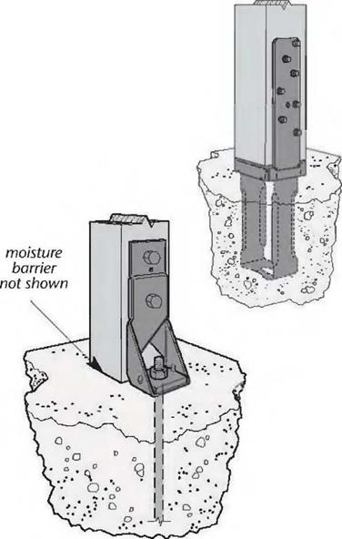
Подпись: 8"x8"Подпись:image53In certain areas of the country like the southern U. S. Gulf Coast, Hawaii, “Tornado Alley,” coastal Alaska, and other areas, code demands a more positive tie-down mechanism than the positioning pin and gravity technique that I employ in northern New York. Fortunately, several manufacturers make a variety of anchoring fasteners whose purpose is to tie the base of the posts to foundations. Three companies are listed in Appendix C. One of the leaders in the field is Simpson Strong-Tie Co., Inc. In their High-Wind-Resistant Construction Product Selection Guide (catalog C-HW02, November 1, 2002), on page 4, they say: “Newer building codes such as the International Building Code (IBC), the International Residential Code (IRC), and the Florida Building Code (FBC),
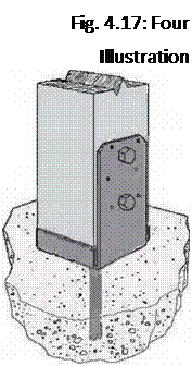
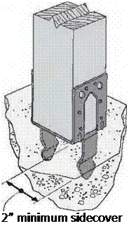
Подпись: different post bases, courtesy of Simpson Strong-Tie Co., Inc.Подпись: Fig. 4.17: Four Illustration Подпись: 2” minimum sidecover image56"have had a profound effect on the way wind design is performed/’ The same publication gives this concise overview of how strong winds affect buildings: During a thunderstorm, blizzard, hurricane, or tornado, the force of the wind on a house works in three ways:
1. As it flows over the roof the wind creates a strong lifting effect (uplift).

2. It exerts horizontal pressure which tries to overturn the structure.

3. If overturning is resisted, the wind pressure tries to slide the structure off of the foundation or to rack the walls.

Be extremely careful working around or under heavy timbers that have not yet been firmly tied to each other and diagonally braced to the ground, foundation, or floor. Avoid timber framing on windy days.

Tying Posts and Sills to the Foundation

While codes in areas of severe wind potential are concerned with all the structural components, up to and including tying roof trusses and rafters down to the

top plate, the first building require­ment will be to tie the posts to the foundation. Simpson makes a variety of post and column bases for the purpose, and some examples are shown in Fig. 4.17, reprinted by kind permission from Simpson. Other companies make similar products. Note that some of these post bases can be fastened to anchor bolts set in the concrete (or in grouted concrete block cores), while others involve embedding the lower part of the base into the concrete. With a poured slab or footing, these anchors will have to be installed accurately at the time of the pour. Make sure that you understand how the base works before you set it up in the concrete, and be careful that the part upon which the post rests is flush with the top of the
foundation or a tiny bit above it. An advantage of the fastener styles that make use of anchor bolts or pins is that the base-support piece is snugged up to the foundation by tightening a hex­headed nut. This system seems a little more forgiving of error.

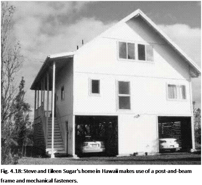
Подпись: Fig. 4.18: Steve and Eileen Sugar's home in Hawaii makes use of a post-and-beam frame and mechanical fasteners. Подпись: Fig. 4.19: The girder is strapped to a concrete-filled column.image58While visiting Hawaii’s Big Island in 2003, I noticed that a lot of people make use of tie-down connectors from the foundation right through to the roof. The Simpson Strong-Tie folks call this a “continuous load transfer path.” Steve Sugar says that his building inspector is quite insistent on that, because Hawaii can bare the brunt of some pretty powerful winds. Steve and Eileen Sugar’s house, seen in Fig. 4.18, is built up on twenty or so four-by-four posts, each married to heavy concrete bases as shown in Fig. 4.1 at the beginning of the chapter. The metal fasteners were cast in place. The living area is all above the garage space, a protection in case of flooding (in a region of 200-plus inches (5.08 meters) of rain per year) or tsunami (tidal waves) that occasionally hit the coast.
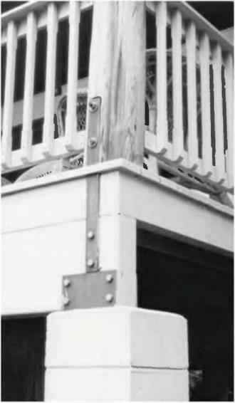
On the other side of Hawaii, Terry, another owner-builder, also put his living space eight feet up, and for similar reasons. A self-reliant mango farmer, Terry used strong homemade metal fasteners to tie his main girders to the seven-foot pillars made from concrete-filled hollow-core chimney

blocks. These blocks, which come in 16- by іб-inch (and other) sizes, are very handy for building a deck up off of the ground. Filling the blocks with concrete and vertical rebar makes a strong pillar, and the U-shaped plate assembly can be set into the concrete of the last core. We see just the exposed part of this assembly in Fig. 4.19. Note, also, that the girder is tied to the main corner post column with a strong metal strap.

Подпись:We’ll return to Hawaii later to see how floor girders and roof rafters were fastened down to posts.

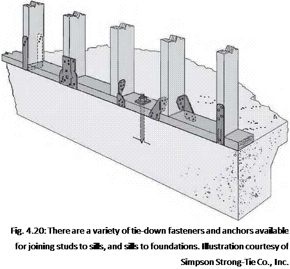
Specialty fasteners are also available for tying sill plates down to foundations, although regular anchor bolts, as already described, are very strong. In high-wind areas, your tie-down methods will have to agree with local code or the local code­enforcement officer, who may have some discretion. Although Timber Framing for the Rest of Us is concerned with post-and-beam framing, not conventional balloon framing, Fig. 4.20 may be of interest to show that fasteners are available for virtually every kind of wood-to-wood (or wood-to-masonry) situation.

About Metal Fasteners

Several companies manufacture metal fasteners for a variety of wood-to-wood and wood-to-foundation applications. Since 1975, I have done a lot of timber framing without using these fasteners (except for truss plates), and I will share my techniques in these pages. But manufactured metal fasteners can make life easier, the building inspector happier, and improve the strength of the structure, so they are a valuable option. There are hundreds of different connectors available, and, while reading this book is a good introduction, I cannot cover all of the products in this relatively small volume. Therefore, you should also 1) go to your local hardware or building supply store and look at what’s readily available in your area (see Fig. 4.12) and 2) contact the companies by mail or through the Internet and look at their catalogs or web pages. There is an engineered code-compatible connector for practically every imaginable situation.

If there is a downside to these manufactured connectors and fasteners, it is that they are made mostly for lumber of finished dimensions. In the mechanical fastener industry, a four – by-four is almost always 3V2 inches by 3V2 inches and a six-by-six is 5V2 inches by 5У2 inches. However, companies do manufacture full-sized connectors for rough-cut posts, and also some joist hangers for rough-cut material. Simpson Strong-Tie Co, Inc., for example, has joist hangers for all depths (up to 14 inches or 35.6 centimeters) for rough-cut two-bys, four-bys, and six-bys, but not for three – bys and five-bys. One local building supply sells USP joist hangers that will work with full-sized five-by-tens.

Подпись: Fig. 4.12: There is a great little hardware store in Pahoa, Hawaii, with quite a selection of metal connectors. Practically all new construction in Hawaii makes use of these connectors, because of severe expected wind loads. Still, over 90 percent of the fasteners in a catalog are for dressed lumber, so you will have to wade carefully through the catalogs to find what you need. You can also call the companies with specific requests, although specialty items will be expensive. Plan ahead for your connectors, so that you have them when you need them. The cost of standard connectors and fasteners is very reasonable, with many simple strap and plate connectors selling for fifty cents or less.
Another potential downside of galvanized metal fasteners is that they are not particularly attractive. However, they are usually installed where they are not seen, or, at any rate, not seen for very long. Also, Simpson Strong-Tie makes a few heavy (12-gauge) ornamental connectors with textured fiat black paint, including straps, T-straps, right angles, and a variety of heavy joist hangers. These are quite a bit more expensive than the standard fare, but can justify their cost if only a few are needed in exposed locations.

Post supports, for example, can be installed so that the metal parts will be hidden in the thickness of whatever infilling material is chosen. Similarly, right angle connectors, used, for example, where a girt is supported on a post, can be hidden in the infilling.

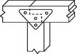
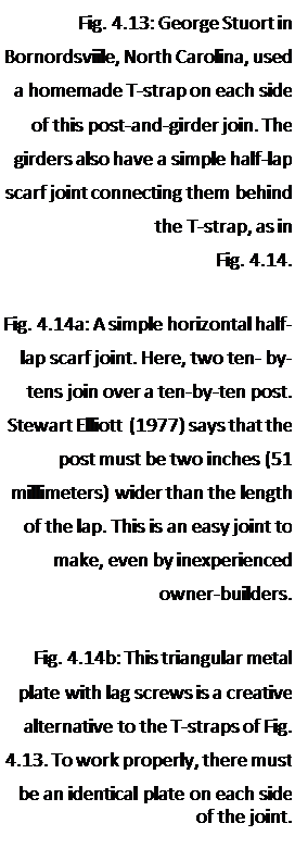
Подпись: !Подпись:Подпись: Fig. 4.13: George Stuort in Bornordsviile, North Carolina, used a homemade T-strap on each side of this post-and-girder join. The girders also have a simple half-lap scarf joint connecting them behind the T-strap, as in Fig. 4.14. Fig. 4.14a: A simple horizontal half-lap scarf joint. Here, two ten- by-tens join over a ten-by-ten post. Stewart Elliott (1977) says that the post must be two inches (51 millimeters) wider than the length of the lap. This is an easy joint to make, even by inexperienced owner-builders. Fig. 4.14b: This triangular metal plate with lag screws is a creative alternative to the T-straps of Fig. 4.13. To work properly, there must be an identical plate on each side of the joint. image49image50image51First floor joists are almost always hidden, but exposed ceiling joists or roof rafters are not.

An option to commercially avail­able fasteners is homemade ones, a favorite of many owner-builders. Several examples are shown in this book. Often, home-made connectors for heavy-timbers are made of one- eighth-inch (3.2 millimeter), three – sixteenth-inch (4.8 millimeter), or one-quarter-inch (6.4 millimeter) flat steel stock, which are all available in regular widths, such as 2-inch, 3-inch, 4-inch, 6-inch, etc. When these steel pieces are painted black, they become an attractive part of the structure. See Figs. 4.13 and 4.14a & b. See also Fig. 5.45 on page 138.

The half-lap joint can cut the girders shear strength in half, but the frame in Fig. 4.13 is overbuilt in the first place, and the heavy metal plates would return much of the shear strength to the member in any case.

Larry Schuth of Hilton, New York built a cordwood home within a post-and-beam frame, and told of his adventure in Chapter 17 of my previous book, Cordivood Building: The State of the Art (see Bibliography), which also has a color picture of the finished home. Larry’s foundation consists of two eight-inch block walls laid side by side, in order to provide 16 inches (40.6 centimeters) of bearing for his cordwood. But rather than go “double-wide” with his post system, as Joe Zinni did in Tenino, Washington (see the photo essay Joe’s Rocket Research Landing Pad at the end of this chapter), Larry built a strong frame using just single eight-by-eights as seen in Fig. 4.15.

Incidentally, sometimes plywood makes an effective fastener, particularly as gussets (plates that cover an area where two or more timbers come together), and where they can be used in a hidden application.