Category Construction

DRY-SET EXTERIOR STEPS

Brick


DRY-SET EXTERIOR STEPSDRY-SET EXTERIOR STEPSDRY-SET EXTERIOR STEPSDRY-SET EXTERIOR STEPSDRY-SET EXTERIOR STEPSDRY-SET EXTERIOR STEPSDRY-SET EXTERIOR STEPSDRY-SET EXTERIOR STEPS

Подпись: 4 x 4 PRESSURE-TREATED RISER ATTACHED AT ENDS TO CONCRETE OR MASONRY WALL OR TO PRESSURE-TREATED STRINGER.DRY-SET EXTERIOR STEPSПодпись:Подпись:DRY-SET EXTERIOR STEPSПодпись: ,вО О О О ОПодпись: 0Рл° 0 0 О'о. • л п о о о ОПодпись: • •д-g . . ** a . о o°o Ooj> /  . п л « л A Подпись: ° о о о Oo 00 0°0 oOo 0 ,0 О о 0°д0 ° “ ° 0 DRY-SET EXTERIOR STEPSПодпись: ]Подпись: 'о’оРлОоО 0ovo ,o"t°(0»0 ..o' 0 о °o0 oo

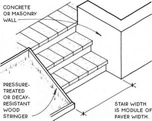
Dry-set concrete paver steps, like dry-set brick steps, are supported on a bed of compacted gravel on the ground and are laid dry without concrete or mortar. Because of their size, large pavers like the ones shown here are more stable than bricks. For this reason, paver stairs may be constructed without containment at the riser; some paver stairs are even constructed without

containment at the sides.

16-IN.

CONCRETE

PAVER

paver projects over riser about 1 IN.

-cl

Щщт

compacted rock base or self-compacting pea gravel

Most paver stairs are contained at the sides with walls or stringers, as shown below.

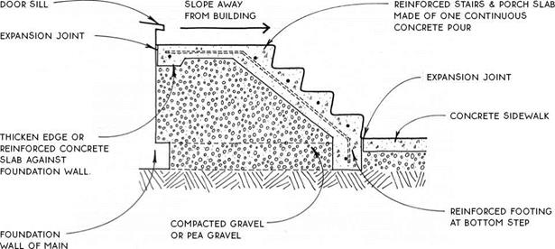
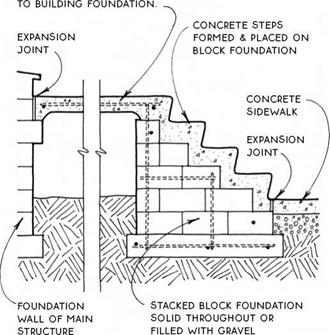
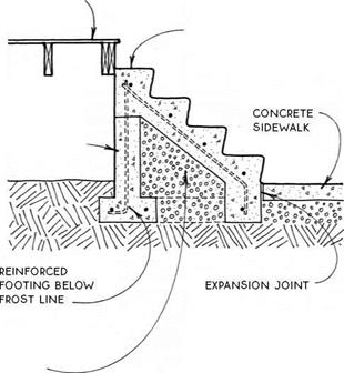
Concrete steps are durable and can be reasonably inexpensive, especially if they are built along with other concrete work. They should be adequately supported on a foundation and should be reinforced. Handrails or handrail supports may be cast into the steps or into the walks, porches, or terraces adjacent to them. The steps may be covered with a masonry or other veneer.

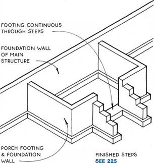
The main problem with concrete steps is that they are difficult to repair if anything should go wrong with them. The usual problem is settling due to the extreme weight of the steps themselves and to the fact that they are often constructed on fill. The safest way to avoid settling is to provide for the porch and steps a footing that is below the frost line, with a foundation wall above. This footing and foundation wall system may be an integral part of the foundation of the main structure (see the detail below), or it may be independent of the main structure with an expansion joint adjacent to the main structure that will allow the porch to move slightly without cracking (see 225A & B). Alternatively, concrete steps may be built independent of the main structure and adjacent to a wood porch (see 225C). All methods are expensive but will avoid costly maintenance in the long run.

For areas where building on backfill cannot be avoided, a wood porch with a lightweight wood stair that can be easily releveled is the most practical (see 222).

DRY-SET EXTERIOR STEPS

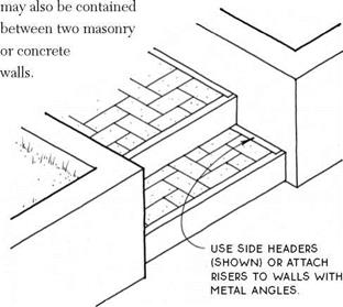
DRY-SET EXTERIOR STEPSПодпись:Paver stairs may also be contained at all edges like brick stairs with 2x risers and side headers (see 223).

DRY-SET EXTERIOR STEPS

Concrete Pavers

NOTE

ELEMENTS OF THE DETAiLS ON THiS PAGE MAY BE COMBiNED iN VARiOUS WAYS TO MEET THE NEEDS OF SPECiFiC SiTUATiONS.

DRY-SET EXTERIOR STEPS

structure

ДЛ CONCRETE STEPS ON GRAVEL

-__ ‘ At Concrete Porch

REINFORcED concrete pORcH spans from step FOuNDATION


wood porch SEE 52-60


REiNFORcED concrete steps


STEM Wall

including

SiDES IF

required


NOTE

coordinate WOOD porch SKIRT WITH EDGE OF cONcRETE STAIR.


compacted gravel OR pea gravel


DRY-SET EXTERIOR STEPSDRY-SET EXTERIOR STEPS

Подпись: CONCRETE STEPS ON BLOCK At Concrete Porch CONCRETE STEPS AT WOOD PORCH

On Block or Gravel

legend


CONTINUOUS STRUCTURAL FRAMING MEMBER


CONCRETE


DRY-SET EXTERIOR STEPS

BLOCKING (NOT CONTINUOUS)


GRAVEL FILL


oo^o. Я’О


I


WOOD FINISH MATERIAL


UNDISTURBED SOIL


і


PLYWOOD OR OTHER STRUCTURAL PANEL


SAND FILL


STUCCO OR GYPSUM WALL BOARD (G. W.B.)


RIGID INSULATION


MATERIAL BURIED IN ANOTHER MATERIAL.

E. G., REBAR IN CONCRETE


ВАТТ INSULATION


MASONRY-BRICK OR CONCRETE BLOCK


FUTURE

CONSTRUCTION


DRY-SET EXTERIOR STEPSDRY-SET EXTERIOR STEPSDRY-SET EXTERIOR STEPSDRY-SET EXTERIOR STEPSDRY-SET EXTERIOR STEPSDRY-SET EXTERIOR STEPSDRY-SET EXTERIOR STEPS

FREESPANNING-STAIR BALUSTRADE

STAIRS

Handrails


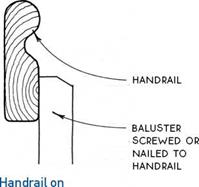
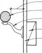
Handrails provide stability and security for the young, the old, the blind, and the infirm. In addition, handrails are a safety feature for anyone who uses a stairway—one of the most likely and dangerous places for people to trip and fall.

In terms of safety, the most important design feature of a handrail is its ability to be grasped, especially in an emergency. The іУз-іп. to 2-in. round rail is the most effective in this regard, as it allows the thumb and fin­gers to curl around and under the rail. Other shapes are allowable by code, but are less graspable.

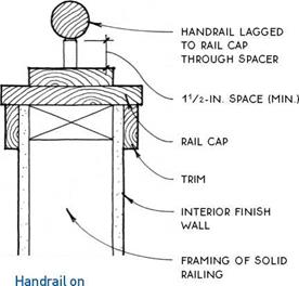
The height of the handrail is usually specified by code. Most codes fall within the range of 29 in. to 36 in. above the nosing of the stairs. If the handrail is against a wall, a 1 Уз-in. space is required between the handrail and the wall.

The tops and bottoms of handrails should be designed so as to avoid snagging clothing. For this reason, many codes require returning handrails to the wall at both top and bottom.


HANDRAiL LAGGED TO BLOCKiNG THROUGH SPACER

1V2-IN. SPACER (MiN.) BLOCKiNG

interior finish wall


Handrail Screwed to Wall through Spacer


IV2-IN. SPACE (MIN.)

HANDRAIL

METAL BRACKET

BLOCKING

INTERIOR FINISH WALL


FREESPANNING-STAIR BALUSTRADE

Open Balustrade


Handrail Attached to Wall with Metal Brackets


FREESPANNING-STAIR BALUSTRADE

Closed Balustrade


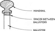
Traditional Handrail on Open Balustrade


^ HANDRAILS


FREESPANNING-STAIR BALUSTRADEFREESPANNING-STAIR BALUSTRADEFREESPANNING-STAIR BALUSTRADE

Exterior stairs made of wood should be built of weather-resistant species such as cedar or redwood or of pressure-treated lumber. Simple connections that minimize joints between boards are less likely to retain moisture. Where joints must occur, it is best to mini­mize the area of contact between pieces so that mois­ture will drain and the lumber can breathe.

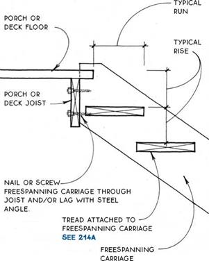
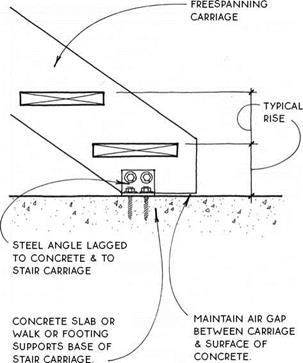
FREESPANNING-STAIR BALUSTRADEMost exterior wood stairs are freespanning. For long runs of stairs, the continuous unnotched carriage is usually required for strength (see 222B & D). Short runs of freespanning stairs may be strong enough with a notched carriage (see 222C). The notched carriage is, of course, also suitable for wood stairs built between two parallel concrete or masonry walls.

FREESPANNING-STAIR BALUSTRADE

Подпись: EXTERIOR WOOD STAIRS Introduction Подпись: EXTERIOR WOOD STAIRS Unnotched Carriage/Wood Porch

Open risers are often employed in exterior wood stairs, but solid risers, common on traditional porches, are useful to stiffen the treads. For wood porches, and decks, see 52-60.

FREESPANNING-STAIR BALUSTRADE

FREESPANNING-STAIR BALUSTRADEПодпись:Подпись: 2X8 RISER ALLOWS 7V2-IN. RISE.Подпись:FREESPANNING-STAIR BALUSTRADERiM JOiST OF PORCH

HEADER JOiST AT TOP OF STAiR CARRiAGE 2 X 12 NOTCHED CARRiAGE ALLOws

adequate structure only for short and medium freespanning stair runs.

FREESPANNING-STAIR BALUSTRADE

EXTERIOR WOOD STAIRS

Notched Carriage/Wood Porch

EXTERIOR WOOD STAIRS

Freespanning Carriage at Ground

FREESPANNING-STAIR BALUSTRADE

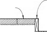
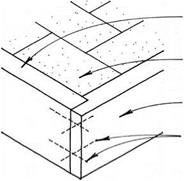
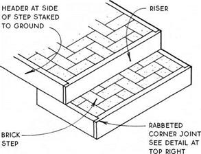
The rabbeted riser/side-header joint is nailed from


two directions to lock the joint together.


HEADER AT SIDE

of step


BRiCK

step


BRiCK (OR CONCRETE PAGERS)


2X PRESSURE-TREATED OR DECAy-RESiSTANT HEADER RiPPED TO RiSER HEiGHT & ATTACHED AT Ends To walls or HEADER


RiSER


nail joint through

RiSER & SIDE HEADER


о’о ° Ь ЧчЯ; О ° 0 °0°n°


2o« oo oo" o°o 0°

0 G О о О о о000 q

°°Ъ °о° Оо£%0а<>0 об


The sides of the brick steps

FREESPANNING-STAIR BALUSTRADE


FREESPANNING-STAIR BALUSTRADE

compacted rock base or self-compacting pea gravel


The sides of the steps may be contained with 2x headers the same height as the riser, as shown below. These side headers may be staked to the ground so that they contain the step at the sides on their own.


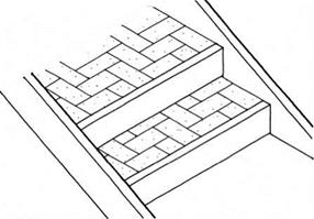
A third alternative is to contain the sides of the steps with decay-resistant stringers at the slope of the steps. The risers may be attached directly to the stringers.


. A STAIR LANDING

Подпись: NEWEL POSTNEWEL POST

Surface Anchored

. A STAIR LANDING
. A STAIR LANDING

2 Alternatives

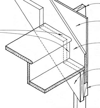
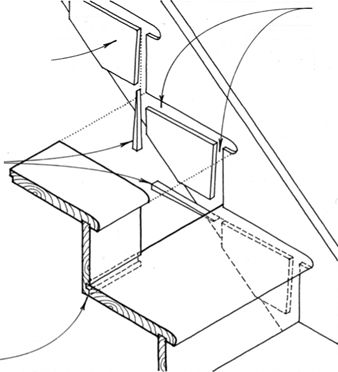
The advantage of the skirt over the housed stringer (see 217B) is the ease of construction. A disadvantage is the potential for minor opening of butt joints at the ends of treads and risers due to minor movement of the structure. A more involved hybrid strategy that limits this disadvantage is to install the risers first from wall to wall, cut out the stringers to fit to the risers, and finally install the treads tightly between the stringers.

Подпись: FiNiSH TREADS & RiSERS BUTT AGAiNST THE SKIRT & ARE GLUED & NAILED TO CARRIAGE ON WHiCH THEY ARE SUPPORTED. FOR TREAD & RISER SECTIONS, SEE 216. - Подпись: STUD OF SUPPORTING WALL Подпись:Подпись: FiNiSH STRINGER FITS BEHIND cARRiAGE & IS APPLIED DIRECTLY To FiNiSH WALL. Подпись: CARRIAGE NAILED TO SPACERПодпись: SPACER NAILED TO STUDS. A STAIR LANDINGПодпись:Подпись:Подпись:Подпись:. A STAIR LANDING

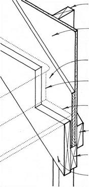
Подпись: HOUSED STRINGER AT FINISH WALL Подпись: The housed stringer is a more refined and complicated way than the skirt (see 217A) to provide a finish stringer at the side of a continuously supported stairway. The advantage of the housed stringer is that joints between treads, risers, and finish stringer will not open up with shrinkage or other minor movement of the structure. Disadvantages include the extra labor to build the housed stringer and the fact that it does not provide the framing for a temporary construction stair. Good- quality prefabricated stairs (see 213C) are also made with housed stringers.

дЬ FINISH STRINGER (SKIRT) AT FINISH WALL

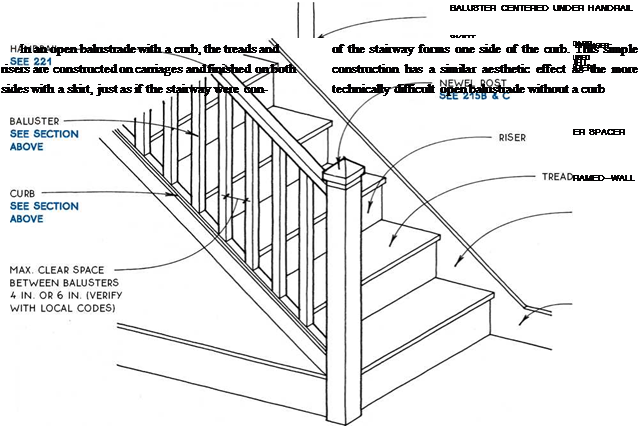
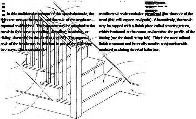
Подпись: (see 219).structed between two walls. The skirt on the open side

. A STAIR LANDING

. A STAIR LANDING

OPEN BALUSTRADE

With Curb

Подпись: Without Curb. A STAIR LANDING
дА OPEN BALUSTRADE

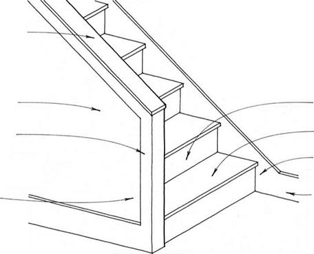
Подпись:Подпись:Подпись:Подпись:Подпись:Подпись:. A STAIR LANDINGПодпись:Подпись: FRAMING TO STIFFEN BASE AS FOR NEWEL POST SEE 215B& CThe closed balustrade is veiy economical to build because it involves the least finish work of any balus­trade system. The balustrade is framed like a standard wall (except that the base must be anchored like a newel post to resist lateral forces (see 215B). The stairway may be finished simply on both sides with finish stringers.

. A STAIR LANDING

Подпись: HANDRAIL SEE 221 BALUSTER Подпись:Подпись: CARRIAGEПодпись: TREAD SEE 214AПодпись: BASEBOARD IF STAIRWAY IS ADJACENT To A wALL . A STAIR LANDINGдЛ CLOSED BALUSTRADE

structural

CARRIAGE

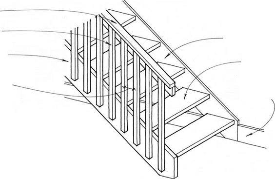
MAx. SpACE 4 IN. To 6 in. (verify with local code)

The freespanning stair usually has a structural carriage to which the balusters may be attached. This arrangement allows the balusters themselves to be the structural support for the handrail. A newel post, if used, would typically be attached to the side of the structural carriage in the same fashion as the balusters.

TOP OF CARRIAGE/FLOOR

Hangerboard Supports Top of Stair

stud of

SuppORTiNG wALL


GypsuM wallboard

OR OTHER FiNiSH

wall


1x FiNiSH STRiNGER


FiNiSH RiSER TRiMS TO STRiNGER.


FiNiSH TREAD TRiMS TO STRiNGER.


BLOcKING BEHiND wALL FiNiSH


2x spacer nailed to studs

carriage nailed to spacer


TOP OF CARRIAGE/FLOORTOP OF CARRIAGE/FLOOR

Подпись: TOP OF CARRIAGE/FLOOR Wall Supports Top of Stair CARRIAGE FRAMING/SIDE WALL

Continuously Supported Stair

HEADER AT END OF STAIR

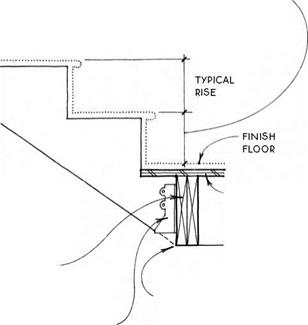
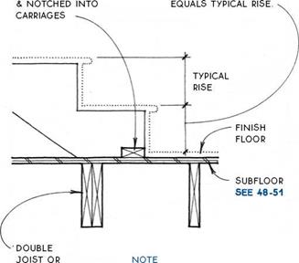
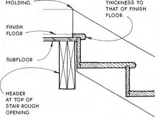
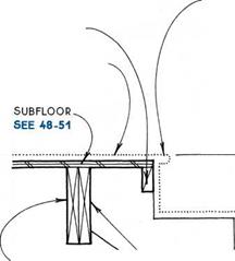
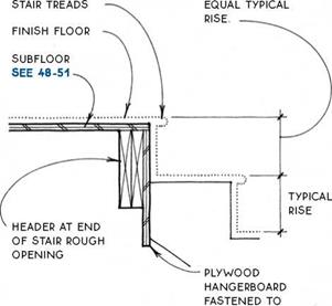
Подпись:Подпись: RISE FROM FINISH FLOOR TO FIRST TREAD EQuALS TYpicAL RISE.Подпись: SuBFLOOR SEE 48-51Подпись: LOCATE FLOOR HEADER TO INTERSECT WITH BOTTOM OF CARRIAGES.TOP OF CARRIAGE/FLOORПодпись: 2X THRUST BLOCK NAILED TO SUBFLOORПодпись: RiSE FROM FINISH FLOOR TO FIRST TREADTOP OF CARRIAGE/FLOORПодпись: BLOCKING TO SUPPORT STAIR Подпись: BLOCK BETWEEN FLOOR JOISTS IF BASE OF CARRIAGE DOES NOT FALL ON Tip OF JOIST.rough

OpENING FOR

multiple

FLIGHTS OF STAIRS

JOIST HANGER

TOP OF CARRIAGE/FLOOR TOP OF CARRIAGE/FLOOR

supports central carriage

TOP OF CARRIAGE/FLOORПодпись: INTERIOR FINISH WALLTOP OF CARRIAGE/FLOORHOuSED STRINGER OF pREFABRicATED STAIR

5/8-IN. TO 1-IN.

shim accommodates thickness OF FINISH WALL

ATTAcH STRINGER WITH 16D NAILS THROuGH SHIMS INTO FRAMING

WALL FRAMING

Подпись: Section at Side WallSection at Top of Stair

PREFABRICATED STAIR

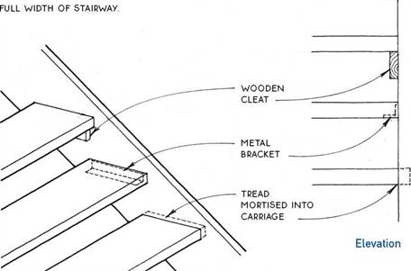
Подпись: ATTACHMENT OF TREADS TO CARRiAGE MAY BE WiTH:

WOODEN cLEATS

Подпись:TOP OF CARRIAGE/FLOORscrewed TO Structural cARRIAGE;

OR

metal bracket let into

END Of TREAD SO THAT

bracket is concealed

FROM ABOvE (AND DOES NOT pROJEcT BELOW);

OR

MORTISED TREAD, WHicH

provides concealed connection FOR AppEARANcE; ScREW TREADS THROuGH

carriage or glue &

TOENAIL FROM underside INTO carriage.

Finish landings must be at least as deep as the stairway is wide (automatic in the case of an L-shaped stair). Set the landing height so that the finish-floor level corre­sponds to the rise of the stair.

Подпись:Подпись: / .«■*;.< /Подпись: FRAME LANDiNG AS A FLOOR SEE 32 —Подпись: EXTEND LANDING UNDER CARRIAGE OF UPPER FLIGHT OF STAIRS.Подпись: ATTACH CARRIAGE OF LOWER FLIGHT OF STAIRS TO SIDE OF LANDiNG. SEE 212A, В & cTOP OF CARRIAGE/FLOORSUPPORT LANDiNG ON STUD WALLS.

Site-built versus prefabricated stairs

Most stairs are site-built because it is economical and because the process provides a temporary stair for construction. But in some cases, stairs prefabricated in a shop are more practical. Prefabricated stairs (see 213C), whether simple or complex, can be made more solidly and precisely than site-built stairs because they are made in the controlled environment of a shop.

additional decisions

There are several other design decisions to make regarding both interior and exterior stairs. The primary decisions concern whether the risers are open (see 214A) or closed (see 216) and the design of the balus­trade (see 218-220) and the handrail (see 221).

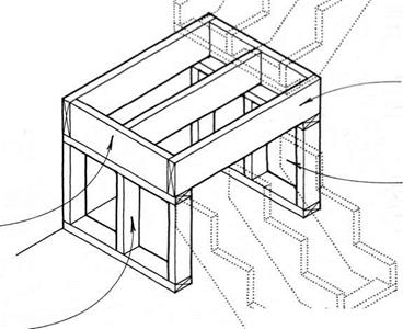
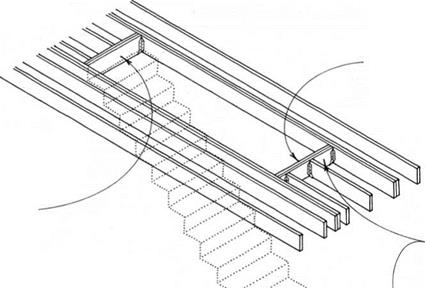
Подпись: FRAMING OF ROUGH OPENING IN FLOOR SEE 38BПодпись:Подпись: THIS HEADER CAN SLOPE IN TIGHT SITUATIONS.Site-built versus prefabricated stairsDOUBLE 2X HEADER AT TOP OF STAiR (DASHED); POSiTiON DETERMiNED ВУ METHOD OF CARRiAGE CONNECTiON SEE 212

NOTE

wiDTH Of ROuGH OpENiNG DEpENDs ON wiDTH OF sTAiR; FOR sTAiR wiDTH, sEE 207. cODE REQuIREMENTs FOR wiDTH ARE FOR

clear openings, so allow for thickness of wall finish when dimensioning a rough opening.

д STAIR ROUGH OPENING

HEADER AT END OF STAiR ROuGH opening SEE 211A & 212

Top OF carriage/

FLOOR

SEE 212A, В & c

FOR FREESpANNING STAiR FRAMING,

SEE 213A & B.

FOR cARRiAGE FRAMING

at open balustrade, SEE 219 carriage framing/ side wall SEE 212D

NOTE

Top OF BASE OF STAiR MAy TERMINATE AT A FLOOR LEvEL OR A LANDING. THE STAiR FRAMING cAN BE THE SAME IN EITHER cASE.

CARRIAGE FRAMING

Continuously Supported Stair

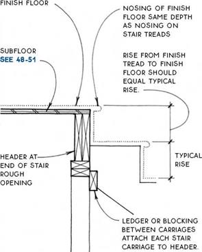
NOSiNG OF FiNiSH FLOOR SAME DEpTH AS NOSiNG ON STAiR TREADS

RiSE From FiNiSH TREAD TO FiNiSH FLOOR SHOuLD EQuAL TypicAL RiSE


BLOCKiNG BETWEEN CARRiAGES SUPPORTS SUBFLOOR.


NOSiNG OF FiNiSH FLOOR SAME DEpTH AS NOSiNG ON


RiSE FROM FiNiSH TREAD TO FiNiSH FLOOR SHOuLD


FiNiSH FLOOR


TypicAL

RiSE


HEADER AT END OF STAiR ROUGH OPENiNG


NOTE

SiDE cARRiERS ARE SuppORTED cONTiNuOuSLy ON wALL FRAMiNG.

SEE 212D


LEDGER, BLOCKiNG, JOiST HANGERS ATTAcH EAcH STAiR cARRiAGE TO HEADER; SEE 211B For LEDGER.


cARRiAGES &

TO HEADER (AND/OR wALL)


Site-built versus prefabricated stairsSite-built versus prefabricated stairsSite-built versus prefabricated stairsSite-built versus prefabricated stairs

Site-built versus prefabricated stairs

TOP OF CARRIAGE/FLOOR

Floor Supports Top of Stair

Interior and exterior stairs

The basic structure of the stair depends primarily on whether the stairway is to be located inside or outside and whether it is to be protected from the weather or not. The wood-stair details discussed in this chapter can be employed for either interior or exterior stair­ways, although the location will suggest basic detailing differences due to the fact that one is protected from the weather and the other isn’t.

Interior stairs—Interior stairs are usually more refined than exterior stairs. Interior stairways may be the showcase of a building and so are often located near the entry and used as a major circulation route. They may also provide the opportunity to connect more than one floor with natural light.

Exterior stairs—Exterior stairs (see 222) have the same minimum proportional requirements as interior stairs, but they are generally built less steep. The treads need to be deeper and risers shallower outdoors to make the stairs safer when wet or covered with snow or ice. Materials on exterior stairs must also be chosen with the weather in mind. Weather-resistant materials such as concrete, masonry, and metal are sound choices for stairs exposed to the elements. Heavy timber or pressure-treated wood is often chosen for a wood stair out of doors. Special attention should be paid to non­skid surfaces for treads exposed to the weather.

Some exterior stairs are supported directly on the ground, in which case they are usually called steps (see 223-225). Ground-supported steps follow the contours of sloping sites to provide easy access to porches or entrances or as connections between terraces and other landscape elements.

Structure

Stairs may be classified into two basic structural types: continuously supported and freespanning.

Continuously supported stairs—Continuously supported stairs are commonly used as interior stairs. Both sides of the stairway are supported by wall framing, so calculations of spanning capacities are not necessary. These stairs are site-built in some regions, but are predominantly prefabricated in others.

Structure

Continuously Supported Stair (Shown with Closed Risers)

Freespanning stairs—Freespanning stairs have the structural capacity to span from the bottom stair to the top stair without intermediate support. The freespan­ning stair is commonly used as an exterior stair between floors or landing levels or in conjunction with porches and decks. It is often also seen as an access stair to basements and attics. The strength of a freespanning stair is usually in the carriages (stringers) that support the treads, although the handrail may also contribute to the strength of the stair. Freespanning stairs, like continuously supported stairs, may be site-built or pre­fabricated. Some freespanning stairs have only a single central support.

Prefabricated Custom Stair (May be Freespanning or Continuously Supported)

Stair configuration

The shape or configuration of a stairway is determined primarily by the circulation patterns of a building and by available space. Virtually any configuration of stairway may be constructed using the standard details of this chapter by merely breaking the stairway into smaller pieces and reassembling them. Several typical configurations that are worthy of note are shown in the drawings that follow; for clarity, these drawings do not show railings.

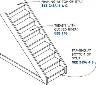
Straight-run stair—The straight-run stair is the most economical standard stairway from the stand­point of efficiency of floor space taken up by the stairway itself. The straight-run stair works best in two-story buildings.

Stair configuration

The bottom and top steps are separated horizontally from each other by the entire length of the stairway, so that a multistory building with stacked stairways requires circulation space on each floor to get from the top step of one flight to the bottom step of the next.

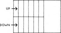
U-Shaped Stair— The U-shaped stair, also called a switchback stair, has a landing about half a flight up, and the flights run in opposite directions. The area of the stairway is increased over a straight-run stair by the area of the landing (less one step), but the top step of one flight is adjacent to the bottom step of the next. This arrangement saves circulation space at each floor level and makes this stair more efficient overall for multistory buildings than the straight-run stair.

Stair configuration

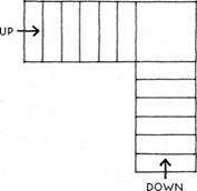
L-Shaped stair—The L-shaped stair is not so common as the straight or U-shaped stair because it lacks the simplicity of the straight-run stair and the efficiency of the U-shaped stair. It can, however, be useful in tight spots, as it takes up less floor space than a U-shaped stair and requires less length than a straight-run stair. The framing of the opening in the floor for this stairway can be atypical because of its L-shape. A framed wall under one side of the floor projecting into the L or a column under the floor at the bend in the L is the most common way to support this floor.

Stair configuration

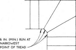
Winder stairs at the bend in the L (or at the bend in a U-shaped stair) are common, but for reasons of safety, should not be allowed to be less than 6 in. deep at the narrow end (verify with local codes).

Stair configuration

Spiral Stair – A spiral stair saves space. It is most appropriate for accessing mezzanines and lofts where furniture and other large items may actually be hoisted from floor to floor by means other than the stairway. Spiral stairs usually have special code requirements that are somewhat less restrictive than standard stairs. They are usually prefabricated, often of metal or wood kits. Their details are idiosyncratic and not included in this book.

Stair

Stair

S

tairs do not really support or protect a building in the same way as foundations, floors, walls, and roofs, but this book would be incomplete without them. Stairs are the vertical connectors of the parts of the building. Most buildings require a few steps just to enter the main floor, and stairs connect any internal levels. A well-designed and well-built stair­case can contribute immeasurably to the function and beauty of a building.

STAIR DIMENSIONS

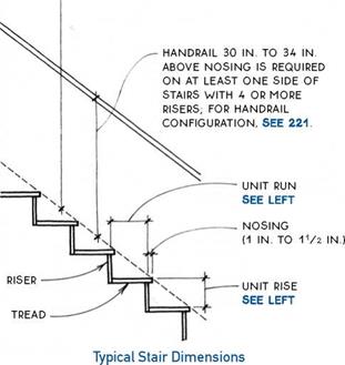
More than most other parts of a building, stairs need to be proportioned to the human body for safety. The height (rise) and depth (run) of the individual step must be in a comfortable relationship for the average person and must be manageable for people who are infirm or disabled. Building codes prescribe a range of dimen­sions for rise and run, a minimum width for stairways, the location of handrails, and minimum head clear­ance over stairs. The numbers vaiy depending on the location of the stair, the building type, and the specific code; the typical requirements are outlined as follows:

Rise and ШП— Rise and run of stairs are governed by building codes, which may vaiy. Minimum unit rise is typically 4 in. and maximum is 7 in., except for resi­dential stairs, which can have a unit rise of 73/4 in. For residential stairs, however, a comfortable rise is about 7 in. Minimum unit run is 11 in., except for residential stairs, which can have 10-in. treads.

Generally, deeper treads have shallower risers.

Flere are two useful rules of thumb for the rise/run relationship:

rise + run = 17 in. to 18 in.

run + twice the rise = 24 in. to 26 in.

Both for safety and for code compliance, it is impor­tant to make each riser of a stair the same height. Most codes allow only 3/8-in. variance between the tallest and shortest riser in a flight of stairs. The maximum total rise between floors or landings is typically 12 ft. Landings must be as deep as the width of the stairway but need not exceed 44 in. if the stair has a straight run.

Stair width— The width of stairways is also defined by building codes. Minimum width is usually 36 in. for residential stairs. Minimum widths are measured inside finished stair­wells, so rough openings must allow for finished wall surfaces.

HEADROOM is MEASURED VERTiCALLY FROM AN iMAGiNARY LiNE CONNECTiNG THE NOSiNG OF ALL TREADS;

MiNiMUM HEADROOM REQUiRED BY CODE iS TYPiCALLY 6 FT. 8 iN.

ALTHOUGH 7 Ft. is MORE Comfortable.

Stair

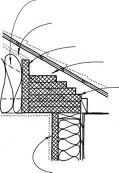
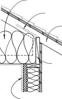
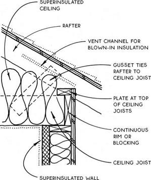
SUPERINSULATED CEILINGS

SUPERiNSULATED

CEiLiNG


SUPERiNSULATED

CEiLiNG


VENT cHANNEL FOR BLOwN-IN iNSULATiON


VENT CHANNEL FOR BLOWN-iN iNSULATiON


raised-heel

TRUSS SEE 198


RiGiD iNSULATiON BAFFLE


STANDARD TRUSS OR RAFTER WiTH TiE


RiGiD

iNSULATiON WiTH R-VALUE EQUAL TO CENTRAL pORTiON OF MAiN cEiLiNG


blocking between TRUSSES TO prevent ROTATION


SUpERiNSULATED wALL


SUpERiNSULATED wALL


SUPERINSULATED CEILINGSSUPERINSULATED CEILINGS

SUPERINSULATED CEILING

Rigid Insulation

SUPERINSULATED CEILING

Raised-Heel Truss
SUPERINSULATED CEILINGSSUPERINSULATED CEILINGS

SUPERINSULATED CEILING

Dropped Ceiling

SUPERINSULATED CEILING

Raised Plate

GABLE VENTS SEE 201


VENTiiNG AN ABUTTiNG ROOF SEE 150D. 204


SUPERINSULATED CEILINGS

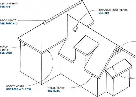
Roofs and attics must be vented to prevent heat buildup in summer and to help minimize condensa­tion in winter. (Condensation is reduced primarily by the installation of a vapor barrier, see 197.) In addition, winter ventilation is necessary in cold climates to pre­vent escaping heat from melting snow that can refreeze and cause structural or moisture damage.

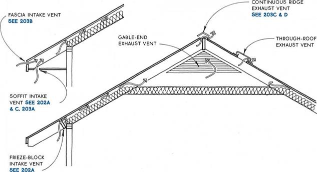
The best way to ventilate a roof or attic is with both low (intake) and high (exhaust) vents, which together create convection currents. Codes recognize this by allowing the ventilation area to be cut in half if vents are placed both high and low. Most codes allow the net free-ventilating area to be reduced from Уібо to У300 of the area vented if half of the vents are 3 ft. above the eave line, with the other half located at the eave line.

Passive ventilation using convection will suffice for almost every winter venting need, but active ventila­tion is preferred in some areas for the warm season. Electric-powered fan ventilators improve summer cooling by moving more air through the attic space
to remove the heat that has entered the attic space through the roof. The use of fans should be carefully coordinated with the intake and exhaust venting dis­cussed in this section so that the flow of air through the attic is maximized.

Some roofing materials (e. g., shakes, shingles, and tile) are self-venting if applied over open sheathing. These roof assemblies can provide significant ventila­tion directly through voids in the roof itself. Check with local building officials to verify the acceptance of this type of ventilation.

A special roof, called a cold roof (see 204A), is designed to ventilate vaulted ceilings in extremely cold climates. The cold roof prevents the formation of ice dams—formed when snow thawed by escaping heat refreezes at the eave. When an ice dam forms, thawed snow can pond behind it and eventually find its way into the structure. The cold roof prevents ice dams by using ventilation to isolate the snow from the heated space.

A R00F & ATTIC VENTING
SUPERINSULATED CEILINGS

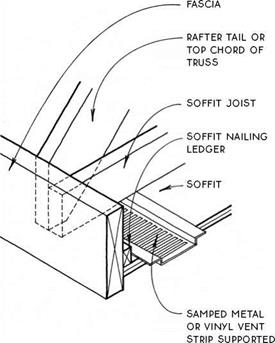
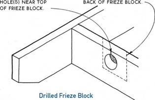
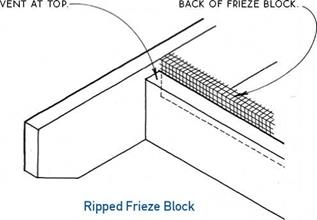
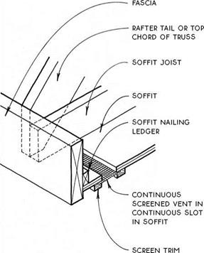
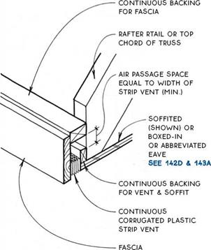
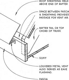
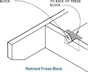
Intake vents—Intake vents are commonly located either in a frieze block or in a soffit or fascia. They are usually screened to keep out birds and insects. The screening itself impedes the flow of air, so the vent area should be increased to allow for the screen (by a factor of 1.25 for V8-in. mesh screen, 2.0 for //L6-in. screen). The net venting area of all intake vents together should equal about half of the total area of vents.

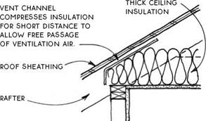
Vent channels may be applied to the underside of the roof sheathing in locations where the free flow of air from intake vents may be restricted by insulation. The vent channels provide an air space by holding the insulation away from the sheathing. These channels should be used only for short distances, such as at the edge of an insulated ceiling. For alternative solutions to this problem, see 198 & 199.

SUPERINSULATED CEILINGS

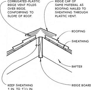
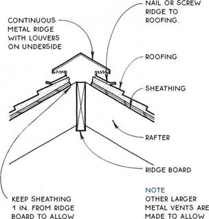
Exhaust vents—If appropriately sized and balanced with intake vents, exhaust vents should remove excess moisture in winter. There are three types of exhaust vents: the continuous ridge vent, the gable-end vent, and the through-roof exhaust vent.

The continuous ridge vent is best for preventing summer heat buildup because it is located highest on the roof and theoretically draws ventilation air evenly across the entire underside of the roof surface. Ridge vents can be awkward looking, but they can also be fairly unobtrusive if detailed carefully (see 203C &

D). (Another type of ridge vent, the cupola, is also an effective ventilator, but is difficult to waterproof against wind-driven rain.)

The gable-end vent is a reasonably economical exhaust vent. Gable-end vents should be located across the attic space from one another. They are readily avail­able in metal, vinyl, or wood, and in round, rectangular or triangular shapes. Because the shape of gable-end vents can be visually dominant, they may be empha­sized as a design feature of the building.

The through-roof exhaust vent is available as the “cake pan" type illustrated above or the larger rotating turbine type, available in many sizes. Through-roof vents are usually shingled into the roof and are useful for areas difficult to vent with a continuous ridge vent or a gable-end vent.

NOTCH TOP OF FRiEZE FOLD SCREEN & STAPLE
SUPERINSULATED CEILINGS


RiP FRiEZE BLOCK TO FOLD SCREEN, PRESS UP

ALLOW CONTiNUOUS TO SHEATHiNG & STAPLE TO


SUPERINSULATED CEILINGS

В


SUPERINSULATED CEILINGS

by SOFFiT


BORE ROuND VENT Staple SCREEN TO

SUPERINSULATED CEILINGS


FRIEZE-BLOCK INTAKE VENTS

Three Types


SOFFIT INTAKE VENT

Stamped


SUPERINSULATED CEILINGSSUPERINSULATED CEILINGSSUPERINSULATED CEILINGS

SUPERINSULATED CEILINGS

SUPERINSULATED CEILINGSSUPERINSULATED CEILINGS

SUPERINSULATED CEILINGS

SOFFIT INAKE VENT

Corrugated Strip

FASCIA INTAKE VENT

Starter

SUPERINSULATED CEILINGS

FROM RIDGE BOARD TO ALLOW FREE AIR pASSAGE.


SUPERINSULATED CEILINGS

FREE AIR PASSAGE. SHiNGLiNG-OVER

OF VENT FOR APPEARANCE.


RIDGE EXHAUST VENT

RIDGE EXHAUST VENT

AIR CHANNEL CONTiNUOUS TO VENT(S)

AT TOP OF ROOF. VENTS MUST HAVE AREA EQUAL TO SOFFIT VENTS AND NOT BE SUSCEPTIBLE TO CLOGGING ВУ SNOW.


ROOFING


2×4 sleepers aligned with

RAFTERS pROViDE

continuous AIR cHANNEL FOR VENTILATION.


31/2-in. continuous ScREENED SOFFIT VENT


CONTINUOUS SHEATHING COVERED WITH 30-LB. FELT


NOTE

INSULATION

can be batts

W/VENTED AIR Space OR RIGID INSULATION THAT FILLS cAVITy.


INSULATION BETWEEN RAFTERS WITH VAPOR BARRIER ON WARM SIDE BELOW


SUPERINSULATED CEILINGSSUPERINSULATED CEILINGS

The cold roof is a way to protect vaulted ceilings in cold climates from the formation of ice dams. A cold roof is a double-layer roof with the upper layer vented and the lower layer insulated. The vented layer promotes continuous unrestricted air flow from eave to ridge across the entire area of the roof. This flow of cold air removes any heat that escapes through the insulated layer below. The entire outer roof surface is thus maintained at the temperature of the ambient air, thereby preventing the freeze-thaw cycle caused by heat escaping through the insulation of conventional roofs.

The typical cold roof is built with sleepers aligned over rafters and with continuous eave vents and comple­mentary ridge or gable vents. A 3f/2-in. air space has been found to provide adequate ventilation, but a іУг-т. air space does not. The sleepers must be held away from obstructions such as skylights, vents, hips, and valleys to allow air to flow continuously around them.

A modified cold roof with extra-deep rafters to pro­vide deeper than normal ventilation space but without the double-layer ventilation system can also work.

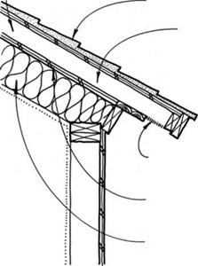
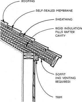
The warm roof also protects vaulted ceilings in cold climates from the formation of ice dams. Instead of isolating the snow from the insulation like a cold roof however, the warm roof prevents escaping heat from melting the snow by increasing insulation thickness. When the ceiling R-value is sufficient (approximately R-50 is recommended), the temperature on the surface of the roof can be maintained at the temperature of the snow. The snow will therefore not melt while the ambient temperature remains below freezing.

By using rigid insulation, the warm roof eliminates the ventilation space because there are no voids within which condensation can form, so there is no need to ventilate between the insulation and the roof surface. With snow effectively adjacent to the insulation, the insulative value of the snow itself will contribute to the insulation of the building. In this respect, the warm roof is superior to the cold roof because the cold roof exposes the outer surface of the insulation to ambient air (which can be significantly colder than snow).

When compared to the cold roof, the warm roof is less complicated to build and will insulate better. It is made with expensive materials, however, so may have a higher first cost—especially for owner-builders.

Подпись: WARM ROOFA cold roqf

Flat roofs, like sloped roofs, require ventilation to prevent heat buildup and to minimize condensation. The principles of ventilation are the same for flat roofs as for sloped roofs, but flat roofs have some particular ventilation requirements due to their shape. On a flat roof, a low intake vent can rarely be balanced by a high exhaust vent (3 ft. min. above the intake vent). The
net free-ventilating area therefore cannot usually be reduced from кІ50 of the area of the roof.

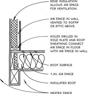
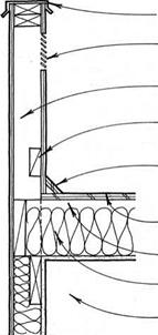
Flat-roof ventilators are commonly of the continuous strip type, located at a soffit, or a series of small vents scattered across the roof. Parapet walls can also provide effective ventilation for flat roofs (see 205B).

ROOF VENT ABOVE VENT iN PARAPET WALL

SUPERINSULATED CEILINGS


FLAT-ROOF VENTING

SUPERINSULATED CEILINGS

NOTE

seal carefully between framing members

AND RIGID iNSuLATiON TO PREVENT AiR INFILTRATION.


CAP FLASHiNG

WALL VENTS AS REQUiRED

PARAPET WALL

BLOCKING ALLOWS SPACE FOR AiR PASSAGE

cant strip

ROOF SuRFAcE

1-IN. AiR SPAcE required

Insulated ROOF

heated space


NOTE

IT MAY Be uSEFuL TO Be Able TO VENT AN iNSuLATED ROOF (OR DEOO THROuGH A PARAPET wALL IN ORDER TO GET cROSS VENTILATION.


SUPERINSULATED CEILINGS

VENTED PARAPET WALL