Category Timber Framing for the Rest of Us Rob Roy

Installing Posts

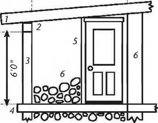
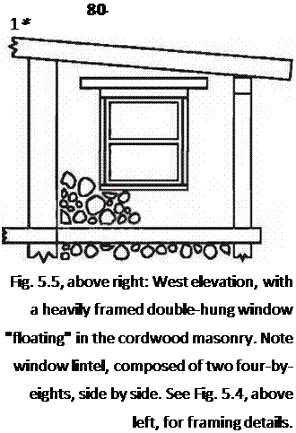
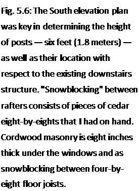
From the plan, we know that the posts should be six feet (1.8 meters) long. With the eight-by-ten girders on top of them, this gives six foot ten inches of clearance to the underside of the rafters at the lowest point. And it is seven foot eight inches to the ceiling, so there is a cozy, but not oppressive, feeling of space in the room. The rafter clearance is a few inches greater near the house.

Jaki and I were joined by family and interested friends for the remainder of the framing and roofing projects, including sons Darin and Rohan, Anna Milburn-Lauer, Bruce Kilgore, Diane Lukaris, and Stephanie Bayan. Work became fun with this rotating crew, a huge advantage.

I cut eight-by-eights with a chainsaw. The saw needs to be well sharpened, which means that it must not only cut easy, but also true, without pulling one way The very best way to assure straight cutting is to use a new bar and new chain. The next best way is to use a chain which has been professionally sharpened with a machine for the purpose. In any case, don’t make your first cut on an important short post. If you mess it up, the post may be rendered useless. Practice your technique on a long eight-by-eight, and keep cutting two inches (5.1 centimeters) off it until you can do a good job with regularity. Finally, when you’ve got a good square right-angled cut, and your confidence is high, measure, mark and cut the other end to length.

Bruce Kilgore made a wonderful cordwood cutoff saw, for use in making very regular log-ends for his house. He loaned me the saw, and I used it to cut quite a few of the heavy timbers for our sunroom frame. An explanation of how to make this saw is shown at pages 74—77 of my previous book Cordwood Building: The State of the Art (see Bibliography). A saw like this affords great control options. The swing of the saw can be fine-tuned to give a vertical cut every time. If need be, a shingle can be installed as a shim against the backrest of the table, giving another opportunity for fine angle adjustments. See pages 124—125.

No matter what method of cutting you choose, the cut may need to be dressed a little if it is still not square. Check it again with the large framing square and mark any high bits on the cut with a pencil. A little extra wood can be removed easily with a small Stanley Sure-Form™ Scraper, which has a 2- by 21/2-inch (5.1- by 6.3- centimeter) rasp on one end, and a handle that is used to pull the rasp towards you. You can put a lot of pressure on the wood with this tool, and it can remove wood very quickly. Another tool I use for the same purpose is my 5"-diameter Makita 4000-rpm circular sander, with #36-grit sanding disks for heavy wood removal, and #80 grit for finer work. Hint: very often, removing a high spot at the center of the new cut will stop a post from wobbling. Let the post bear on the edges.

Frequent use of the square and pencil is imperative, and becomes habitual after a while. With hand-hewn beams, or a timber with considerable wane on the edge, you may want to run a straightedge along the surface of the beam, and use your square off of the straightedge.

Preparing the Girders

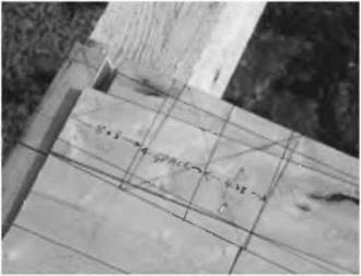
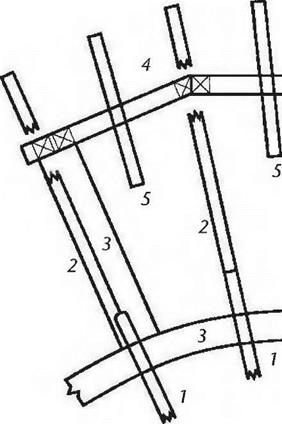
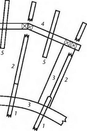
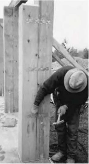
Once the floor was complete, I transposed the plans onto the deck with a black marker, at full scale. Now the position of every post could be seen clearly on the deck, and 1 could even show how the major south wall girders could abut with each other over the posts. See Fig. 5.22. I could check with the structure below to make sure that the line of thrust was transferred directly on compression to the post below, and not just missing them, as per Fig. 2.9 on page 24.

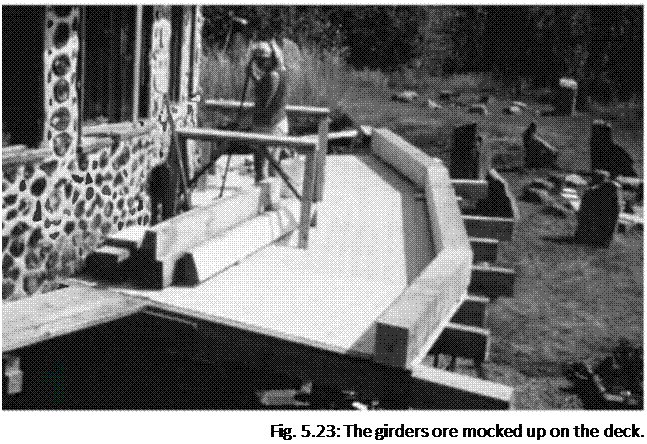
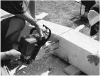
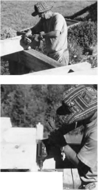
Before installing the posts, my family and I laid the girders out on the deck, supported on little blocks of wood. Then, the corresponding ends of the girders were cut at an angle so that they joined together fairly well. This was done by marking with a pencil and with judicious use of both an angle square and a regular framing square. Each piece was cut with a chainsaw. Now the girders were repositioned on the little blocks of wood, as in Fig. 5.23 and Fig. 5.24.

Подпись: Fig. 5.23: The girders ore mocked up on the deck. Подпись: Fig. 5.24: Passing a chainsaw down through the joint, maybe more than once, will eventually give a pretty good fit. Make sure the chain is sharp. If you shorten the central girder by a half-inch or so, thats okay. There is plenty of space on top of an eight-by-eight post. Let the shorter girders run long. They con be trimmed later.image131Unless one is a very skilled chainsaw carpenter, the chances are that the butt join between the two girders won’t be all that great. Good, possibly, but not great. You can make it great by butting the two girders together as closely as possible, and then passing the chainsaw down between them, as in Fig. 5.24. Helpers can lend their weight to the project, one on each girder. You may have to do this two or three times, butting the girders again after each cut. Pretty soon, you’ll have a great butt joint, and this joint will be ready for use when the girders are assembled permanently on top of the six – foot-high (1.8-meter-high) posts. It is just much easier to get these girders to match up well on the deck, than to do the work overhead. Be wary of chainsaw “kickback,” both while cutting and when the saw completes the cut.

Flooring (Decking)

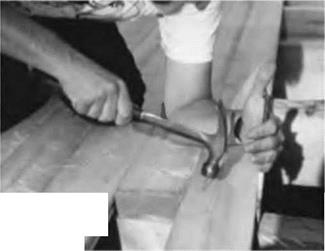
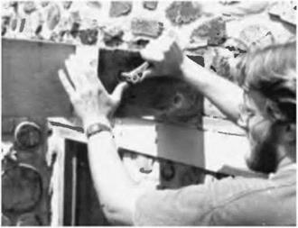
Подпись: Fig. 5.20: Doug draws the new board tight with a long spike, which has had its point driven a little ways into the joist. The spike is now a class 2 lever with tremendous mechanical advantage for drawing tongue-in- groove boards together. Start the nail first. image127We decided on two-by-six V-jointed tongue-and-groove spruce planking for our floor. The V-jointed side goes down, making an attractive ceiling as seen from the room below. We like it for its strength, appearance, and ease of installation. We also like the benefit of doing the floor and ceiling below in one operation, a real plus with the plank-and – beam system. Also, we wanted to maintain visual consistency with the original floor, because there would be a direct doorway opening from the dining room into the new sunroom.

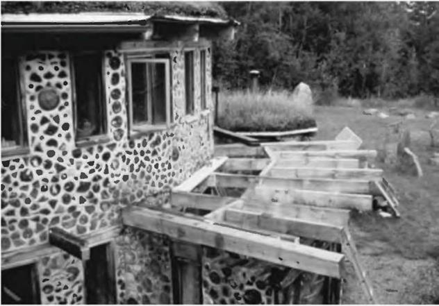
The toughest part of the planking was installing the first board, because it had to be scribed to fit a very rough-textured cordwood masonry wall, as can be seen in Fig. 5.19. Fortunately, the round house was slightly flattened at this point because of a six-foot wide sliding glass door unit below. Still, the first plank had to be scribed with a pencil and cut to fit up against the cordwood wall without huge gaps. I used chisels and a variety of saws to trim the edge that went up against the cordwood wall, the edge with the tongue on it. With new work, especially with conventional rectilinear construction, you will not have this sort of problem. Again, starting from scratch is easier.

Once the first plank was installed, the rest went quite easily. You could hire a machine for blind-nailing tongue-and-groove planking, but I have always used cup-headed nails to attach the planks. These nails can be driven slightly below the surface, so that the floor can be sanded prior to finishing. Use two nails at each place where the plank is supported by a joist, with the nails about an inch inward from both the end of the board and the edge. I insert the tongue of one board into the groove of the board already nailed, then use a ten-inch log cabin spike to draw the tongue absolutely tight into the groove, leaving no space between boards on the top surface. (Remember that the underside has that attractive V-joint, so the boards can only be laid with the non-jomted side up.) While holding the pressure with one hand, I drive the two nails in with the other. You might find it easier to start the nails before drawing the boards up snug. See Fig. 5.20.

With rectilinear buildings, you will want to design the building to maximize the use of the boards. The boards I was able to purchase came only in 12- and 16-
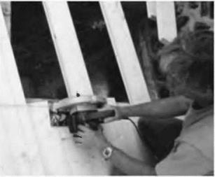
foot lengths. Our floor sections were trapezoidal in shape, so, with our ever- increasing planking span, scrap pieces would constantly get shorter. On subsequent sections, we used the scrap pieces in the reverse order in which they were created. We waited until the first large central section (or facet) was about half covered before cutting the ends. We snapped a chalk-line down the edge of the section, centered over the middle of the four-by-eight joist below. Then I set my circular saw’s blade so that it cut just a little bit deeper than the thickness of the planking, by about one-sixteenth inch (1.6 millimeters). Now I could cut a fair bit of the section at once, and get a nice straight line.

Подпись:image128Подпись: Fig. 5.22: All the important structural members are marked on the deck with a black marker.image129On subsequent facets, it is necessary to trim one end of the board to the proper angle in order to fit it up to the previous section. Use an adjustable angle square to measure and mark this angle. Again, let the extra length of the plank run long, so that all the ends can be trimmed at once. We did this upstairs on the roof planking, and the extra length of the board became the overhang, which was all trimmed at once by a single straight cut with the saw. See Fig. 5.21.

Doug Kerr and I tore out the old deck and joists, installed the new joists, and decked the whole area in just four days, not bad for renovation work. Thanks, Doug!

Installing Headers

A header is a short transverse wooden member used to provide support for an otherwise unsupported joist or rafter. An example is when a roof rafter needs to be cut to make way for a skylight; a header spans between the adjacent rafters to frame the skylight.

The floor joist system for our new room required headers for a different reason. As the radial floor joists get further from the center of the house, they also get

further apart from each other. This increases planking spans until we begin to experience a “springy” floor (deflection), an indication that plank­ing span is being stretched too far.

Подпись: Fig. 5.14: We mode ten of these little support pieces very quickly.image121Подпись: 3/8" nuts washersПодпись: 3/8"x 7" lag boltsПодпись: Fig. 5.15: The locations of the header, the header support piece, and the drill holes are all marked on the four-by-eight floor/ceiling joist. We actually used carriage bolts, but countersunk lag bolts could be used as well. Drawing by Doug Kerr. image122The simple solution would have been to run another radial floor joist hallway between the primary ones, cutting all planking spans in half. The problem was that there was an existing cordwood wall, which would have needed rebuilding to make room for one end of the new joists; a lot of work. Besides, planking spans were okay near the round house; they only started to get dicey a few feet away from the main building.

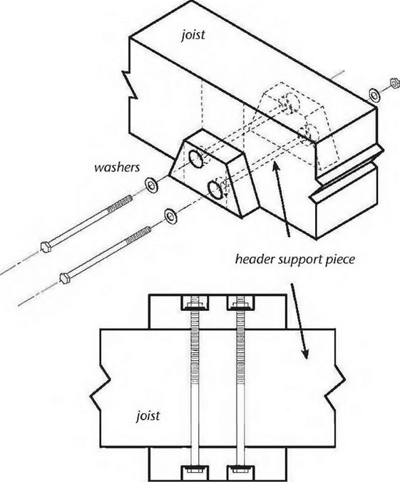
Four headers, as shown in Fig. 5.3, enabled us to support one end of a shorter secondary rafter. The existing girder would support its outermost end. There are two easy ways to fasten the headers: The first is to use metal joist hangers made for the purpose. But we didn’t want to see the galvanized hangers, and besides, our local supplier did not carry them for full-sized four – bys. The second is to use two strong lag bolts — say one-half-inch by eight inches — installed through the side of a joist and into the end grain of the header. Place them about two inches from the top and two inches from the bottom of the members, and centered on the width of the header. This was an attractive idea, but once one header

was installed, it would not be possible to install the next one in the same way — not if I wanted to maintain the symmetry of Fig. 5.3. I thought of offsetting each header by four inches, so that the lag screws could always be driven in, but this spoiled the symmetry and I would still have a problem getting lag screws into the headers where they meet the east and west cordwood walls.

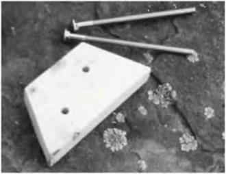
Once again, improvisation saved the day. I came up with a header support system that was attractive (it was made of wood), strong, and could be assembly – lined quite easily. I made ten little trapezoidal header support pieces from a standard two-by-four, each with a base of seven inches (17.8 centimeters) and a top dimension of four inches (10.1 centimeters) to match the four-by-eight headers. I simply marked the two-by-four with my square and made all the cuts quickly with a circular saw. I made ten of the little guys while I was at it, even though only eight were required, in case I spoiled one or two. Fig. 5.14 shows one of the support pieces and a couple of three-eighths-inch by seven-inch carriage bolts, used as fasteners.

On the joists, using a square and pencil, I marked the intended locations where the headers would join in. Using one of my trapezoids as a template, I drew its final position as well, and the location of two carriage bolts that would hold everything together. See Fig. 5.15.

It would have been difficult to hold the two trapezoids in place (one on each side of the joist) while drilling two 7-inch-long holes through all of the pieces, so Doug and I decided to drill just the joist itself with a three-eights-inch bit — that was easy — and then hold the individual trapezoid supports in place and mark their hole locations with either a pencil or by a quick tickle with the tip of the drill. This was a nice two-person job.

Once the two supports were marked, we took them down and finished the holes, being careful to drill as straight as possible. On one of the supports, we used a one-inch spade bit to put a countersink on the outside for the washer and nut. We didn’t want hardware in the way of installing the headers.

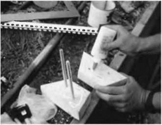
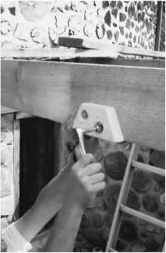
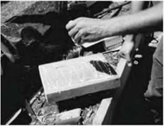
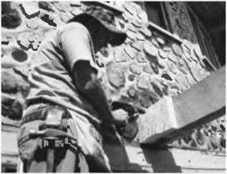
Installation of the header supports was now easy. We glued one side of each piece and inserted the carriage bolt from the non-glued side. Fig. 5.16. This assembly was installed on the joist by tapping the bolts through the three-eights – inch holes. Then the other trapezoid support was installed, glued side against the joist, and the washers and nuts were made fast in the countersink. See Fig. 5.17. The carriage end of the bolt is drawn into the two-by-four, where it will be out of the way of header installation later on.

Подпись: Fig. 5.16, near right: The supports are glued and the carriage bolts installed.
image123

image124Подпись: Fig. 5.17, far right: Doug tightens the hex nut, completing the header support installation.With the supports in place, we’d run slightly long four-by-eight header stock over the top of the joists where it would connect and mark its under­side with a pencil. This eliminated measuring. Using patterns is generally superior to measuring and trying to figure angles. We cut the headers to length with a chainsaw and tried them in place. A good idea in any operation like

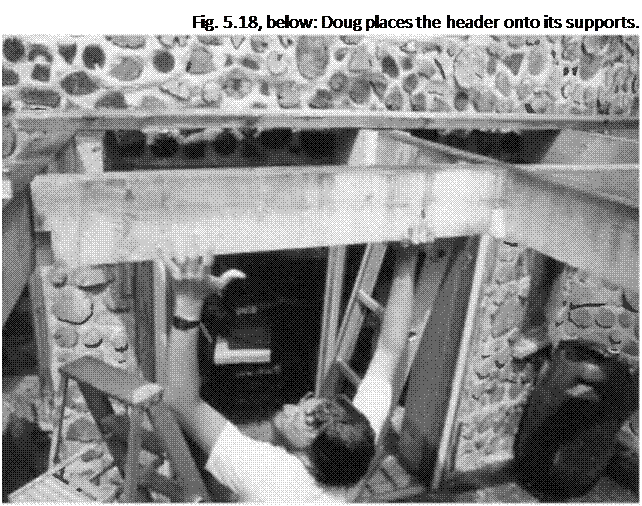
Подпись: Fig. 5.18, below: Doug places the header onto its supports.

this is to always do the longest piece first, it and use it at a shorter location. If you,

If you make a bad cut, you get to re-cut poil the shortest one first, you don’t get a second chance. (“Dagnabbit it! I’ve cut this piece three times and its still too short!” — Old carpenter’s joke.)

If the piece fits, now is the time to cut notches out of each end so that it bears on the header supports. These notches will be 3V2 inches (8.9 centi­meters) high and 1V2 inches (3.8 centi­meters) wide, matching a common store-bought two-by-four stud. If it fits the first time, congratulations! Chances are, though, that you may have to take the piece down and scrape or trim a little to make it fit. Trying and fitting is all part of any kind of timber framing. See Fig. 5.18.

With the headers installed, we can now fasten the secondary joists, the shorter ones whose purpose is to cut the planking span in half Cut one end square, where it will abut the header, and let the other end run long. Always let rough-cut joists and rafters run long on the outside, so that you can snap a chalk-line later and cut them all at one time, all the right length for the

Подпись: Finally, a couple of toenails — from the top, out of sight — will keep the header from wandering. Installing the Secondary Joists Подпись: Fig. 5.19: The floor frame for the new room is completed, and the first two flooring planks are installed.image126overhang. If you cut them the length you think they should be, Mr. Murphys famous law will almost guarantee that you’ll wish you hadn’t. Chalk-lines are like patterns: they are always superior to measuring.

Now is the time to use the simple fastening method alluded to in the previous section. We marked the location of the joist on the header and drilled two seven – sixteenths-inch holes through the wood so that lag screws would meet the end – grain of the joist about two inches from the top and two inches from the bottom—centered right and left, of course. Have someone hold the joist temporarily in place while you tickle its squared end with the drill. Take it down and continue the holes — straight, please — into the end grain of the joist, as deep as is needed for the lag screw used. With a one-half-inch by seven-inch lag screw — plenty strong for the purpose — drill your hole about 23A (7.0 centimeters) inches into the joist. Put a washer under the hex-head of the lag screw and install the bolt. An assistant may have to resist from the other end, to prevent a space occurring between the two members.

Mark and fasten the joist to the girder using one of the methods shown in Figs. 5.12 and 5.13.

The completed floor framework is shown in Fig. 5.19.

Work Begins

Подпись: Fig. 5.7:1 notched the east side eight-by-eight girt to fit it up against the stub of the original four-by-eight rafter. I chiseled and scraped deteriorated wood, back to sound material, and doused the area with a water-sealing product. Note the use of Sill Sear between the girt and the top mortar joint of the cordwood wall.image115Former Earthwood student Doug Kerr visited for a week to help out on the early stages of the project. He wanted to learn timber framing, but didn’t want to wait for the book. Doug arrived in the evening, and the next morning we tore up the entire front sitting deck, and all of the original four-by­eight deck joists. The post-and-beam frame of the original solar room’s south wall was still in excellent condition.

Подпись:Подпись:image116The east and west walls of the lower story were 16-inch cordwood walls, and, for insulation and architectural purposes, we wanted to maintain that same width and style in the new addition. I chose to install new cedar eight-by-eight girts where the old deteriorated doubled four-by-eights had been removed. The south end of the eight-by-eight would be supported directly by the six-by-ten girder that ran along the south side of the original solar roof. But how would we fasten the northern ends of these girts? Improvisation. There was enough of a stub on each of the original four-by-eight floor joists to fasten to, as seen in Fig. 5.7. With my chainsaw, I removed a 4- by 4-inch by 8-inch-high (10.i – by 10.1-centimeter by 20.3-centimeter-high) chunk of wood from the new cedar girt, and fastened it to the stub using two seven – inch (180-millimeter) lag screws.

Remember that the cordwood wall would also be supporting this girt all along its length. Fig. 5.8 shows the east wall girt being installed.

situations. The center floor joist had only 6V2 inches 16.5 centimeters) of good sound four-by-eight extending from the wall. As it was the center joist, maintaining symmetry was important. In this case, we used a wooden gusset system, the gussets made from two scrap pieces of two-by-eight material, each about a foot long. In Fig. 5.9, I apply wood glue to one side of one of the gussets. In many instances, gussets are made of plywood, such as with homemade trusses. I didn’t have plywood at the ready in this case, and, as the join would be exposed, I figured that the two-by-eight pieces would look better anyway. Gussets used in this fashion must be used in pairs, one each side of the joint, just like truss plates on trusses. Otherwise, most of the strength of the joint is lost.

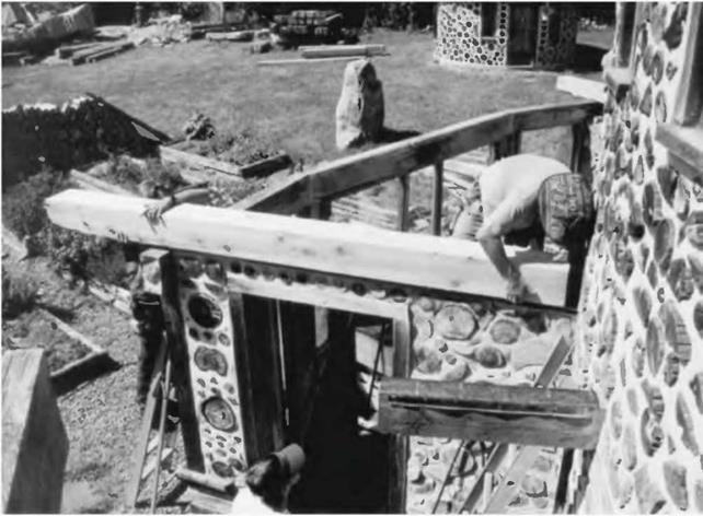
Подпись: Fig. 5.9: Glue is applied to the gusset. image117Подпись: Fig. 5.10: Gussets are screwed and glued to the joists, with half of the gusset on each side of the join.image118Подпись: Fig. 5.11: Doug tightens a hex nut up to a washer on the threaded end of one of the bolts. As Doug looks at the stub, he is installing a bolt at the upper left and lower right of the stub, keeping about three inches from all edges. The carriage end of the bolt is on the other side of the unit, and is drawn into the new four-by-eight by tightening the nut. We countersunk the nuts and washers, so that we could use 8- inch bolts without the threaded end protruding from the joist.image119In Fig. 5.10, I used an electric drill to mount the glued gusset to the two four – by-eights which are butted together. I used four screws on each side of the joint. Half of the gusset (six inches or 15.2 centimeters) was screwed and glued to the original stub, and the other half was similarly fastened to the new joist. The gusset on the other side got the same treatment.

The remaining two joist extensions were a different situation, so we used a different solution. The original joists extended into the space about eighteen inches (45.7 centimeters), and symmetry was not an issue, the way it was in the center. So in this case, we simply fastened the new four-by-eight alongside of the original member, using glue and two strong one-half-inch by 8-inch (1.2- by 20.0-centimeter) carriage bolts. Carriage bolts have rounded heads and a square section just under the head that grabs the wood by pressure and friction. The trick

here is to join the rafters together temporarily while a half-inch hole is drilled all the way through both. There are a variety of clamps that will work for this purpose, or you can temporarily toe-screw the two pieces together while you drill. Again, glue between the pieces makes for a stronger joint. In our case, I used just two large bolts to make the joint. See Fig. 5.11.

Подпись: Fig. 5.12: The author toe-screws the four-by-eight joist to the six- by-ten girder.Подпись: Fiig. 5.13: A right angle fastener can take the place of toenails or toe-screws.image120Fastening the Joist to the Girder

The nice thing about wide joists like four-by-eights and five-by-tens is that they are stable when supported by a wall or girder, unlike two-bys, which can fall over quite easily. Cross-bracing or bridging of two-bys is not only prudent, but building codes require it.

Another nice thing about heavy joists is that they are esthetically pleasing, particularly when the depth of the timber is twice as great as its breadth.

Four-by-eights are very stable over the girder, but they must still be fastened, so that they don’t slide laterally. In Fig. 5.12,1 am toe-screwing the joist to the six – by-ten girder. In Fig. 5.13, I use a right-angle galvanized plate to hold the joist in its correct position over the girder.

Design Questions and Plans

We had several conversations about the use of the new space, where the door and windows would go, and the like. We agreed that we wanted plenty of south-facing windows and that they would have to be of some opening style with a screen option. We found some excellent Caradco™ double-hung windows at a good price, but what really sold Jaki on them was that both the upper and lower sashes could be rotated 180 degrees for easy cleaning. After all, there would be no easy access to the windows exterior on the second story.

A nagging question was whether or not we would be able to maintain the same i:i2 roof slope in an upstairs addition and still have sufficient headroom. I checked this with my tape measure and found that there would be plenty of headroom, even at the southern end of the extended five-by-ten roof rafters. We proceeded to the design stage.

Подпись: 4 W №
image107 image108

Before tearing the pressure-treated boards off, I used a black crayon to lay out the new room on the outside deck, a great aid in planning. We could visualize and mark all the components in their actual positions. Then, on paper, and using a scale of one-half-inch to the foot, I drew the post-and-beam support structure (Fig. 5.2), and a second plan at the same scale, this one for the replacement four – by-eight system which would serve as the floor support for the new addition. (Fig. 5.3). Note that the primary difference between the upstairs rafter plan and the downstairs ceiling joist plan (apart from timber dimensions) is the way the two different structures support the long planking spans which occur as the extended radial rafters get further apart.

I also drew elevations of all three new sides of the new room, so that I could figure out the windows and door, as well as the post, height. Drawing the extended rafters in scale, and at the correct pitch, showed the post height, and these figures could be checked on site with actual measurements. (Figures 5.4, 5,5 and 5.6). I submitted my plans, along with the $15 fee, to the towns building inspector, and got a permit, an important step.
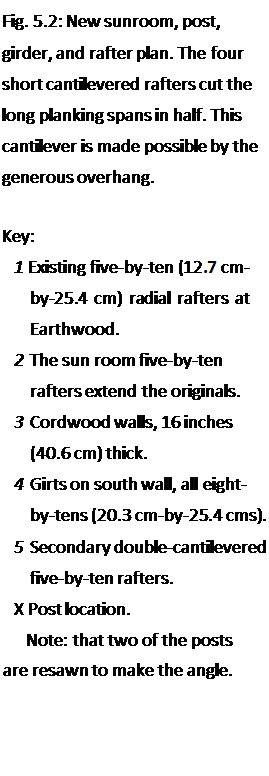
Подпись: Fig. 5.2: New sunroom, post, girder, and rafter plan. The four short cantilevered rafters cut the long planking spans in half. This cantilever is made possible by the generous overhang. Key: 1 Existing five-by-ten (12.7 cm- by-25.4 cm) radial rafters at Earthwood. 2 The sun room five-by-ten rafters extend the originals. 3 Cordwood walls, 16 inches (40.6 cm) thick. 4 Girts on south wall, all eight- by-tens (20.3 cm-by-25.4 cms). 5 Secondary double-cantilevered five-by-ten rafters. X Post location. Note: that two of the posts are resawn to make the angle. The plans also made it easy to generate a materials list, which, in April, I brought to two sawmills for bid. We accepted the slightly higher bid because of quicker and more reliable delivery. This gave the timbers more drying time, and the decision seems to have been a good one, as we have not experienced egregious

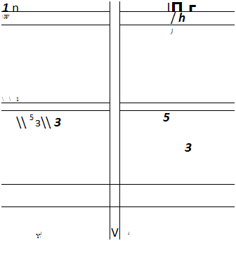
Fig. 5.3: The floor joists for the new room (which are also the ceiling joists for the old one) have four transverse headers to support one end of the short secondary joists. A self-supporting cantilever was not possible at this level in the way that it was for the roof
Подпись: 1 n l П г  W / h \1 } \ 5 з\ 3 5 3 Y1 V 1 Подпись: 4Подпись: 4rafters.

Key:

1 Existing four-by-eight (Ю. І cm – by-20.3 mm) radial joists at Earthwood.

2 Eight-by-eight (20.3 cm-by-

20.3 cm) cedar girts newly installed at top of existing cordwood wall.

3 Replacement four-by-eight joists, married to house joists.

4 Secondary four-by-eight joists cut planking span in half.

5 Headers, all four-by-eights.

6 South wall girts or girders, all eight-by-tens (20.3 cm-by-25.4 cms).

7 Cordwood walls, 16 inches (40.6 cm) thick. Cordwood walls under south-facing windows (see Fig. 5.6) are 8 inches (20.3 cm) thick.
Design Questions and Plans

Fig. 5.4: East elevation, with door.

Key:

1 Five-by-ten (12.7 cm-by-25.4 cm) rafter.

2 Eight-by-ten (20.3 m-by-25.4 cm) girt or girder.

3 Eight-by-eight (20.3 cm-by – 20.3 m) post.

4 Eight-by-eight cedar girt.

5 Four-by-eight (10.1 cm-by-20.3 cm) doorframe.

6 Typical cordwood masonry infilling.


image109

Подпись: П

image111,image112 Подпись: 4 image113,image114 Подпись: p VO

E____ □____ D

Key:

1 Primary five-by-ten (12.7 cm-by-25.4 cm) rafters

2 Secondary (short) five-by-ten rafters

3 Eight-by-ten (20.3 cm-by-25.4 cm) girts

4 Eight by eight (20.3 cm-by-20.3 cm) posts, six feet long

5 Six-by-eight (15.2 cm-by-20.3 cm) posts, cut at an angle to make the bend in the south wall (See Fig. 5.2)

6 Eight-by-eight cedar girt

7 Existing lower story framework

8 Two-by-six (3.8 cm-by-14.0 cm) tongue-and-groove planking

9 Eight-by-eight beam pieces as snowblocking

10 42-inch-wide by 48-inch-high (107cm by 122 cm) double-hung windows

11 46-inch-wide by 48-inch-high (117cm by 122cm) double-hung windows

wood shrinkage. The heavy timbers, as listed, cost about $760. This list is given as an example only. Adjustments were made, so it may or may not serve as an accurate materials list to build a similar sunroom. The “purpose” column matters little to the sawyer, but will be helpful to you when you try to figure out what all these pieces are for.
Подпись:The flooring and roofing two-by-six tongue-and-groove planks are not included. We needed about 850 board feet of these, which cost us $773.

7

1

1

4

1

7

8

6

4

1

2

2

4

Timber Schedule for Earthwood Sunroom

(all white pine except as noted)

Dimensions

Length

5" x 10" (12.7×25.4 cm)

10′ (3 m)

8" x 10" (20.3×25.4 cm)

12′ (3.6 m)

8" x 10" (20.3×25.4 cm)

14′ (4.3 m)

8" x 8" (20.3×203 cm)

14′ (4.3 m)

6" x 8" (15.2 x 20.3 cm)

14′ (4.3 m)

4" x 8" (10.1 x 20.3 cm)

10′ (3 m)

4" x 8" (10.1 x 20.3 cm)

8′ (2.4 m)

1" x6" (2.5 x 15.2 cm)

8′ (2.4 m)

111 x 10" (2.5×25.4 cm)

12′ (3.6 m)

Iм x 12" (2.5×30.5 cm)

10′ (3 m)

2" x 8" (5.1 x 20.3 cm)

12′ (3.6 m)

(The following pieces shall 1

8" x 8" (20.3 x 20.3 cm)

10" (3 m)

2" x 8" (5.1 x 20.3 cm)

8" (2.4 m)

Purpose

Rafters (2 cut in half)

Main (center) south wall girt

Right and left south wall girts (cut into 2 @ 7′).

Posts (when cut in half)

Posts (when cut in half)

Floor joists (2 cut in half)

Doorframes (1 for lintel, 1 extra)

Cordwood key pieces and other Broaden lower story girders Finish interior of lower story posts South wall window framing n white cedar)

East and west downstairs wall girts West wall window framing

An eraser is one of your most valuable tools. Figure out the structure and jointing details on paper, ahead of time. Erasing and redrawing a few lines at the design stage can save major headaches later on. If you can’t visualize the situation from paper plans, build a scale model, a great way to figure out how things are connected. If you can’t build the model, maybe you shouldn’t try to build the real thing.

I have deliberately described the order of events we followed, because it is typical of any building project, large or small. It all starts with conceptualization of the project, which should involve all of the interested parties. This is followed by more detailed drawings, securing a building permit, and, finally, the pricing and procurement of materials. After all that is done…

Case Study: The Sunroom at Earthwood

I

’ve been practicing “timber framing for the rest of us” since 1975, but I never thought I’d write a book about it, so I wasn’t careful about photographing the methods. When students at Earthwood said they really wanted a book on the subject, Jaki and I decided to build a second-story sunroom. We didn’t really need the space, but figured that it would be a great photo opportunity for the book. Also, the ceiling was leaking in the room below the existing sitting deck and we needed a project for cordwood workshops, so we figured we had enough reasons build it. Now it’s our favorite room, especially on sunny winter days.

With the book in mind, I deliberately used a variety of timber-framing techniques.

Design Overview of the Project

I have renovated old houses and started from scratch building new ones. Starting from scratch is easier.

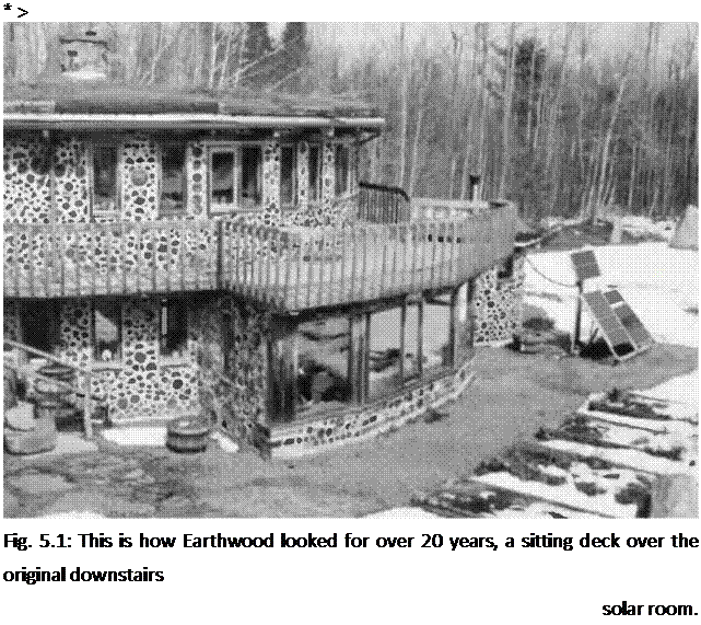
We built a downstairs solar room within a year of Earthwood’s completion in 1981. (Fig. 5.1). The room shared a common wall with the curved cordwood masonry wall of the home, the curvature flattened somewhat by a six-foot-wide (1.8-meter-wide) sliding glass door. The east and west walls feature cordwood, a door, and a small window. The long well-posted south wall is mostly thermalpane glass. A six-by-ten girder — or girt — supported the radial four-by-eight ceiling joist system which extended through the solar room. These joists also supported an outdoor sitting deck of two-by-six pressure-treated planking. Between the ceiling joists, we had installed corrugated fiberglass panels, gently sloped to the south. Rainwater dripping through the deck boards fell onto the panels and was carried away, where it dripped harmlessly onto a crushed stone walkway below. For insulation, we installed extruded polystyrene to the underside of the ceiling joists.

All of this worked fine for a few years, but mice found their way into the space over the insulation, as they are wont to do in the country, and, after a while, the corrugated fiberglass began to leak slightly. After twenty years, the insulation was smelly and in bad shape, a combination of mouse mess and moisture. Something had to be done, whether we built a new room over the top or not.

Подпись: * > Fig. 5.1: This is how Earthwood looked for over 20 years, a sitting deck over the original downstairs solar room. Jaki and I tore out the rigid insulation and the one-by boards that supported it, only to discover that the four-by-eight joists were in bad shape. One or two of them might have been saved, but we decided to replace the lot. The new ceiling joists would be left uncovered — insulation would not be necessary with a finished room upstairs — and we wanted the room to look nice. New tongue-in-groove planking might as well be supported by fresh-smelling and unstained ceiling joists. Building the new sunroom also meant reclaiming the old one, doubling the advantage of space gained.
Joes Rocket Research Landing Pad – A Photo Essay

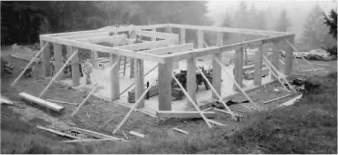
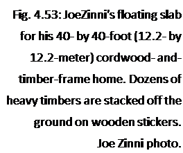
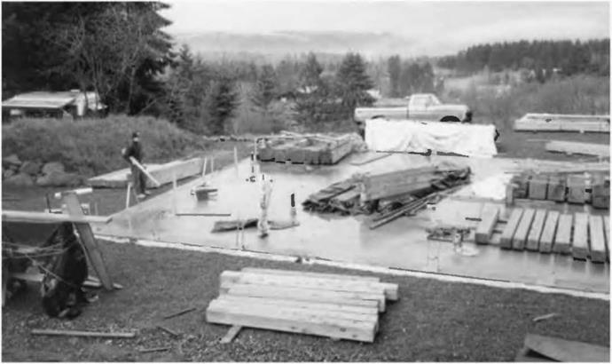
Joe Zinni, like Larry Schuth and Mark Powers, is a former cordwood masonry student at Earthwood. He and his wife Glenna found a 1.25-acre piece building lot they liked in Tenino, Washington, an area where local sawmills are cutting lots of very large timbers. Joe described a friend’s sawmill to me: “Rob, picture a giant Wood Mizer mill, except with a band saw blade eight inches wide and a quarter inch thick, and a throat about six feet across. You wouldn’t believe the size of the timbers they run through there.” In a letter, Joe listed some timbers he has lying around. One is a 16- by 32-inch by 40-foot (40.6- by 81.3-centimeter by 12.2- meter) beam. Another is 13- by 40-inch by 36-feet long. He’s got a half dozen beams measuring 12- by 26-inches by 40 feet. The mind boggles. I have megalithic fantasy dreams about the structures I could design around these behemoths.

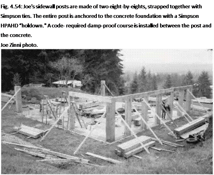
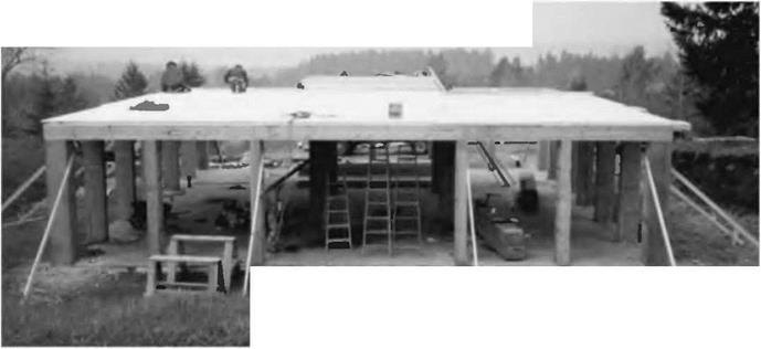
His own house is 40 feet (12.2 meters) square and framed with large timbers: twelve-by-twelve corner posts, eight-by-sixteen sidewall posts (built up from two eight-by-eights strapped to each other, side by side), a double course of six-by­twelves as girts above the posts, and two rows of eight-by-sixteen girders running through the house to shorten ceiling joist spans. The joists themselves are six-by – twelves, and they support two-by-six tongue-in-groove planking. Once the deck was on, the place had become somewhat of a local legend, like a Neolithic “Woodhenge.” As “Woodhenge” probably wouldn’t mean a lot to locals, Joe put up a sign outside the project which all could understand: Joe’s Rocket Research Landing Pad.

Because of high earthquake potential, the building codes in Joe’s area insist on a strong foundation-to-roof tie system. Joe used off the-shelf Simpson strap ties, and, in exposed areas, heavy angle-iron brackets. His fine pictures (Figs. 4.53—4.62) tell the story.

image96

Fig. 4.55: Corner posts are full – sized 16- by 16-inch (40.6- by 40.6-centimeter) timbers. Girts connecting the tops of the posts are six-by-twelves. Joe joined the girts at the corners with 45-degree miter cuts, a nice detail. Each post is well-staked to the ground, and the top girt is eyeballed straight.

Joe Zinni photo.

Подпись: Fig. 4.53: JoeZinni's floating slab for his 40- by 40-foot (12.2- by 12.2-meter) cordwood- and- timber-frame home. Dozens of heavy timbers are stacked off the ground on wooden stickers. Joe Zinni photo. image97Подпись: Fig. 4.54: Joe's sidewall posts are made of two eight-by-eights, strapped together with Simpson ties. The entire post is anchored to the concrete foundation with a Simpson HPAHD “holdown." A code- required damp-proof course is installed between the post and the concrete. Joe Zinni photo.

Fig. 4.56: joe Zinni fastens one six- by-twelve timber to another with two large lag screws, joe Zinni photo.


Fig. 4.57: The basic post and beam frame is almost completed.

Joe Zinni photo.


Fig. 4.58. joe’s Rocket Research Landing Pad is ready for a rocket to land. The plank roof will receive the roof trusses, joe Zinni photo.


image99image100image101

image102

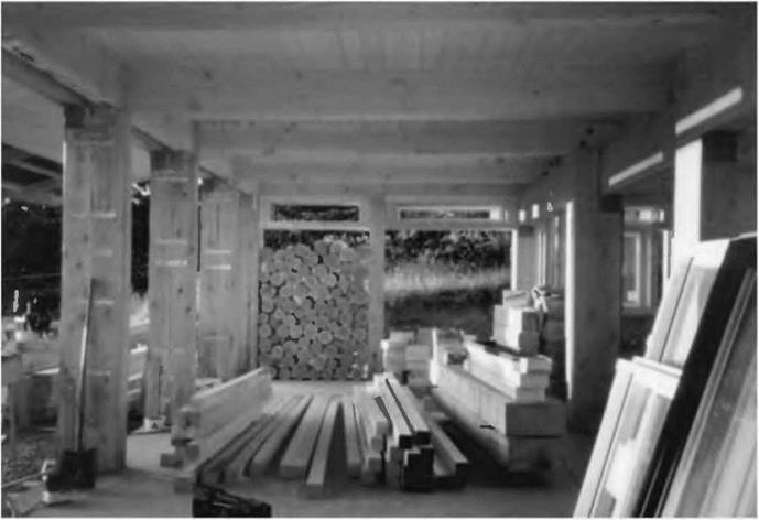
Fig. 4.61: Interior, during construction. Doubled eight-by- eight posts on left. Solid 16-by-16 posts on right. Doubled six-by­twelve girts on left. Single six-by­twelve girders on right. Six-by­twelve ceiling joists support the plank roof. This entire heavy-duty flat "landing pad" supports a truss system for the metal roofing.

Joe Zinni photo.

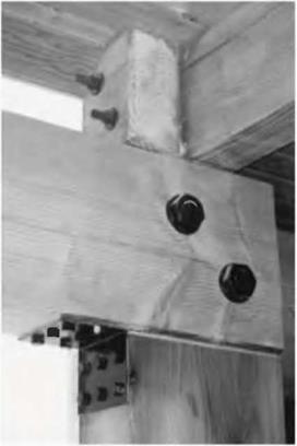
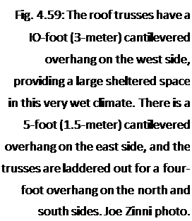
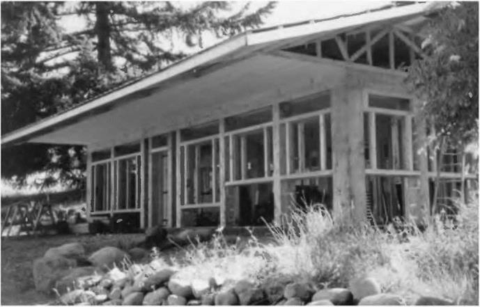
Подпись: Fig. 4.59: The roof trusses have a Ю-foot (3-meter) cantilevered overhang on the west side, providing a large sheltered space in this very wet climate. There is a 5-foot (1.5-meter) cantilevered overhang on the east side, and the trusses are laddered out for a four- foot overhang on the north and south sides. Joe Zinni photo.image103Подпись: Fig. 4.60: Interior detail. Two six-by-twelve girders join over a post, and are bolted together. The heavy metal right-angle connector ties the girders to the post. All exposed metal is enameled black. Ceiling joists are supported by the girders and are joined together by going by each other over the girder, and then fastened together with one- half-inch bolts. Joe Zinni photo.image104

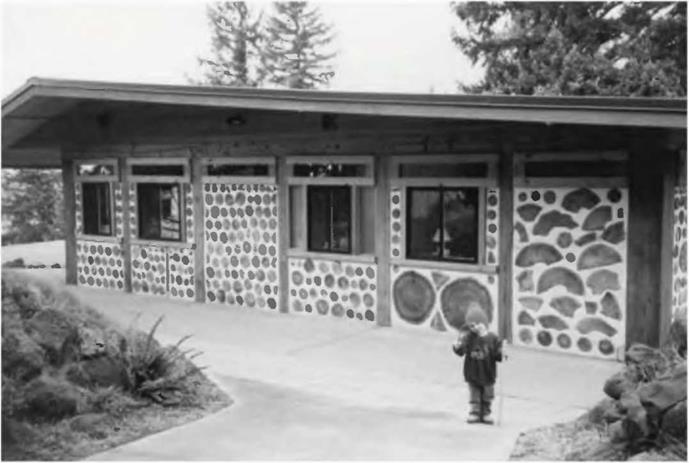
image105Fig. 4.62: The Zinni’s completed home, with cordwood infilling.
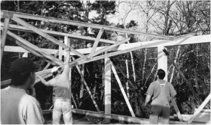
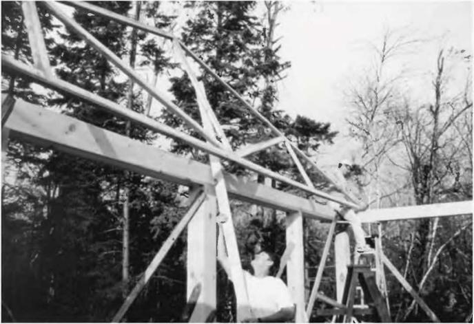
The trusses hove two different pitches on their top chords. Young Sage Zinni looks like a leprechaun next to this massive structure.

Joe Zinni photo.

Insulating Plank and Beam Roofing

Insulating a plank-and-beam roof is a little different than other styles without exposed beams. Log End Cottage had a fairly steep roof, with a slope of about eight-in-twelve (8:12). In that home, the “beam” component consisted of full – sized recycled three-by-tens. We planked over this with ordinary one-inch planking from the sawmill, planed one side for regularity of thickness, as well as for smoothness and appearance on the exposed interior. To insulate, we created a “double roof.” On the topside of the planking, over each of the three-by-tens, we installed a plastic vapor barrier and then another rafter made from a full-sized two-by-six.

We insulated between the two-by-six rafters with fiberglass batt insulation, and then installed a second layer of one-by planking, upon which our roofing material was affixed. This worked pretty well, but I made a couple of mistakes. First, I didn’t vent the space properly. Installed correctly, there should be about two inches of air above the fiberglass batts, and this space should be vented from below, at the eaves, by way of soffit venting, and at the ridge by a ridge vent, a fairly standard item used on peaked shingled roofs of this kind. Allowing for the vented air space above the insulation, I would have needed two-by­eights for the topmost rafter system. Second, we should have immediately closed off the soffits (space between rafters at the eaves) with rodent-proof

venting, such as quarter-inch grid wire mesh (also called hardware cloth), or wooden soffits with soffit vents made for the purpose — another common item at building supply yards. As it was, we had squirrels living in our roof during the three years we lived at the Cottage. They are fairly irritating, although, from their point of view, I should imagine that they were cozy through the winter.

Shallow-pitched plank and beam roofs can be insulated in the same way as a steeply pitched roof, but I much prefer the use of rigid foam insulation
with shallow-pitched roofs, and I’ll show you how we did this on our new addition, the “case study” subject of the next chapter.

I’ll conclude this chapter with an impressive example of an owner-builder employing timber framing techniques “for the rest of us.”

Plank and Beam Roofing

“Plank and beam” roofing consists of planks — often tongue-in-groove — supported from below by exposed beams, or rafters. This is the system we used at Log End Cottage, Log End Cave, and Earthwood, and it is my favorite roof support system for three reasons:

i. We like the aesthetic appeal of exposed beams, with light- colored V-joint tongue-in­groove planking above them.

Fig. 4.46: The trusses are temporarily stored upside down, straddling the sidewalls.


image90

image91Подпись: 2. Plank and beam roofing is strong. For example, two-by-six tongue-in- groove planking — on four-foot centers — will support a 185 PSF (pounds per square foot) earth roof load, providing that the beam framework is engineered correctly. With conventional roof loads, planking spans of six feet and even eight feet are possible. Fig. 4.52 shows a strong homemade truss system, with the tension and compression web members sandwichedFig. 4.47: Chris started with the second truss from the end, well braced to the ground. The first and last trusses, called the gable trusses, have overhangs built into them, which makes them more difficult to deal with. After all the other trusses are braced firmly in place, the two gable trusses are installed. The 24-inch centers are already marked on the sidewall girts, and each truss is given exactly the same overhang at each end. Once the overhang has been determined at both ends of the first truss, the others can be marked exactly the same. Before the crew arrived, Chris made sure that his sidewalls were straight and well-braced from the sides.
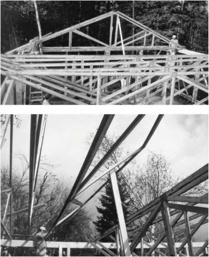
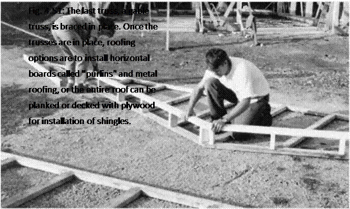
Fig. 4.48: With a long two-by-four fastened near the top of the truss with a pivot nail, Chris raises the point of the truss to vertical. The two helpers set it on the 24-inch center marks, and communicate with each other about the overhang. Toenails fasten the trusses to the doubled two-by – eight girts, but the trusses are also temporarily cross-braced to each other, so that they don’t go down like so many dominoes.


Fig. 4.49: The third truss is raised.


image92

between doubled top and bottom chords. Note the wide planking spans and the attractive heavy metal truss plates.

Incidentally, building up a frame with bolted timbers, as in this picture, is another great framing system, but beyond the scope of this book. Called the Walter Segal timber frame method, it has become very popular with owner-builders in the United Kingdom. The method is covered very well in Out of the Woods: Ecological Designs for Timber Frame Housing, listed in the Bibliography.

Подпись:

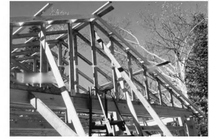
image93 Подпись: Fig. 4.50: Chris and his wife, Kat, make and install the "ladder” to the two gable trusses, to provide an overhang. Note that the gable trusses have lots of vertical members, instead of the angled tension and compression chords. With the ladder and number of vertical members, these trusses are probably about twice as heavy as the others. They can be installed after the other trusses are well- braced to each other.

image943. Plank and beam roofing is easy to do. Nailing goes quickly because normally, the installer is nailing into fairly wide beams. You’ve almost got to try to miss the beam to do so.

Once the plank-and-beam roof is engineered, installation is as easy as installing the rafters, then nailing down the planking.