Category Timber Framing for the Rest of Us Rob Roy

Appendix В: Stress Load Calculations for Beams

S

pan tables, like the one in Appendix A, will serve for roof design with most structures. With heavy roofs, such as earth roofs, adequate tables are very hard to find. This Appendix shows how to check the girders and rafters in a heavy roof design for shear and bending. Once you have followed through the example, and understand where all the numbers have come from, you should be able to use the formulas and procedures to check other rectilinear designs. Two other books with good information about calculating beam strength are A Timber Framer’s Workshop and Homing Instinct, both listed in Appendix C.

Using this Appendix requires familiarity with basic algebra, specifically the ability to substitute numbers for letters in a formula, and to solve for a single unknown. It is important to keep track of the units (feet, pounds, etc.) as you solve the equations. Please read Chapter 2: Basic Timber Frame Structure, before using this Appendix.

Problem: Test the 40- by 40-foot Log End Cave Plan for the shear and bending strength of the rafters and girders as designed. (The posts and planks are the strong — in some ways overbuilt — components of this design, as discussed in Chapter 2.) A portion of the plan, enough for our purposes, is shown in Fig. A2.1. Girders are labeled “beams” on the plan. The plan is based upon simple 10- foot-square sections, repeated sixteen times, like a chessboard with just four squares on a side. Only six complete sections are shown in the portion reproduced here. Here are the givens:

Design Load:

Earth roof, saturated; 8 inches at io pounds/inch/SF………………………………………………………………………………………. 80 pounds/SF

Crushed stone drainage layer; 2 inches at 10 pounds/inch/SF………………………………………………………………………………………. 20 pounds/SF

Snow load by code, Plattsburgh, NY………………………………………………………………………………………. 70 pounds/SF

Structural load, typical for scale of heavy timber structure

(includes timbers, planking, membrane, and insulation) ……………………………………………………………………………………….. 15 pounds/SF

Total maximum load……………………………………………………………………………………… 185 pounds/SF

Kind and grade of wood:

Different species of woods have different stress load ratings, and the lumber grade has a large impact on the ratings, too, as can be seen from these few examples from Architectural Graphic Standards:

Type of wood

Grade

fb1

fT

Douglas Fir, Inland Region

Select Structural

2,150

145

Douglas Fir, Inland Region

Common Structural

1,450

95

Eastern Hemlock

Select Structural

1,300

85

Eastern Hemlock

Common Structural

1,100

60

Southern Pine

#1 Dense

1,700

150

Southern Pine

#2

1,100

85

1 unit stress for bending in pounds per square inch

2 unit stress for shear in pounds per square inch

For our example, all timbers are assumed to be Douglas Fir (Inland Region, Common Structural) with the following stress load values:

Unit stress for bending (fb) of 1,450 pounds per square inch Unit stress for horizontal shear (fv) of 95 pounds per square inch

These are moderate values, incidentally, similar to Eastern spruce and red and white pine. See Architectural Graphic Standards, The Encyclopedia of Wood, A Timber Framers Workshop and other engineering manuals for stress load ratings for a variety of woods.

Cross-sectional dimensions (b and d): Fig. A2A: A portion of the 40′ x

• Rafters are “five-by-tens,” that is, they are five inches (12.7 cm) in breadth 40′ Log End Cove plan.

(b) and ten inches (25.4 cm) in depth (d).

• Girders (“beams” on the plan) are “eight-by-twelves,” that is, they are eight inches (20.3 cm) in breadth (b) and twelve inches (30.5 cm) in depth (d).

Frequency (spacing):

• Rafters are 30 inches o. c., that is: 30 inches (76 cm) is the center-to-center spacing for adjacent members.

• Girders are io feet o. c., that is: ten feet (3 m) is the center-to-center spacing between parallel girders or between girders and the side walls.

Span (L):

• Spans are nominally ten feet (3 m) for both girders and rafters. Actual clear spans, from the edge of one support to the edge of another, is closer to nine feet (2.75 m), but 10 feet is the number used in place of L (span) in the example.

Nomenclature:

• “Beam” refers to both rafters and girders

• “Simple Span” means that a beam is supported only at its ends. For example, the top half of Fig. 2.10 on page 24 shows two simple-span beams.

• “Double Span” means that a beam is supported at its ends, and also at its midpoint, as in the bottom half of Fig. 2.10.

A = Cross-sectional area (b times d) of beam in square inches b = Breadth of beam, in inches d = Depth of beam, in inches

fb = Allowable unit stress for bending in pounds per square inch fv = Allowable unit stress for shear in pounds per square inch L = Length of span in feet

M = Bending moment in foot-pounds or inch-pounds Mx = Bending moment at the two midspans on a double-span beam

PSF = pounds per square foot
R = Reaction at supports

S = Section modulus of cross-section of beam in inches cubed V = Total shear allowable or actual w = Load or weight per linear foot on beam, in pounds W = Total uniform load or weight on beam, in pounds

Algebraic operations:

/ = The division sign. The value before the division sign is divided by the value after it.

6(8) = 48 or (6)(8) = 48 means “6 times 8 equals 48.” The “times” sign is implied.

bd = A means “b times d equals A.” Again, multiplication is implied.

Formulas used with Simple-Spans:

R = V = wL/z M = wL/8 S = bd2/6 s = M/fb fv = 3V/2A V = wL/z

Formulas used with Double Spans:

Rj = Vj = R3 = V3 = 3WL/8 R2 = 2V2 = iowL/8 V2 = 5WL/8 Mx = 9wL2/i28

We have now listed the five variables for structural design for shear and bending, as discussed in Chapter 2, and we have all the nomenclature and formulas that we need. Now we want to find out if the structure as designed — particularly the rafters and girders — is of adequate strength for both shear and bending to support the design load of 185 pounds per square foot (903 kilos per square meter).

i. Calculating roof load for bending for rafters, simple-span.

(That is, all rafters are about ten feet long, and join over girders.)

S = bd2/6 = (5")(io")2/6 = 83.3 in3 (Section modulus is measured in “inches cubed”)

fb = 1,450 psi (pounds/square inch), given above for Douglas Fir, Inland Region, Common Structural

S = M/fb. By transposition: M = S(fb) = 83.3^(1450 lb/in2) = 120,785 in. lbs

This is the bending moment in “inch-pounds”. To derive the more convenient “foot-pounds,” we need to divide by 12 in/ft, because there are 12 inches in a foot. So:

120,785 in. lbs divided by 12 in/ft = 10,065 foot-pounds L = 10′ (given). M = wL2/8. By transposition: w = 8M/L2 Substituting for M and L: w = 8(10,065 ft lbs)/ioo ft2 = 805 lbs/ft

That is: 805 pounds per linear foot. We haven’t got pounds per square feet quite yet. If rafters were on 12-inch centers, they could support 805 pounds per square foot (3,930 kilos per square meter). A linear foot would translate to a square foot in this special case. But our example calls for rafters on 30-inch centers, so we need to make the following adjustment:

i2"/sq. ft. divided by 30" = 0.4 ft.(8o5 lbs/ft) = 322 PSF allowable

Think of it this way: There are only 40 percent (0.4) as many rafters on 30- inch centers as on 12-inch centers. As the impact of frequency is a direct proportional relationship to strength, the rafters on 30-inch centers will support only 40 percent of the load, everything else remaining the same.

The specified rafters, on simple span, will easily support the 185 PSF required.

Now lets try it on a double span. We’ll use 20-foot-long rafters, supported at each end, but also at the middle by a girder.

2. Calculating roof load for bending for rafters, double-span. (That is,

all rafters are about twenty feet long, and supported at midspan by a

girder.)

Maximum allowable bending moment (M) = 10,065 foot pounds, from calculation (1) above.

Mx = Bending moment at the two midspans on a double-span beam

Mx = 9WLY128 (from formulas above)

W = 128 Mx /9L1 w = 128(10,065 ft. lbs.)/9(io ft)2 = 1431 lbs./ft

Again, this is “pounds per linear foot.” We make the same adjustment that we made at the end of calculation (1) above:

i2"/sq. ft divided by 30" = 0.4 ft.(i,43i lbs/ft) = 572 PSF allowable

Using a single 20-footer, supported halfway, increases bending strength by quite a bit, but this value is far stronger than it needs to be. Now, lets test rafters for shear.

3. Calculating roof load for shear on simple-span.

fv = 95 psi (pounds/square inch), given above for the same grade of Douglas Fir

A = bd = 5"(10") = 50 inches squared (In this case, the same as “square inches.”)

fv = 3V/2A. By transposition: V = 2Afv /3 = 2(50 in2)(95 lbs)/3(in2) = 3,167 pounds maximum allowable (V is “total shear allowable”)

V = wL/2. So, w =2V/L = 2(3,167 lbs)/io feet = 633 pounds per (linear) foot

But, again, rafters are not on 12" centers, but are actually 30 inches o. c. Making the adjustment: 12"/30" = 0.4 0.4(633) = 253 PSF allowable, another good strong number.

4. Calculating roof load for shear on a double-span rafter.

Maximum allowable shear (V) = 3,167 pounds from calculation (3) above. Shear at ends (Rj and R3): V = 3wL/8. Transposed: w = 8V/3L W = 8(3,167 pounds)/3(io feet) = 845 pounds per lineal foot Rafters are 30 inches o. c., so: = 0.4; 0.4(845) = 338 pounds per

square foot

That is the shear strength at the ends, at Rt and R3. But, at R2, the center support, the situation is a little different:

Shear at middle (R2): V = 5WL/8. Transposed: w = 8V/5L W = 8(3,167 pounds)/5(io feet) = 507 pounds per lineal foot Rafters are 30 inches o. c., so: = 0.4; 0.4(507) = 203 PSF, still more

than the 185 PSF foot required.

Now let’s do the girders, and we’ll just do them for single-span because 20- foot-plus eight-by-twelve girders are really a bit extreme. Plus, as we know, they will not only be easier to install as two io-footers, but the shorter pieces will actually be stronger on shear.

5. Calculating roof load for bending on the single span 8- by 12-inch Douglas fir girders of this example. The load from the rafters is symmetrically placed along the girder at regular 30-inch spacings, so it is reasonable to use the same formulas we used for single-span rafters.

S = bd’/6 = (8")(i2")2/6 = 192 in3 (Section modulus is measured in “inches cubed”)

fb = 1450 psi (pounds/square inch), given above for Douglas Fir, Inland Region, Common Structural

S = M/fb. By transposition: M = S(f^) M = 192^(1,450 lb/in1) = 278,400 in. lbs

This is the bending moment in “inch pounds”. To derive the more convenient “foot pounds,” we need to divide by 12 in/ft, because there are 12 inches in a foot. So:

278,400 in. lbs divided by 12 in/ft = 23,200 foot pounds

L = io’ (given) M = wL2/8. By transposition: w = 8M/L2

Substituting for M and L: w = 8(23,200 ft lbs)/ioo ft2 = 1,856 pounds per linear foot

The girder can support 1,856 pounds per linear foot, or 18,560 pounds in all, if the load is fairly constant along its length. But for what portion of the roof is the girder responsible? Look again at Fig. A2.1. The area AB is the area for which girder A-В is responsible. Area CD is part of the area carried by the girder C-D. Area W is carried by the block wall. The two areas labeled SR are carried by the special rafters labeled Y and Z. Y and Z are special because their loads are carried directly down through the girders to the posts, adding no bending stresses to the girder. The area AB is 10 feet by 7.5 feet or 75 square feet. So, the total allowable carrying capacity of the girder (18,560 pounds in all) divided by the square footage for which it is responsible (75 square feet) results in the allowable load per square foot, assuming an equally distributed load. 18,560 pounds/75 SF = 247.5 PSF. Still a good number, as it is higher than 185 PSF. Now, what about girders on shear?

6. Calculating roof load for shear on the single span 8” by 12" Douglas fir girders of this example. The load from the rafters is symmetrically placed along the girder at regular 30-inch spacings, so it is reasonable to use the same formulas we used for single-span rafters.

fv = 95 psi (pounds/square inch), given above for the same grade of Douglas Fir

A = bd = 6"(12") = 96 inches squared (In this case, the same as “square inches.”)

fv = 3V/2A. By transposition: V = 2Afv /3 = 2(96 in1) (95 lbs)/3 (in1) = 6,080 pounds maximum allowable (V is “total shear allowable”)

To get the shear strength at the ends of a single-span rafter, use:

V = wL/2 So, w =2V/L = 2(6,080 lbs)/io feet = 1,216 pounds per (linear) foot, or 12,160 pounds over 10 feet.

Again, the area for which girder A-В is responsible is area AB, or 75 SF.

12,160 pounds divided by 75 SF results in 162.1 PSF, which is less than the desired carrying capacity of 185 PSF for the earth roof described. It doesn’t look good. However, if we consider that the true girder clear span (between posts) is actually 9 foot 4 inches and substitute 9 foot 4 inches (9.333 ) for 10 feet in w = 2V/L, we get w = 1,303 pounds per linear foot, or 13,030 over 10 feet. Divided by 75 SF results in 173.7 PSF, closer, but still a little short of the mark. What can we do? Shear, unlike bending, is a direct linear relationship. The shortfall can be made up in variety of ways. These will all work:

A. Beef the girders up to 9 inches wide. Now A = 108 square inches instead of 96 square inches. This change increases the cross-sectional area of the girder — and its shear strength — by 12.5 percent because 12/96 = .125. Now, 173.7 PSF times 1.125 equals 195.4 PSF, so we’re good again.

B. Use a wood with a unit stress for horizontal shear at least 10 percent greater than the 95 psi for Douglas Fir (Inland Region, Common Structural). Any wood with an (fv) of at least 105 psi would do nicely.

C. Shorten the girder clear span by 7 inches to 8 foot 9 inches (8.75′). This yields 185.3 PSF, which is fine, as there are great safety factors built into these calculations. Just work to the numbers. You don’t have to add an additional safety factor.

D. If you want to keep the plan as designed, you could always decrease the load by about 12 PSF, down to 173 PSF. Eliminate 1.2 inches of earth or crushed stone. Is this cheating? In point of fact, the stone and earth layers at Earthwood are really about 8.5 inches total, not 10 inches, so our load here is probably about 170 PSF. This is enough to maintain our living roof.

Incidentally, using a 20-foot girder, supported half way, weakens the plan unacceptably in terms of shear strength for the girders. While shear strength increases at the ends to 218 PSF, it decreases over the center support to 130 PSF. Strange, but true. See Fig. 2.10 and the nearby commentary in Chapter 2 under the heading Shear and Shear Failure.

Disclaimer: The author is not an engineer. Use these exercises as a point of beginning, to get you into the ballpark. Always have your plan checked by a qualified structural engineer.

[1] Birch, Yellow. Hard and heavy. Can be stronger than red oak, but can be hard to work. Has a nice wintergreen aroma.

[2] Oak, White. The classic hardwood for timber framing, white oak is strong, durable, and decay resistant. It shrinks a lot, but in exposed rafters, joists, and girders, shrinkage is not really a problem. Sobon and Schroeder (1984) say it is very workable for traditional timber framing, but ten years later, Sobon (1994) says it is “more difficult to work than red oak or beech.” My personal experience is limited to making a few chainsaw cuts to join a ten-by-twelve white oak girder over a couple of eight-by-eight white oak posts. This is not a problem when the timbers are still fairly young. Once hardwoods are fully seasoned, sparks will fly off your chain!

[3] Pine, Red or Norway. Similar strength characteristics as white pine, but in my experience at Earthwood, the red pine twists a lot more than the

[4] The Granberg Mini-Mill. Similar to the Beam Machine, except that it comes with a 12-foot metal guide rail to fasten to a two-by-six plank (not provided), and an extra handle and guide assembly to help pull the

[5] Logosol Timber Jig. My editor for this book, Richard Freudenberger, tested this chainsaw attachment, similar to the Basic Alaskan Mills, and wrote a comprehensive report for BackHome magazine’s September/ October, 2003 issue. In the article, Richard says, “At 5^2 pounds, the Timber Jig is light enough to be carried into the woods with the saw. Yet if you wanted to set up a permanent work site to cut timbers or planks for a building project, it would be a simple matter to make a timber log table to support your logs at a comfortable working height.” Using an aged Husqvarna saw with a displacement of about five cubic inches, and a

[6] Better Built Ripsaw. This mill is also driven by a chainsaw head, but the bar and chain are replaced with a mounted bandsaw mill. In an article in Independent Sawmill and Woodlot Management magazine (August/ September, 2003), author Dave Boyt speaks well of this “simple and economical chainsaw-powered bandmill.” Although very much less expensive than full-sized portable sawmills, the $1,489 cost — plus the chainsaw — may not justify itself in a single project. However, it might be a very good investment for someone who anticipates additional homesteading projects in the future, or simply wants to add value to trees on the woodlot which need to be thinned.

[7] TimberLok™ screws are made by Olympic Manufacturing Group, Inc. listed in Appendix C. They come in a variety of lengths, with the six-, eight-, and ten-inch (15.2-, 20.3-, and 25.4-centimeter) ones the most useful for timber framing applications. Among the advantages over heavier shank screws and large nails, such as log cabin spikes, is that the TimberLok™ screws install faster and require no pre-drilling; they countersink into the beam; they have a corrosive resistant coating that also helps them grip; and they are easily removable. All TimberLok™ screws have a shank diameter of three-sixteenth inch, and a thread diameter of one-quarter inch. For the long screws, it is recommended to use a high-torque, low (450) rpm drill. Olympic supplies a five-sixteenths inch (8 millimeter) hex head bit with each box of screws. My local supplier sells a box of 50 ten-inch TimberLok™ screws for $28.

GRK Canada, Ltd (also listed in Appendix C), makes an even higher-quality — albeit more expensive — screw of a similar kind.

Appendix A: Span Tables

Using Span Tables

Table One is an abbreviated version of Table R502.3.1(2), from the International Residential Code for One – and Two – Family Dwellings. This particular table, just one of many in IRC codebook, is for floor joist spans for common lumber species, and assumes that we are designing for a residential living area with a live load of 40 pounds per square foot (40 PSF), a dead (structural) load of 10 PSF and an allowable deflection of 1/360.

Table Two is an abbreviated form of Table R802.5.1(7), from the International Residential Code for One – and Two – Family Dwellings. This table is helpful in designing rafter spans for anticipated 70 PSF snow loads on a 20 PSF dead load.

Lets do a couple of exercises, using Table Two:

Example 1: If I want rafters to be two-feet (24") on-center, what depth of rafter will I need to accommodate 12-foot spans?

Procedure: Go to the bottom — 24" — portion of the chart and look for spans of 12 feet and over. Only six of the strongest 2" X 10" will do it, the four select structural grades of all woods plus the Douglas fir-larch #1 and the Southern pine, #1. With 2" X 12" rafters — the last column — twelve of the sixteen listed woods will do the trick. Only the #3 grades — the weakest stuff — will not.

Example 2: I’ve scored a great deal on some 2" X 10" Southern pine #1 rafters. What is the greatest rafter span I can support?

Procedure’. Go to the 2" x 10" column and look down until you spot Southern pine #1 for 16" and for 24"on-center spacings. At 16" centers, a span of 14 4" is possible. At 24" centers, the span drops to 13′ 1". These possible spans now need to be balanced against the size (length) of the desired building and the actual number of rafters “scored.” The complete version of these span tables, as the appear in the International Building Code, also includes rafter spacings of 12" and 19.2" (0.5 meter).

Table 1: R502.3.1 (2) Floor Joist Spans for Common Lumber Species

Dead Load =

10 psf

Allowable Deflection = 1/360

2" x 6"

2" x 8"

2" x 10"

2" x 12"

Maximum floor joist spans

Rafter Spacing Species & Grade

(feet & inches)

(inches)

16" Douglas fir-larch SS

10’4"

13’7"

17-4"

214"

Douglas fir-larch #1

941"

134"

16’5"

194"

Douglas fir-larch #2

9’9"

12V"

1515"

1740"

Douglas fir-larch #3

7’6"

9’6"

11 ’8"

13’6"

Hemlock-fir SS

9.9"

1240"

16’5"

1941"

Hemlock-fir #1

9’6"

12V"

16’0"

18’7"

Hemlock-fir #2

94"

12’0"

15’"

17’7"

Hemlock-fir #3

7’6"

9’6"

11 ‘8"

13’6"

Southern pine SS

10’2"

134"

17’0"

20’9"

Southern pine #1

941"

134"

16’9"

20’4"

Southern pine #2

9’9"

1240"

164"

1840"

Southern pine # 3

84"

10’3"

12-2"

14’6"

Spruce-pine-fir SS

9’6"

12’7"

16’0"

19’6"

Spruce-pine-fir #1

9’4"

12’3"

15’5"

1740"

Spruce-pine-fir #2

9’4"

12-3"

15’5"

1740-

Spruce-pine-fir #3

7’6"

9-6"

11 ‘8"

13’6"

24" Douglas fir-larch SS

9’0"

11 41"

15’2"

18’5"

Douglas fir-larch #1

8’8"

11 ’0"

13’5"

15V"

Douglas fir-larch #2

84"

10’3"

12-7"

14’7"

Douglas fir-larch #3

6’2"

7’9"

9’6"

1Г0"

Hemlock-fir SS

8’6"

11 ‘3"

14-4-

17’5"

Hemlock-fir #1

8’4"

10’9"

134"

15’2"

Hemlock-fir #2

741"

10’2"

12-5"

14-4»

Hemlock-fir #3

6’2"

7-9-

9’6"

1l-o"

Southern pine SS

840"

11 ‘8"

1441"

184"

Southern pine #1

8’8"

11 ‘5"

14’7"

17’5"

Southern pine #2

8’6"

11 ‘0"

134"

15’5"

Southern pine #3

6’7"

8’5"

941"

1140"

Spruce-pine-fir SS

8-4-

11 ‘0"

14’0"

17’0"

Spruce-pine-fir #1

84"

10’3"

12-7-

14V-

Spruce-pine-fir #2

84"

10’3"

12-7"

14V-

Spruce-pine-fir #3

6’2"

7-9-

9’6"

1l-o"

Table 2: R802.5.1 (7) Rafter Spans for 70 PSF Ground Snow Load

Dead Load = 20 psf

2" x 4" 2" x 6" 2" x 8" 2" x 10" 2"x12"

Rafter Spacing Species & Grade (feet & inches)

(inches)

Douglas fir-larch SS

6’10"

10’3"

13’0"

1540"

184"

Douglas fir-larch #1

540"

8’6"

10’9"

13’2"

1513"

Douglas fir-larch #2

5’5"

741"

104"

124"

14′ 3"

Douglas fir-larch #3

4’1"

6’0"

7’7"

94"

10’9"

Hemlock-fir SS

6 6"

104"

12’9"

157"

18’0"

Hemlock-fir #1

5’8"

8’3"

10’6"

1240"

1440"

Hemlock-fir #2

54"

740"

941"

124"

144"

Hemlock-fir #3

44"

6’0"

7’7"

94"

10’9"

Southern pine SS

6’9"

10’7"

14’0"

1740"

21 ‘0"

Southern pine #1

6’5"

9’7"

12’0"

144"

174"

Southern pine #2

540"

84"

10’9"

1240"

154"

Southern pine #3

4’4"

6’5"

8’3"

9’9"

117"

Spruce-pine-fir SS

64"

9’6"

12’0"

14’8"

174"

Spruce-pine-fir #1

5’5"

741"

104"

124"

14’3"

Spruce-pine-fir #2

5’5"

741"

104"

124"

14’3"

Spruce-pine-fir #3

44"

6’0"

7’7"

94"

10’9"

Douglas fir-larch SS

6’5"

94"

1140"

14’5"

16’9"

Douglas fir-larch #1

54"

7’9"

940"

12’0"

1341"

Douglas fir-larch #2

5’0"

7’3"

9’2"

1T3"

13’0"

Douglas fir-larch #3

3’9"

5’6"

641"

8’6"

940"

Hemlock-fir SS

64"

97"

11 ‘8"

147"

15’5"

Hemlock-fir #1

5’2"

7’7"

97"

1Г8"

137"

Hemlock-fir #2

441"

77"

94"

114"

1240"

Hemlock-fir #3

3’9"

5’6"

641"

8’6"

940"

Southern pine SS

64"

10’0"

13’2"

16’5"

197"

Southern pine #1

541"

8’9"

1V0"

134"

157"

Southern pine #2

54"

7’7"

940"

1T9"

13’9"

Southern pine #3

4’0"

541"

7’6"

840"

107"

Spruce-pine-fir SS

541"

8’8"

11 ‘0"

1315"

157"

Spruce-pine-fir #1

5’0"

7’3"

92"

1T3"

13’0"

Spruce-pine-fir #2

5’0"

7’3"

9’2"

1T3"

13’0"

Spruce-pine-fir #3

3’9"

5’6"

641"

8’6"

940"

The tabulated rafter spans assume that ceiling joists are located at the bottom of the attic space or that some other method
of resisting the outward push of the rafters on the bearing walls, such as rafter ties, is provided at that location.

Where to Find Span Tables

• Books. Seven of the books in the Bibliography have useful span tables, indicated by the notation (ST) before the entry The International Residential Code for One – and Two-Family Dwellings has span tables that you know will be approved by code.

• The Internet. It is possible to find all sorts of span tables on the world wide web. I searched for span + tables on the popular Google search engine and came up with these excellent websites, among others:

www. southernpine. com/. This is the Southern Pine Council’s website. Click on “Span Tables” for a list of over 40 different floor joist, ceiling joist, and roof rafter span tables using various grades of southern pine. Very comprehensive.

www. cwc. ca/design/design_tools/calcs/SpanCalc2002/index. php/. This is the Canadian Wood Councils Span Calc 2000 program. You can select the member type (rafter, floor joist, etc.), species of wood, grade, dimensions, spacing, and loads. Press “calculate” and the program instantly returns the maximum span. Despite being a Canadian website, the SpanCalc results are only valid in the United States.

www. wwpa. org/. This is the Western Wood Products comprehensive website. Click on “Span Tables Online,” then “Individual Span Tables” and you will have access to dozens of span tables for rafters, floor joists, and ceiling joists. Various western wood species and grades are covered. You will need Acrobat Reader to download these.

The Finished Room

image149Following are some views (Figures 5.41-5.45) and details of the completed sunroom.
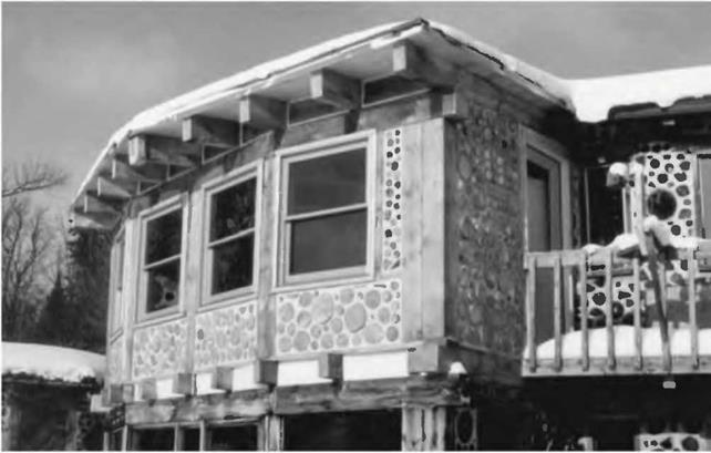
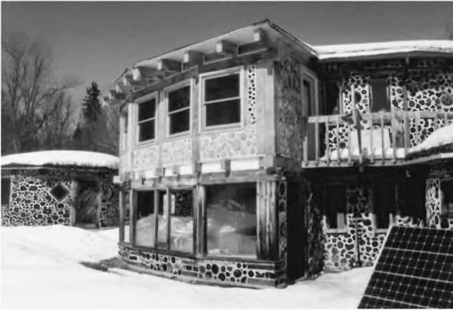
Подпись: Fig. 5.41a & b (detail, below): The completed sunroom at Earthwood. Only the cordwood snow-blocking in the lower solar room remains to be done. We also waited until the spring of 2003 to put the earth on the roof. image150Jaki and I are glad that we have gained a beautiful new room as a result of this book… realizing that we wouldn’t have built it otherwise! In case you’re curious, the materials cost was about $4,000, or $20 per square foot. We also spent $250 on labor. And we also renewed the downstairs solar room at the same time, another 200 square feet, so were quite pleased with the cost. Larger buildings could cost less per square foot, particularly as our sunroom is heavy on windows ($1,243 for five) and an exterior door ($338), expensive items. I believe that a timber-frame home, using techniques described in this book, combined with some sort of natural infilling (cob, cordwood, straw bale, wattle-and-daub, etc.) can still be built today for a materials cost of $15 to $25 per square foot, depending on where you build and how good you are at scrounging materials.
Now I hope that Timber Framing for the Rest of Us will inspire you to build with heavy timbers, joined by simple common-sense techniques and fasteners, and that your results will be every bit as satisfying as ours have been.

just think, “build quality!”

Fig. 5.44, near right: Ceiling and

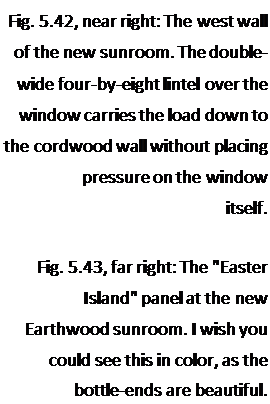
Подпись: Fig. 5.42, near right: The west wall of the new sunroom. The double-wide four-by-eight lintel over the window carries the load down to the cordwood wall without placing pressure on the window itself. Fig. 5.43, far right: The "Easter Island" panel at the new Earthwood sunroom. I wish you could see this in color, as the bottle-ends are beautiful. image151rafter detail.

Fig. 5.45, far right: Joining two rafters with heavy metal plates can be quite attractive.

Closing In

With the timber framing completed, it was time to fill in the wall panels. We used the small lower panels beneath the windows as training panels for students at the building school, but, as we got higher, Jaki and I pandered to a dream which we
have had for a long time: to make the most beautiful and artistic cordwood panels that we’ve ever done. The motif would be our Pacific Rim Journey of 2001, especially our one-week visit to Rapa Nui (Easter Island). The results of our efforts appear in the pictures at the end of this chapter. See my previous book, Cordwood Building: The State of the Art for more about cordwood masonry

Windows and doors. I don’t want to spend a lot of time on windows and doors. There are myriad choices. The most important consideration with respect to the subject matter of this book is that you may wish to frame the windows — and doors — with your heavy-timber posts and beams. This must be worked out carefully at the design stage. Know the rough opening (R. O.) of the windows and doors you plan to use, but don’t trust figures in a catalog. There are such things as printer’s errors, and Murphy’s Law says that they will occur with the window that you intend to buy. Have the unit on site so that you can check the R. O.; then try it in place after you’ve done the framing.

We hired our friend John Light, a skilled builder, to help us install the five windows and our Therma-Tru™ exterior door. With John’s help and experience, the job was done, and done right, in a day. I spent another day on the trim.

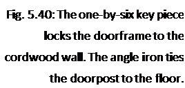
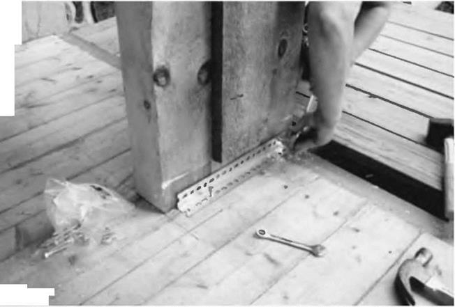
We have an exterior door in the sunroom, and an internal doorway connecting the new room with the dining room in the house. Both are framed to accommodate three-foot-wide (91-centimeter-wide) doors and both are located in 16-inch-wide cordwood walls, one 22 years old and one brand new. In each case, our doorframes consist of double-wide four-by-eight doorposts, with a similar lintel overhead. To join the two four-by-eights together into a single four-by – sixteen doorpost, I installed a vertical one-by-six “key,” as seen in Fig. 5.40. Cordwood walls can be built right up to this key piece, and the log-ends can even touch it in the middle of the wall. Both the inner and outer mortar joints (each 5 inches wide) are laid up right against the doorpost, effectively locking the cordwood panel against the post. We use a similar detail at all post locations. Note also in Fig. 5.40 how a piece of angle iron is used to fasten the doorpost to the wooden deck. The angle iron, like the key piece, will wind up hidden in the cordwood wall.

The window on the west side is installed within a frame made from double­wide two-by-eight cedar planks, planed to 1 Vs inches (4.8 centimeters). The inner and outer components of the frame are scabbed together with a one-by-six (2.5- by-15.2 centimeter) key piece, similar to the one seen in Fig. 5.40. The frame “floats” in the cordwood wall, but is carefully centered. A strong lintel, seen in

Fig. 5.42 below, carries the load of the rafters down onto the cordwood wall.

Подпись: Fig. 5.40: The one-by-six key piece locks the doorframe to the cordwood wall. The angle iron ties the doorpost to the floor.image148Wood finishing. We sanded and varnished the window surrounds, and the posts and girders, but not the five – by-ten rafters. I used my trusty Makita 5"disk sander, #80 grit paper, to finish the timbers, some before construction, and some, as an afterthought, in situ. In retrospect, it would have been easier and more pleasant to do this sanding before installation. A belt sander is another option, but use a dust mask in either case. And listen to Mark Powers, one last time:
My new favorite tool is a Bosch portable 4" planer. It does a wonderful and relatively quick job of finishing the timbers before they’re installed. My posts are sugar maple and the various beams are white ash, maple and beech. Once the grain is exposed, they are absolutely beautiful. I’ve used both a belt sander, and, now, the planer to finish timbers. Hands down, the planer is the way to go, yielding a beautiful almost glassy finish and removing only the bare minimum of wood. Besides revealing the natural beauty of the grain, finishing the timbers eliminates a lot of dust catching in the home.

We sanded the spruce floor and applied three coats of floor oil, which we had used successfully in the main part of the house. Something was different about the wood in the new room, though, and we found that shoes easily marked the oiled floor, and the marks were a real pain to clean. We finally broke down and, over the oil, applied two coats of Gym Seal, a hard clear surface used on gymnasium floors. Now the floor looks great and does not scuff.

The Earth Roof

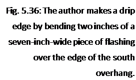
Подпись: Fig. 5.36: The author makes a drip edge by bending two inches of a seven-inch-wide piece of flashing over the edge of the south overhang. image143In the previous chapter, I told of the double-roof system, with false or secondary rafters over the real ones, and insulation as the filling of a plank sandwich. But the new sunroom extends the shallow 1:12 slope of the main house, and we wanted to continue out with the earth roof.
If plank-and-beam is my favorite structural system for roofs, then earth is my favorite roofing material. It is quiet and cool, warm and natural, cheap and beautiful, and ecologically harmonious. Done properly, it is also the longest- lasting roof, because the earth protects the substrate from the three things that break down every other roof surface: ultraviolet solar radiation, freeze-thaw cycling, and erosion.

While I have tried hard not to stray far from the subject of alternative timber framing in this book, I am going to make an exception here and devote a little space to the earth roof, because this information is so hard to find elsewhere, and 1 think earth roofs should be used wherever possible for the reasons given.

The best way to install an earth roof, in my view, is as follows:

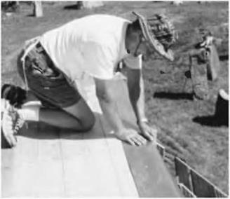
1. Begin with a drip edge all around the building. You can buy ten-foot sections of galvanized metal drip edge for about $4 a section, but I prefer to make my own from seven-inch-wide aluminum flashing, so that I can place a full five inches onto the deck, which makes it easier to apply the membrane, and to keep it from the sun’s UV rays. Fig. 5.36.

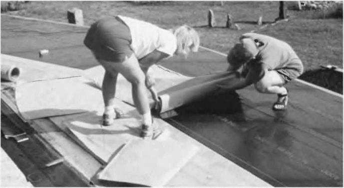
2. Install a good-quality waterproofing over the planking. I like the W. R. Grace Bituthene™ 4000 waterproofing membrane, because it is good quality, moderate in cost, and easy to install. Fig. 5.37.

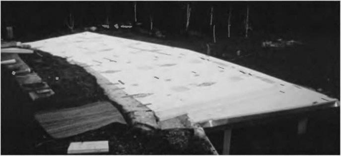
3. Over the membrane, install four to six inches (10.1 to 15.2 centimeters) of extruded polystyrene insulation, rated at about R5 per inch. Fig. 5.38.

4. Over the insulation, place a continuous layer of 6-mil black polyethylene. This cheap black plastic (you can do a 1,000 square-foot, or 93 square – meter, roof for $6o) is the base of the important drainage layer, which takes some burden off of the membrane. My earth-sheltered workshop

Fig. 5.37: Diane Lukaris and Jaki Roy roll out the Bituthene™ 4000 waterproofing membrane onto the wooden substrate, which has already been primed with a compatible acrylic primer provided with the product The backing paper is removed as the 36-inch – wide membrane is rolled out, exposing a very sticky bitumastic membrane that adheres extremely well to the primed wooden deck. The ladies are careful to maintain the required three-inch overlap between adjacent courses.

image144image145Fig. 5.38: We installed 4 inches of Dow Styrofoam™, an extruded polystyrene, over the membrane.
The Earth Roof

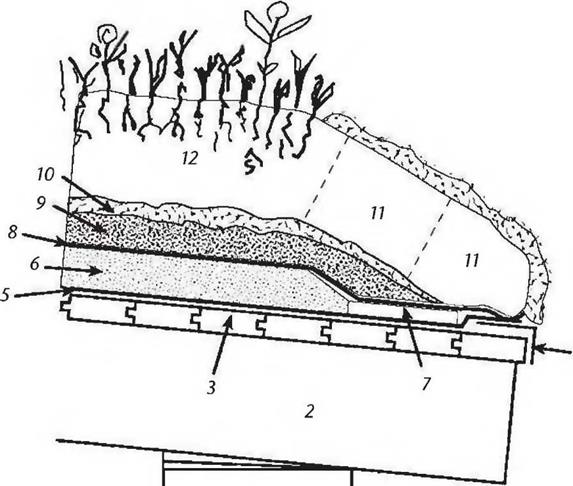
students know that my favorite mantra in this regard is: “Drainage is the better part of waterproofing. Give water an easier place to go than into your house.” Photos are unnecessary for the remainder of the earth roof commentary, but I will draw you a picture of the various roof layers for reference, which is Fig. 5.39. Please refer to the drawing as you follow the text.

5. Install the drainage layer, consisting of two inches (5.1 centimeters) of #2 crushed stone. This is stone about an inch (2.5 centimeters) in diameter.

6. Over the crushed stone, install two to three inches (5.1 to 7.6 centimeters) of loose hay or straw, which will eventually compress and decompose down into a natural filtration mat. It keeps the crushed stone drainage layer free of soil.

Fig. 5.39: Roofing detail for a free­standing earth roof using moss sods to retain the earth.

Key:

1. Above-grade wall.

2. Heavy wooden rafter.

3. 2" x 6” T&C planking.

4. Aluminum flashing as drip edge.

5. W. R. Grace Bituthene™ 4000 or equal membrane.

6. 4" to 5" rigid-foam insulation

7. 1" rigid foam or half-inch fibreboard to protect membrane.

8. 6-mil black polyethylene.

9. 2" of #2 crushed stone drainage layer.

10. Hay or straw filtration mat.

11. Moss or grass sods cut from sandy soil, retain the earth at the edges.

12. Подпись: 4image146Подпись: 1image1477" to 8" topsoil, planted.

7. Over the hay or straw filtration mat, install enough earth to maintain a living roof. In temperate climates with moderate rainfall, eight inches (20.3 centimeters) is enough. Saturated earth weighs 120 pounds per cubic foot (1,922 kilos per cubic meter), so, to keep timber sizes down to something reasonable, we don’t want to put any more earth up there than necessary.

8. Seed with whatever you like — grass, vetch, wildflowers. Mulch and water as necessary until the green cover is well established.

Planking the Roof

We used the same spruce two-by-six tongue-and-groove boards for the roof deck (sunroom ceiling) as we used for the floor. The most difficult part was tearing up a couple of feet of the earth roof on the house, so that we could marry the new roof to the old. I was pleased that the new material — from Russia — was almost identical to the lumber Fd used in the original roof, which was from Quebec. So, once the rafters had been extended, and the old gutter and drip edge removed, Anna and I were able to install the roof deck very quickly indeed, about two days. The work was easier than the floor because 1) we didn’t have to fit the first plank to a cordwood wall, 2) there were only two — large — facets instead of three smaller ones, 3) we were nailing to five-by-eights instead of four-by-tens and 4) we could let all the boards run long and trim the east and west overhangs with one single straight cut. With regard to 4), I let the tongue-and-groove planks overhang eight inches on the east and west walls. More would have been nice, but I was concerned about going too far out with cantilevered planking, considering that the earth roof, soaking wet with snow, can weigh 185 pounds per square foot (903 kilos per square meter).

A. Balance-Beam 0 Secondary Rafters

We had the same deck situation upstairs as downstairs: planking span was starting to get rather extreme about six feet from the main building. But, this time, we could use a simple and rather elegant solution not available downstairs: short secondary rafters. They are, I suppose, a kind of double cantilever, but 1 think the term “balance beam” paints a more accurate picture. Have a peek, again, at the rafter plan, Fig. 3.2 on page 109. The four five-foot-long (1.5-meter-long) secondary rafters are supported at their middle by the eight-inch wide girder, with 26 inches (66 centimeters) extending out as overhang, and the other 26 inches extending in as… “underhang?” Whatever you call it, once the planking and heavy roofing is on, these short rafters are perfectly balanced, and their five – by ten-inch dimensions are stout enough to resist the shear and bending stresses of even a very heavy earth roof.

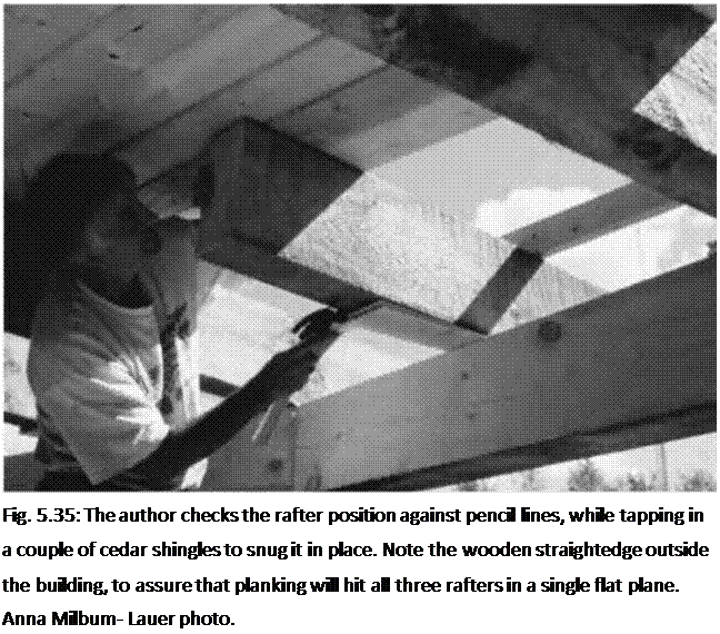
Anna and I installed them in a couple of hours. We’d already prog­ressed with the roof planking beyond the point where the balance beams would go, which helped greatly with their installation. We simply man­handled (and woman-handled) the balance beams up into position, halfway between their longer brothers, and shimmed with shingles until the inner end of the beam was tight against the planking. This can be seen very clearly in Fig. 5.35.

Подпись: Fig. 5.35: The author checks the rafter position against pencil lines, while tapping in a couple of cedar shingles to snug it in place. Note the wooden straightedge outside the building, to assure that planking will hit all three rafters in a single flat plane. Anna Milbum- Lauer photo. When the room was completed,

Jaki “suggested” that I cut a little 45-degree bevel into the rather stark exposed inner right angle of the rafters. I put up a little resistance — circular saw cuts overhead are not my favorite — but her idea is really a great design detail. A picture of this, Fig. 5.44, appears at the end of this chapter.

Installing the Five-by-Ten Rafters

As with the four-by-eight floor joists, we used two different methods of extending the five-by-ten radial roof rafters. The existing rafters, protected by a good overhang, were in excellent condition and extended between 18 and 23 inches (43.7 and 58.4 centimeters) from the cordwood walls. On the east and west rafters (which eventually would have supporting cordwood walls below them), we left the original overhanging rafters as they were, but cut a 2-by-io by 22-inch (5.1-by-

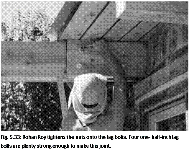
25.4 by 55.9-centimeter) piece out of the new rafters so that they could fit up to the side of the overhanging rafters, as seen in Fig. 5.33. Then we used four one-half – by eight-inch lag bolts to hang the new rafter onto the old. The hex-heads and washers show on the outside. Carriage bolts are an option here.

Подпись: Fig. 5.33: Rohan Roy tightens the nuts onto the lag bolts. Four one- half-inch lag bolts are plenty strong enough to make this joint. Notice, in Fig. 5.33, that the original red pine rafter twisted slightly after construction, as red pine is inclined to do. I was able to straighten the rafter extension by making a biased cut out of the new rafter. This made for a tricky chainsaw cut. The key to success in this sort of thing is to mark the angle correctly on the piece to be cut. And the key to marking it correctly is to double – and triple­check your angles and measurements. As I tend towards a slight dyslexia on this sort of thing, I would explain what I was doing to willing ears such as Rohan’s. He picks up quickly on wooly-minded thinking.
After the framing was completed, and the roof installed, we covered this rather unattractive join with cordwood masonry. The outside looks great, as if it’s a single rafter originating from the center of the house. On the inside, no rafter is in evidence, as it is hidden behind short log-ends.

The other three rafter extensions would be exposed in the room, so appearance was important. I designed a rafter plate which could be made from standard one-quarter – by 8-inch (.63- by 20.3-centimeter) steel stock. A twelve – foot section of this material was cut at the local Steel Service Center into six 24- inch (61 centimeter) pieces. I made a hole-drilling pattern out of a piece of plywood, and my friend Bruce Kilgore kindly drilled all the one-half-inch holes for me with his drill press. Before installation, Anna Milburn-Lauer painted all six pieces with two coats of spray-on flat black enamel.

As already stated, truss plates must be used on both sides of the joint for strength. Now, you may be tempted to try to fasten both plates to the rafter by the use of six-inch lag bolts, but leave that temptation behind. The chances of the holes of both plates lining up with holes drilled through the rafter are slim to nil. I saw

an architect-designed detail like this on a job once, where eight-by-eight posts were supposed to be installed into pre­drilled heavy metal U-shaped post holders, already fastened to the foundation. The architect wanted bolts all the way through, but the contractors couldn’t hit the hole in the plate on the other side, even with their long bits. Lag screws from each side, however, are plenty strong, and that’s what we chose.

Подпись: • 4Подпись: *Подпись: Fig. 5.34: Anno tightens log screws up ogoinst the metol plote, which acts as its own washer. Rohan drills three-eights-inch holes for the plate on the other side, appropriate for one-half-inch lag screws. He hangs the plate in position on two small screws, which hold it in place while he drills his holes.image141Each plate would require eight half-inch by з^-іпсії (1.2- by 9.0- centimeter) hex-headed lag screws. Six times eight is 48. It was quite a bit cheaper to buy two boxes with 25 screws per box than to buy 48 pieces out of the bin. So I have two left over.
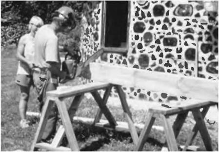
The new rafter was butted up to the old rafter, with its south end supported by the new girder system, just installed. We jammed a two-by-four under the north end of the new rafter to hold it firmly against the end of the overhanging old rafter. Rohan and Anna installed the plates, as seen in Fig. 5.34.

Raising Heavy Timbers

Traditional timber framers will make all their bents ahead of time, and have them stacked in the proper order, waiting for the big day when plenty of help is gathered together for the raising. Lots of bodies wielding poles, as seen in Fig. 2.17, lift the bent to vertical. The poles can also act as temporary stops to aid during the lifting process. Someone — usually the boss — checks the bent for plumb, as diagonal bracing is fastened.

Oftentimes, professional timber framing contractors hire a crane for the big day.

My experience over thirty years has been to raise posts individually, brace them with temporary diagonal supports, and then to raise the girts or girders one at a time. Usually, this involves just two to four people, as at the Earthwood addition, but, in the case of a 30-foot ten – by-ten at Log End Cave, eight people and a pick-up truck were involved in the installation.

Mark Powers, now building a Log End Cave type of home with very heavy rafters, and working mostly alone, says: "With some creative engineering, I’ve been able to raise all of my girders and rafters with my trusty Kubota 45-horsepower tractor with its quick-attach forks and bucket. I can’t imagine building the house without it."

At Earthwood, I had fun raising a fairly green 15-foot ten-by-twelve oak girder — probably over 700 pounds (318 kilos) in weight — to the top of the posts, aided by just one other helper. We accomplished the feat by raising an end of the timber with a lever, and slipping a concrete block under it, about 40 percent of the way along its length. Now lifting the other end was easy, as the overhanging 40 percent of the beam’s weight cancelled out another 40 percent of the weight at the lifting end. Again, we made a slightly higher block stack 40 percent of the way in from the new lifting end. We alternated our lifts back and forth, end to end, always adding a block or two to the low stack. After a couple of lifts, we rebuilt the block stack with criss-crossed block construction, for greater safety and stability. In short order, we had the beam up to height, and then, one end at a time, transferred its load onto the braced posts.

to structural — problem, and it could easily have been avoided. But as I have said before, heavy timber framing is forgiving, particularly if you are willing to forgive yourself once in a while.

There Are All Kinds of Ways to Cut a Beam

There Are All Kinds of Ways to Cut a Beam

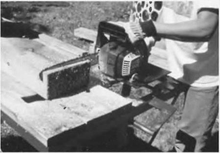
Chainsaw

image132

Fig. 5.25: Chainsaw. The author cuts a heavy timber supported at a convenient height by sawhorses. The saw cut can be no better than:

1. The accuracy with which the pencil marks are trans­posed to the timber. Use a good carpenter’s square and mark all around the timber, to make sure that — after its circumnavigation — the mark returns to the point of beginning. If it doesn’t, the cut cannot be square. Always set your square on the beam being cut, not on the piece being cut off.

2. The quality of the chain and bar. The right – and left-side chain teeth must be sharpened equally to prevent pull to either direction, and the bar must be straight, with a clean, un-nicked groove.

3. The skill of the operator. In this regard, I can only say: Practice, practice, practice! Always cut on the long side of the line. A chainsaw removes about a quarter inch of wood. This is called the kerf. Don’t make your post a quarter inch short!

Note the use of a chainsaw safety helmet for sound and kickback protection, as well as to keep wood chips out of your eyes. Use protective leg chaps in case the saw cuts through the timber and continues on to your knees and legs.

Cutoff saw

image133

Fig. 5.26 Cutoff saw. This cutoff saw moves the chain through a vertical arc, perpendicular to the timber on the table. This advantage makes it easier to maintain a consistently straight cut.

There are also 24-inch circular saws made for crosscutting, also called beam cutters or compound miter saws. Log cabin builders and professional timber framers use these all the time. Contractor Russell Pray owns one of these and used it to make perfect right- angle cuts on the posts and beams at the Earthwood garage. They are very expensive, though, and it would make more economic sense to hire one for a day from a contractor’s tool rental store rather than buy one.

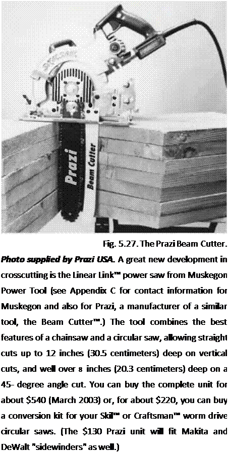
Подпись: The following option is much more affordable.Подпись: Crosscut saw attachment for a circular sawПодпись: Fig. 5.27. The Prazi Beam Cutter. Photo supplied by Prazi USA. A great new development in crosscutting is the Linear Link™ power saw from Muskegon Power Tool (see Appendix C for contact information for Muskegon and also for Prazi, a manufacturer of a similar tool, the Beam Cutter™.) The tool combines the best features of a chainsaw and a circular saw, allowing straight cuts up to 12 inches (30.5 centimeters) deep on vertical cuts, and well over 8 inches (20.3 centimeters) deep on a 45- degree angle cut. You can buy the complete unit for about $540 (March 2003) or, for about $220, you can buy a conversion kit for your Skil™ or Craftsman™ worm drive circular saws. (The $130 Prazi unit will fit Makita and DeWalt "sidewinders" as well.) This sturdy chain kit can replace your circular saw blade in a few minutes, and enables you to make deep accurate crosscuts through beams up to a foot thick. Think of the accuracy and convenience of a circular saw, combined with the depth of a chainsaw. It can even be used to do minor "saw milling," if you need to rip an inch or two off the edge of a beam. (For major saw milling, use one of the chainsaw mills described in Chapter 3.)
Circular saw and handsaw

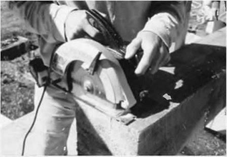
image135

Fig. 5.28: Circular saw and handsaw. After marking the square cut all the way around with a pencil and square, use a circular saw to cut as deeply as possible into all four surfaces, all the way around the beam and back to the original side. My seven-inch (17.8- centimeter) circular saw will allow me to make a vertical cut 2-1/2 inches (6.3 centimeters) deep, maximum. With an eight-by-eight, cutting into all four surfaces will leave a square of uncut wood in the center about three inches (7.6 centimeters) square, which you can finish with a good sharp handsaw. The cuts made with the circular saw will guide your handsaw straight through.

When you think you’ve got a good square base on your post, try it at its actual location to see if it stands up vertically. If it is good, measure (twice!) and make the square cut at the top end. Don’t be nervous — timber framing for the rest of us is quite forgiving, unless you happen to be a card-carry­ing obsessive-compulsive neat freak. Tapered cedar shingles will tighten up any joint, and can often be hidden, or at least sanded smooth and rendered almost invisible.

Once the post is the right length, stand it in place. Fastening to concrete foundations was discussed in Chapter

4. In our sunroom, we were standing the post onto a wooden substrate, the two-by-six tongue-and-groove floor.

In Fig. 5.29 Jaki and Anna plumb a post. We felt we had a good square cut on this one, yet it still wanted to lean in slightly. Anna tapped in the thin edge of an eight-inch-wide cedar shingle, while Jaki consulted the plumb bubble of her four-foot level. In Fig. 5.30,1 toe – screw the post in place, a couple of screws each side. Right angle connectors are another option here.

Because of the odd angles where girders meet on the south wall (please revisit Fig. 5.2), two of the posts required some custom work at the sawmill. I used my angle square to capture this angle, and transposed it to the ends of a couple of six- by-eight posts, already made. I took the timbers back to the sawmill and showed Norm, the sawyer, how the post needed to be ripped on the bias so that, when placed up against its neighbor, the resulting “double-wide” post makes the slight angle turn in the wall. Norm loves this sort of challenge, and clamped the piece onto his movable carriage with shims to create the angle. In no time, I had the
required posts with their trapezoidal

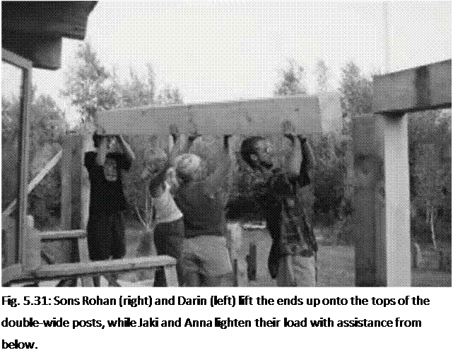
Подпись: Fig. 5.31: Sons Rohan (right) and Darin (left) lift the ends up onto the tops of the double-wide posts, while Jaki and Anna lighten their load with assistance from below. cross-sections.

Installing the Girders

The posts are all installed — and braced — and the girders have had their angles cut as described above (see Preparing the Girders, pages 121—122).

Now it is time to blow the whistle on some muscle and heft the girders into place. We had enough help right in the family so that I could hide behind the camera. By the way, I think of these beams as girders, because they support

rafters, but, as they are on the edge of a building, they can also be called girts.

We started with the west girder, letting the west end run long. Its overhang could be cut to length later in situ. We did not fasten it yet, for its own weight kept it in place. The second one — the central girder — was the really heavy one: a ten-foot six-inch full-sized eight-by-ten of fairly green white pine. But many hands make light work. See Fig. 5.31.

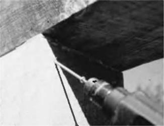
Подпись: Fig. 5.32: A couple of screws hold the girder in place. Right-angle connectors are good in this situation, too.image139After all three girders were set in place, we adjusted their positions slightly with a heavy hammer, sliding them this way and that until we were happy with the way they sat and joined each other. Small wooden shingle shims can be used as necessary to take any wobbles out. Then I toe-screwed up through the posts into the underside of the girders, using two screws at each side of a post. Fig. 5.32. I made a mistake at this point that you can avoid. I should have fastened the top sides of the girders together with truss plates, as I had done many times before. I either forgot to do this, or felt it wasn’t necessary, or thought that the truss plates might get in the way of rafters later on; I really don’t remember. (And excuses are like belly buttons; everybody has one.)

But the girders did separate by about a quarter inch (6.3 millimeters) later on. This is a cosmetic — as opposed