Category Timber Framing for the Rest of Us Rob Roy

Some More About Doorframes and Posts

With a lot of natural building being done these days, cordwood, cob, or straw bale walls of 16 to 24 inches thick are not uncommon. Doorframes will have to be equally wide. Earth woods cordwood walls are all 16 inches (40.6 centimeters) thick, so I make my doorframes from two four-by-eight timbers, with their 4-inch
(ioi millimeter) dimensions butted together, forming, effectively, a 4-by-i6-inch door post. These vertical timbers can be fastened together with metal straps, as shown in Fig. 4.54.

Fastening such a doorframe to a concrete floor requires two pins, one for each of the four-by-eights, to stop the doorframe from rotating. Alternatively, a 12- to 16-inch-long piece of angle iron can fasten the frame to the floor as discussed above, and the angle iron is hidden from view in the cordwood wall.

With single posts, such as eight-by-eights, two pins instead of one will stop the post from rotating, and I have mentioned this to students for years. In point of fact, we only used one pin for each of the posts at both Log End Cave and Earthwood, and I have seen no sign of any post rotating. The heavy concentrated load on these posts imparts tremendous friction at each post end, and rotation would be highly unlikely, especially after girders and floors above the posts tie everything together. One pin is enough with heavy structures.

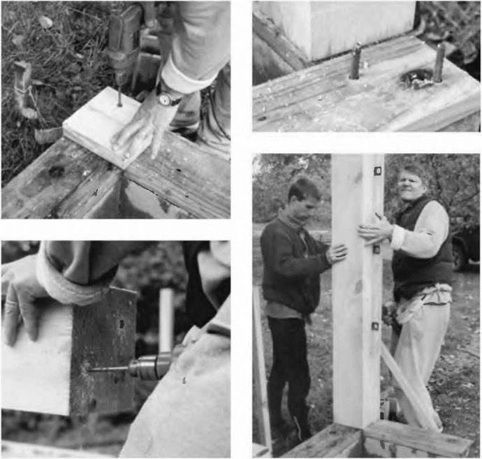
Chris Ryan, like any good builder, likes to use patterns to make jobs easier. My son Rohan helped him set up a corner post at his garage while I took the following sequence of photos:

Fig. 4.8: Chris made a pattern from an eight inch piece of two-by-eight, held it firmly on the corner of his garage footing, and drilled two holes straight down into the plate, already fastened to a course of blocks as described above.

Fig – 4-9: Next, Chris installed a couple of positioning pins into the two-by – eight pressure-treated plate. The pins are made from scrap half-inch (1.2 centimeter) #4 reinforcing bar, or “rebar.”

Fig. 4.10: Chris used the pattern to transpose the pin locations to the underside of his eight-by-eight corner posts. In this photo, Chris completes the holes, deep enough so that the post will sit firmly on the sill plate. Rohan and Chris will put the heavy eight-by-eight post in place over the pins seen in Fig. 4.9.

Fig. 4.11: Here, Rohan adjusts the post while Chris checks the plumb bubble of his four-foot level. When the post is plumb, he screws the short brace diagonal into place. The post is plumbed and braced in both directions. One down, about 15 more to go (including four-by-eight doorframe posts.)

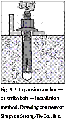
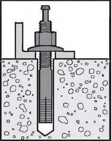
image44image45Подпись: Fig. 4.7: Expansion anchor — or strike bolt — installation method. Drawing courtesy of Simpson Strong-Tie Co., Inc. In areas of high winds, positioning pins alone may not satisfy local code, and you will probably have to use a code-approved metal fastener for the purpose. But, before we look at these, we should discuss metal fasteners and connectors in a general way.

image47

Sill Plates and Sill Beams

Very often, a two-inch thick sill plate is fastened to the foundation, and the wooden frame is attached to that. This sill plate is usually bolted to the foundation all around its perimeter. Yet another neighbor, Chris Ryan — we live in a community of owner-builders — did this at his new garage. First, he laid a course of ordinary eight-inch concrete blocks around the perimeter of his slab, except where his doors would be, because he wanted to keep his posts (and his cordwood masonry) about eight inches (20 centimeters) off the slab. (Fig. 4.3 is actually a detail from the Ryan garage.) Then, at appropriate locations, he filled block cores with concrete and placed anchor bolts into the fresh mix. (Use any bagged dry concrete mix for this, such as Sakrete® or equivalent.) Anchor bolts are in the shape of a long upper-case letter L, and come in various sizes, but a typical one for this purpose would be eight inches long and one-half-inch in diameter, with the top few inches threaded to receive hex-headed nuts. Chris left the bolts sticking out about 1У2 inches (3.8 centimeters) proud of the top of the blocks.

For an eight – or ten-foot sill plate, place an anchor bolt such that there will be one about six inches (152 millimeters) in from each end, and one in the middle of the planks length. Although PT material will not deteriorate in this application, it is still a good ideal to install a roll of Sill Seal® or equivalent. Sill Seal is a blue foam that comes in a roll, eight inches wide and about one-quarter-inch thick. It will help resist rising damp and will also seal against drafts coming in where the sill plate meets the foundation.

Set the plates on top of the anchor bolts and hit the plate with a hammer at each bolt location to make a mark. Drill a five-eighths-inch (1.6 centimeter) hole through the plate at each mark, and install the plate using flat washers and half­inch nuts. Chris countersunk the holes in the plate to accommodate the washers and nuts, but with most infillings, a nut and bolt assembly protruding a half inch proud of the plate will not present a problem.

On a poured footing or slab, you may wish to place the anchor bolts right in the fresh concrete, but be sure to get them in useful positions. If you do make an error, you can always hacksaw any errant bolts off, and install pins by the expansion shield or strike bolt methods already described.

With traditional timber framing, the sill might be a heavy timber, such as an eight-by-eight or better. Timber framer Steve Chappell tells me that these heavy sills are normally installed first, and the bents are raised up on them, with the mortises and tenons all ready to join each other at the time of raising. Where wind uplift is not a code issue, Steve simply pins these heavy timbers to the foundation. He uses metal foundation straps where required by code. You can jump ahead to Fig. 4.54 to see these straps used in an area prone to earthquakes. Steve feels strongly, as I do, that heavy timber frames have a powerful natural resistance against wind uplift.

Most of “the rest of us” place posts directly down on the foundation (not forgetting the damp-proof course) or use a two-by sill plate, like Chris did at his garage. However, at Log End Cottage, our first timber frame structure, built in 1975, we used heavy ten-by-ten (25.4 by 25.4 centimeter) barn beam sills at the gable ends and full-sized three-by-ten sills along the longer sidewalls. The three – by-tens were fastened to the top of the block wall by the method described for Chris’s garage. With the ten-by-tens, we simply set anchor bolts sticking out two inches, made an impression on the underside of the sill with a good strike of the hammer, drilled the receiving holes, and placed the sill beams onto the foundation over the 1970s equivalent of Sill Seal. This stopped the sill from moving laterally. There is no way that this heavy sill and building is going to leap upward off of the positioning pins.

If code requires that you anchor such heavy timbers down, you will need to use threaded rod set in grouted block cores or into the poured concrete footings. The rod would have to extend eleven inches (28.0 centimeters) for a ten-by-ten (or ten inches if you want to countersink the washer and nut.) Alternatively, you may be able to fasten the girder by other strap fasteners set in the concrete for the purpose — see Joe Zinni’s case study at the end of the chapter — or you might choose the angle iron method, described next.

The angle iron method can be very useful where a doorframe is installed after the rest of the frame is already built. However, you can use the technique in all sorts of applications, so I will spend a little time on it now.

Any good building supply will have galvanized angle iron of various sizes and gauges. Four-foot-long sections are a common item, and they are usually stocked near the truss plates and joist hangers. These inexpensive pieces have a number of round or oval holes on both faces of the angle iron, giving almost infinite flexibility for installing lag screws pretty much anywhere you like. You can cut the angle iron quickly with a hacksaw into useful lengths: eight inches, twelve inches, or whatever.

Подпись: Fig. 4.6: Leaded expansion-shield installation method. Drawing courtesy of Simpson Strong-Tie Co.r Inc. It goes like this: Set the doorframe (or post or sill beam) on the slab, floor, footing or sill. Using a pencil, mark the doorframe’s location on whatever surface you are going to fasten to. Choose a length of angle iron a little shorter than the width of the piece you wish to fasten, set it against the pencil line, and choose a couple of appropriate hole locations. Scribe these with a pencil, using the little piece of angle iron as a template. If the receiving surface is concrete, drill appropriately sized holes for whatever anchor you have chosen (leaded expansion shields with lag screw method or strike bolt method). Fasten the angle iron as shown in Figs. 4.6 or 4.7. If you are fastening to a wooden deck, as in Fig. 5.40 on page 136, just drill the appropriate hole into the wood for the lag screw selected.

Now, set the wooden member up next to the angle iron and, with a pencil, scribe a couple of appropriate hole locations on the post, doorframe, or heavy sill. Drill holes into the wooden member, using the correct diameter and depth for the lag screws chosen. Quarter-inch or flve-sixteenths-inch screws of two to three inches in length are appropriate. I make my holes in the wood about a quarter – inch less than the full length of the screw below the hex head, and I use a drill of about the same size as the solid shaft (not including threads) of the lag screw. When in doubt, use a smaller size. If this is too tight, you can always make the hole a little bigger. If the screw is too loose and doesn’t hold, you will have to drill again nearby, using a smaller hole.

With any lag screwing that you do, it is always wise to test the drill hole size and the screw itself on a piece of similar-species scrap wood. You want a fit that is snug and tight, but not so tight that the wood splits or that it is impossible to turn the screw.

Finally, set the wooden member up again and install the lag screws through the angle iron into the receiving hole in the wood. Snug the screws up with a hex – head ratchet wrench. I particularly like this method when I am unable to lift a post or doorframe over an anchor pin, such as when placing a new member within an existing post-and-beam panel.

Fastening the Timber Frame to the Foundation

Whatever foundation method is selected, local codes will vary on their requirements for tying the timber frame down to it, depending on the likelihood of hurricanes, tornadoes and earthquakes. In most areas, a heavy timber frame will not vertically leap off of the foundation so the main consideration is to prevent the sill plate or the posts from moving laterally. This is most easily accomplished by joining the posts to the foundation with positioning pins. As northern New York does not suffer from any of the aforementioned natural disasters, this is what I have been doing with all our buildings since 1975.

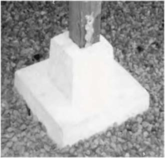
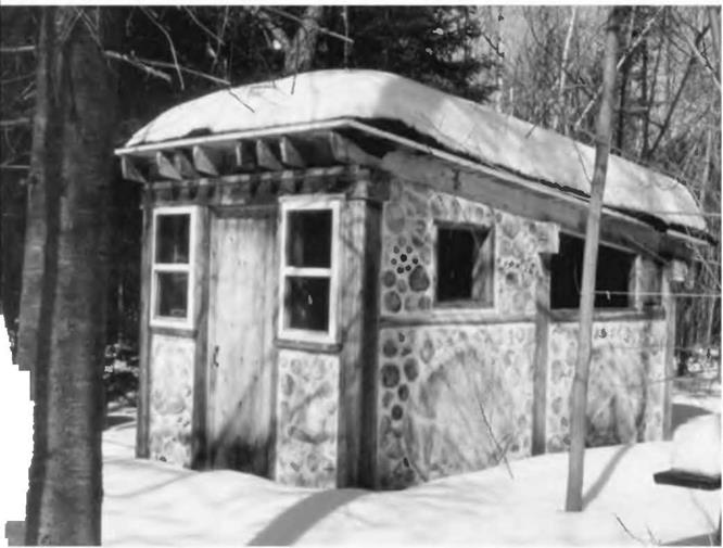
The joint between posts and foundation. Sometimes just the posts are fastened to the foundation, and infilling (such as cob, cordwood, or straw bale) completes the wall between posts after the frame is completed, such as La Casita in Fig. 4.2. Our downstairs doorposts at Earthwood are also pinned direcdy to the foundation. I pour the footings or the floating slab without placing positioning pins (anchor bolts) in the concrete, for two reasons: 1) It is difficult to trowel the concrete smoothly within a few inches of the anchor bolt, leaving an irregular bearing surface for the post to stand upon and 2) Murphys Law tells you that the pin or anchor bolt will not be in the right place when you come to use it, particularly with doorframes.

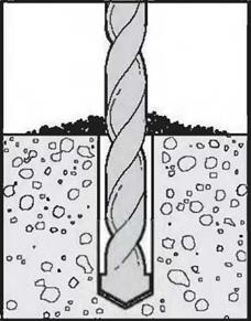
Therefore, I install my positioning pins in another way. After the concrete has set — it is hard and strong after two weeks — I use a carbide masonry bit to drill holes into the concrete exactly where they should be. I can measure off the corners and double-check my measurements. These holes are drilled the same depth as the length of the expansion shield which will be later driven into them. These cylindrical shields, available at any building supply store, are made of lead and are split in half to receive a certain size lag screw. The shield has all the pertinent information molded right into the lead. For example, you might see D, %S’’embossed in the lead. This tells you to drill the hole with a five-eighths-inch (1.6 centimeter) Drill bit, and that you will insert a three-eighths-inch (1.0 centimeter) screw into the shield later. Drill the hole a smidgen deeper than the length of the shield. I find two-inch (5.0 centimeter) shields to be convenient: not too much drilling, but plenty strong enough. Blow the dust out of the hole with a straw, but wear eye and nose protection.

The shields are driven into the clean hole with a hammer so that the top of the shield is flush with the concrete surface. Next, turn the hex-headed lag screw into the shield with a socket wrench until the screw is tight. Choose a length so that when the hex head is cut off (takes 30 seconds with a hacksaw), about two inches will be left exposed above the concrete. If you use a two-inch shield, then, you will want to buy four-inch lag screws.

There is another fastener that will do this job a little more easily and has the advantage of leaving a threaded end proud of the foundation, for the installation of angle iron as a fastening aid or for the installation of sill plates (described below.) Simpsons fastener of this kind is called an “Easy-Set pin drive expansion anchor,” quite a mouthful, so just ask the clerk for an expansion anchor or strike bolt. A pin sticks out of the anchor, and when the pin is struck, the anchor expands tightly into the hole. So, again, drill a hole (Simpson recommends a hole one-sixteenths-inch greater than the anchor diameter), insert the anchor, and give the pin a good blow with a hammer. Choose a length of strike bolt appropriate for the application. For most purposes, leave the top of the anchors shaft extending two inches proud of the foundation. The downside of strike bolts is that they are about three times as expensive as the expansion shield method, so I still use the shields and lag screws. They don’t call me Rob Roy for nothing.

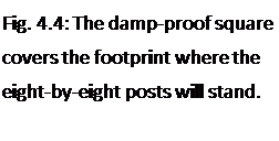
Now, before installing the post, there is a very important step which must not be omitted. Cut a square of material — called, by the Brits, a “damp-proof course”— the same size as the footprint of the post. An eight-by-eight post requires an eight-inch by eight-inch (20 by 20 centimeter) square of damp-proof material. I have used pieces of asphalt shingle as well as 240-pound roll roofing for the purpose, both successfully. These materials are almost an eighth of an inch thick. Before placing the posts, position the square of asphalt over the anchor pin and press down. Sometimes you can actually press the square down over the pin right to the foundation. Sometimes, you may have to make an impression and actually cut the little hole out with a knife. In either case, you will now have the post’s footprint completely covered to prevent “rising damp.” This protects the underside of the post from deterioration by damp and rot. Believe me, it works. I have done this for 25 years with no deterioration in any post or doorframe. (The International Residential Code at Section R323 also requires “an impervious moisture barrier,” wherever a wooden post meets concrete.) I have seen others put the post directly on the concrete without the square of asphalt damp proofing, and those posts have deteriorated badly. Plus, the almost eighth-inch thick piece
acts as a steadying or leveling influence when it comes to actually standing the post in place.

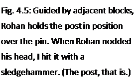
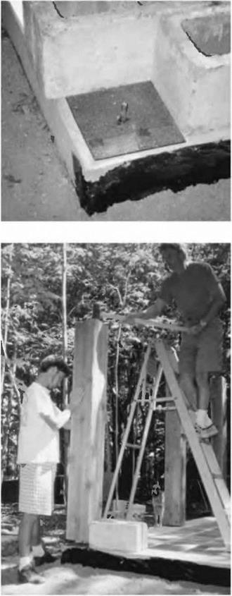
Подпись: Fig. 4.5: Guided by adjacent blocks, Rohan holds the post in position over the pin. When Rohan nodded his head, I hit it with a sledgehammer. (The post, that is.)image42Подпись:Erecting an individual post is a two-person, two-step process, because of the positioning pin. First, the post is stood up onto the pin. Concrete blocks can be used as positioning aids so that you know that the post will stand on just the right footprints, as seen in Figs. 4.4 and 4.5. Make sure that the post is the right length and has two good squared ends. Now, while one person holds the post, the other person, on a stepladder, gives it one stiff “thwack” with a heavy hammer, making an imprint on the underside of the post. Next, the post is taken down and a hole of the same diameter as the threaded lag screw is drilled at least as deep as the pin is high, say two inches in our example. Finally, the post is stood up again, but this time it is there to stay, the pin in the hole keeping it in the right place, even during an earthquake.

By the one-post-at-a-time method, each post must be supported in two different directions by long diagonal scrap timbers, nailed to wooden stakes pounded firmly into the ground. (If the post is in the middle of a slab, or at some intermediate point along the wall, horizontal pieces of flat scrap, such as two-foot long (61 centimeter) pieces of two-by-four, can be screwed to the bottom of the post to act as stabilizers. A piece of plywood in the shape of an isosceles triangle will work nicely, too. Review figure 2.21).

Post Height

Post height should be figured at the planning stage and your plans should include an elevation view of each side of the house, including any gables. This view will show the posts, the heavy timber girt above them (also called the girding beam) and floor joists, if supported from below by the girt. (The alternative is to hang the floor joists on the girt with metal joist hangers made for the purpose.)

If you are building your own house, chances are that you will be designing it yourself as well. Post height can be figured by working back from the desired ceiling height. For example, let’s say that the plan calls for the ceiling joists to hang from the girts with joist hangers, and, further, that the joists are the same depth as the girts, perhaps ten inches. If you want to maintain eight feet to the underside of the ceiling (or exposed floor joists), then the posts will be the same height as the ceiling or underside of exposed joists. If the joists are installed directly above the girts, then you can shorten the posts by the thickness of the girt and still maintain the desired headroom. With an eight-inch thick girt, for example, a seven-foot four-inch post will still give eight feet of headroom to the underside of the joists.

Another way I have figured this, at four different houses now, is to base everything on the doorframe. Let’s say we start with a standard six-foot eight-inch (203 centimeter) door and use an eight-inch-thick girt as the top part of the doorframe. (Six-foot eight inches plus eight inches equals seven-foot four inches, or 224 centimeters.) Further, let’s say that we support the ceiling joists on top of the girt, not with joist hangers. In this example, headroom clearance will be seven foot four inches to the underside of the joists. With exposed eight-inch joists, the visual effect is eight feet (244 centimeters) to the ceiling planks, quite sufficient unless you are very tall. This is the way it is downstairs at Earthwood as well as in the new solar room upstairs (see next chapter) and we like it. The main upstairs area slopes up from about eight feet at the edges to about nine feet at the center.

All of this is a matter of individual taste, but have such details well planned before you order materials.

Building Techniques: Timber Framing for the Rest of Us

T

O THIS POINT, WE HAVE SPOKEN OF CONSIDERATIONS APPROPRIATE for all timber framing projects. But now we have reached a juncture where traditional timber framers go one way and the rest of us take another path. As Yogi Berra said at a college commencement speech, “When you get to that fork in the road take it.” I say, “Let’s start at the bottom and work up.”

Foundation Options

Timber framing can be married quite happily to a variety of foundation methods, which, in general, can be characterized under four separate categories: piers, footings, masonry walls, and slab-on-grade.

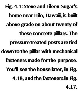
I. Piers. Piers can also be called pillars, columns or posts, and can be made of wood (such as 75-year ground contact six-by-six timbers or railway ties) or of poured concrete. Concrete piers can be in the form of truncated pyramids, such as my friend Steve Sugar did near Hilo, Hawaii (Fig. 4.1 on page 62 and Fig. 4.18 on page 77) or they can be poured within heavy cardboard tubes called Sona tubes. Whether the piers are wood or concrete, they should extend down to below the code-specified frost line where you are building. In northern New York, this is considered to be four feet. It is also a good idea to distribute the load of the post or pier on a large flat stone, say 12 to 16 inches (30.5 to 40.6 centimeters) square. The top of the pillar should be six to twelve inches (15.2 to 30.5 centimeters) clear of grade to protect any wooden post above it, or the sill plate, from damp. Reinforced concrete columns made with Sona tubes can extend three or four feet above grade, if you want to make use of the crawl space under the building.

Подпись:image39While I have nothing against piers made with Sona tubes, my personal view is that the 75-year pressure-treated piers will probably last just as long, are cheaper and easier to install by the inexperienced owner-builder, and if it comes to it, easier to replace.

Подпись: Fig. 4.2: La Casita, a small guesthouse at Earthwood, has its simple post and beam frame founded on a "floating ring beam." See also Fig. 2.21.image40Подпись: 3. Masonry walls. Supported by either footings or the slab-on-grade, masonry walls can be poured concrete, block or even stone masonry. These walls can be of the desired height according to the house style (basement, crawl space, etc.) and should be at least as wide as the post and beam frame

ion today, the footings are installed sheltered space is desired below grade, us to:

2. Footings. Generally made of poured concrete, footings might typically be 12 to 16 inches wide and at least 8 inches (203 millimeters) thick.

With small buildings, such as a sauna or our little guest­houses, I “float” the footings on a good pad of percolating material. See slab-on-grade below. I call this foundation a “floating ring beam” and its construction is detailed in both my books Complete Book of Cordwood Masonry House­building and The Sauna (see Bibliography). (Fig. 4.2.)

With most northern construct – below frost line, whether an earth – or simply a “crawl space.” This leads

and any intended infilling. For example, if the builder wants a 16-inch-wide cordwood wall, built within a strong post-and – beam frame, the supporting wall (and footings) should also be 16 inches wide. (Fig. 4.3.)

Подпись: Fig. 4.3: Here, the posts — and the cordwood wails — are built up on a pressure-treated wooden plate one course of blocks higher than the floating slab.image414. Slab-on-grade. This is also known as the “floating slab” or the “Alaskan slab.” It works on the sound principal that frost heaving is caused by water freezing and expanding below the building. The two approaches taken to avoid this problem are (1) to go down below maximum frost depth with the footings or (2) to prevent water from collecting under the foundation in the first place. The second approach is the way the slab-on-grade works. The poured concrete slab “floats” on a pad of percolating material such as coarse sand, gravel, or crushed stone. The pad drains any water to a place further down grade. There is no water under the foundation to freeze, so no nasty uplifting expansion (called “heaving”) takes place. Again, see Complete Book of Cordwood Masonry Housebuilding for a thorough discussion. But, be sure to follow local code, too. The slab-on-grade does appear in the new International Building Code, now used in most states.

Incidentally, Frank Lloyd Wright liked both the floating slab and another foundation method, which works on a similar principle, called the rubble trench. By this method, a trench is dug down to just below frost level, and then filled with fairly coarse (potato-sized) stone. Footings are formed and poured on this stone at grade level. The trench is drained to some point down grade, so the method is best suited for a site with sufficient grade differential.

The best discussion of the rubble trench foundation, good enough to build from, appears in the excellent book Foundations and Concrete Work (see Bibliography). Using just the information in that book, Ki Light made his rubble trench foundation. A concrete footing floats on the packed rubble, and his post and beam frame (and his straw bales) are founded on this footing. You’ve already seen Ki’s house in Fig. 1.2.

The present book, though, is about timber framing, not foundation methods. Maybe someday I’ll do a book called Foundations for the Rest of Us, but don’t hold your breath. Almost any good generalized building book (including Foundations and Concrete Work, page 17) will show you how to set up “batter boards” to establish a square foundation. This fine inexpensive book also explains the slab – on-grade and other foundation methods.

Seasoning the Timbers

How long to air-dry or season the timbers before use is a much-debated question. The best answer I have encountered is from contemporary timber framer and colleague Steve Chappell in his book A Timber Framers Workshop, listed in the Bibliography. Steve uses the term “curing” to describe the early stages of the seasoning process. He describes this initial phase:

Once the tree dies and is milled, the wood fibers begin to relax and take on their natural shape. There is usually an immediate reaction to being milled in the form of crowning, warping, or twisting, resulting from the inherent tension in the wood, but no shrinkage will occur until all of the free water (moisture in the cell cavities), and the bound water (moisture in the cell walls) begins to leave. (Chappell, 1998, p. 139)

Chappell says that 90 percent of these deformations due to natural stresses being relaxed will take place in the first six months, but adds that “the first eight to twelve weeks is the most rapid curing stage” and that “it is during these early stages that the most dramatic changes will take place.” (Chappell, pp. 139-140) My own experience with the new heavy timbers we used for our new Earthwood addition (Chapter 5) bears this out. I paid a little more for early delivery of the timbers, and the heaviest ones managed to get ten to twelve weeks of excellent drying conditions, a big plus. The white pine timbers were lighter to handle, kept their straightness, and shrunk only marginally on their breadth and width.

I used to think — I suppose I read it somewhere — that the old-time timber merchants would store wood for years to supply builders with dry timbers. Chappell says otherwise, that builders were “more concerned with properly curing their timbers and allowing them to season for as long as was practicable.” Emphasis mine.

To minimize twisting and other seasoning defects, get your timbers home from the sawmill as soon as possible after they are cut, and stack them in good parallel courses, with one-inch wooden stickers between the courses. Choose a flat, well-drained site without vegetation. (Mow the grass as needed.) If the timbers are already showing signs of mold when you get them to your site, you should lay them out individually in the sun for a few days to kill the fungus.

Wood rot, incidentally, is caused by fungi, which use the cellulose in wood as a food. But fungi also need a constant damp condition. If moisture content in wood is below about 18 percent, the fungi will not flourish, although the spores might remain alive, just waiting for more favorable times. This is why proper stacking of wood is so dependent on good ventilation, which is an excellent preventative to rot. This is also why exposed beams in a building are so resistant to fungi and rot: they enjoy superb ventilation. But back to the stacking.

Have a good quantity of dry stickers, which are lengths of regularly – dimensioned scrap wood, to place laterally between courses. They should be at least an inch thick to prevent mold, and at least three stickers should be used per course of wood with timbers up to ten feet long, and four or more with longer timbers. Each course in the stack should be made with timbers of the same vertical dimension. A tall stack is preferable to a wide stack, because the extra weight of the wood acts as a clamp to help minimize any twisting of the wood during the curing process. And put the timbers that you are going to use first on the top of the pile, not the bottom!

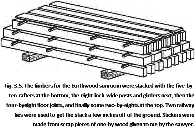
Подпись: Fig. 3.5: The timbers for the Eorthwood sunroom were stacked with the five-by-ten rafters at the bottom, the eight-inch-wide posts and girders next, then the four-byeight floor joists, and finally some two-by-eights at the top. Two railway ties were used to get the stack a few inches off of the ground. Stickers were made from scrap pieces of one-by wood given to me by the sawyer. “Sticker burn” or discoloration can occur where the stickers are placed. If you care about this, get a friend to help you restack the pile, top to bottom, twice during the curing, which, again, puts the first needed timbers on top. Move the stickers a few inches so as not to exacerbate the sticker burn. If you are planning on sanding all the timbers anyway, sticker burn is of less consequence.

I conclude this chapter with a picture of the way I stacked my timbers for our Earthwood sunroom project.

Comparing Two Chainsaw Milling Guides

Before commenting on the inexpensive chainsaw milling guides, I figured I’d better test them. Friends Bruce Kilgore and Doug Kerr, both of whom play a part in Chapter 5, were interested in helping to conduct the test. I already had a Beam Machine (www. beam machine. com) and Bruce had recently purchased a Granberg Mini-Mill (www. granberg. com). On the advice of Ted Mather, the inventor of my Beam Machine, I used an ordinary crosscut chain, not the special ripping chain recommended by most other chainsaw mill manufacturers. The regular chain, Mather says, gives a much smoother cut.

Granberg International says on their website: "Your regular stock chain on your saw works okay when it is sharpened correctly. All top angles must be the same uniform angle (25, 30, 35 degrees) and your depth gauges must be at the same height, no more than thirty – five thousandths inch below the cutting edge of the tooth. For better ripping results, resharpen your stock chain to a zero-degree top plate angle from the 25-, 30-, or 35-degree angle mentioned before. The zero degree top plate angle reduces the power needed to rip and produces smoother lumber than regular stock chain." However, Granberg goes on to say that ordinary chain, even with the specialty sharpening, does not work as well as their own Granberg Ripping Chain.

Bruce and I did not have any ripping chain and conducted our test with a machine-sharpened crosscut saw — regular crosscut sharpening — as per Mather’s advice. Our test logs were balsam fir, about 12 inches in diameter and eight feet in length. First, we tried the Beam Machine, which requires that an ordinary (finished) two-by-four be screwed along the length of the log as a guide for the first cut. We propped the log up on a couple of shorter logs so that the tip of the 18-inch bar on my Stihl 029 chainsaw was well clear of the ground.

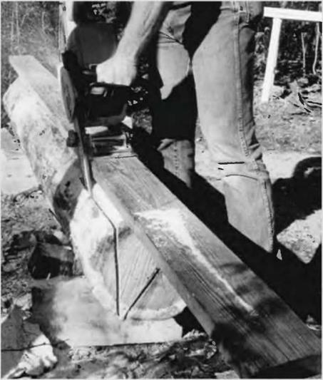
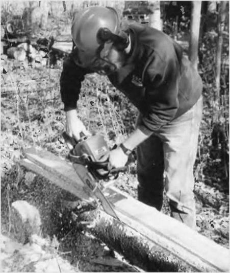
The Beam Machine is simply a 12-inch-long (30.5 centimeter) piece of channel iron welded to a pivoting mechanism which clamps onto the chainsaw’s bar with two strong setscrews. The channel iron fits neatly to the two-by-four that has been fastened along the log’s length. The mechanism allows the operator to import a vertical and straight cut as the unit is slid along the two – by-four guide track. All three of us tried the Beam Machine, and we found that we could rip the first slab off the edge of the log in about three minutes. We also tried Bruce’s saw, but it was not sharpened as well, and took considerably longer, pointing out the importance of a well-sharpened chain. We were all impressed with the smoothness of the cut using a regular chain.

After the first slab was cut away, we had a nice flat surface for remounting the two-by-four guide. Always, the Beam Machine must travel along the guide. We simply rotated the log by 90 degrees, so that we could work vertically once again on the adjacent (second) cut. We marked the small end of the log with a pencil, showing the square eight-by-eight cross-section of the beam that we wanted to make. Just before beginning a cut, we would barely tickle the end of the log with the saw to find out if we would, indeed, be cutting on the correct — outside — side of our line. On the second cut, I failed to keep the metal guide firmly on the two-by-four track and the saw came out of the other end of the log almost an inch out of plumb.

On this first test log, we also tried Bruce’s Granberg Mini-Mill, which operated on the same principle, but used a two-by-six guide instead of a two-by-four. Combined with a superior bearing for a pivot mechanism, we found the Granberg on its wider track was easier to keep on a straight vertical line. As we used the same saw, there was no difference in the time it took to make a cut.

In four cuts, we had a passable eight-by-eight post or beam, except that — thanks to my inexperience on the second cut — the last three feet of one end took a decided turn, so the cross section of that end is an inch out of square. Well, it would do as a post!

We made a nearly perfect eight-by-nine beam out of the next log, again using both machines. All dimensions were within a quarter-inch. Again, the $80 Granberg was easier to control than the $40 Beam Machine. In fairness, I think that with practice, an operator can do an adequate job with the less expensive tool, but if I were cutting a number of heavy timbers for a job, I’d say it’s probably worth the extra money for the Mini-Mill. Doug and Bruce concurred. All told, with experience, a sharp chain, and an adequately powerful saw, an eight – to ten- foot heavy timber should be possible to make every half hour with either of these simple chainsaw attachments.

image35

Fig. 3.3a: The Granberg Mini-Mill uses a wide two-by-six trackway for improved stability.


image36

Fig. 3.3b: Doug Kerr cuts a slab off a fir log with the Beam Machine.

vertically-mounted chainsaw along the rail. About $80. Again, please see the Sidebar on pages 54-55.

• Alaskan Small Log Mill. This is the smallest of the Alaskan series of chainsaw mills, “perfect for the homeowner, woodworker or carpenter who owns a 3.8 cubic inch saw with a 20-inch bar,” according to the manufacturer. The Alaskan mills employ a different sort of guide from the Beam Machine or the Mini-Mill. The saw runs horizontally along the log, not vertically. The first cut is made using a plank guide, and additional cuts run along the first cut. About $120 in 2003.

• Basic Alaskan Mill. These mills range from the 24-inch Alaskan Mill, which will make a 20-inch (51 centimeter) cut ($150), all the way to the big 56-inch Alaskan Mill which will cut a 54-inch (137 centimeter) swath through the log ($220), although I can’t imagine why you would need any more than the 20-inch cut for making heavy timbers. None of the prices, of course, include the saw, special bar, or the special chainsaw milling chain, also called a “ripping chain.” It is not recommended to try to run any Alaskan Mill with a saw of less than 3.8 cubic inches of displacement, and larger is better.

• Complete Alaskan Mills. These are big, heavy-duty items and will allow you to cut wide thick slabs easily. You can hook up two chainsaw power heads to one bar and chain, which more than doubles the effective power. These mills run from $470 to $600, and the chainsaws, bars, and chains would add a great deal to these figures. [5]

narrow-kerf ripping chain supplied by Logosol, Richard was able to cut through white pine at a rate of about 3.2 feet per minute. Richard concludes, “For the hobby wood­cutter, the Timber Jig is a $155 investment that will probably pay for itself in short order. In touting the tool as an economy lumber maker, the manufacturer may be hiding the fact that its actually an excellent timber maker as well.

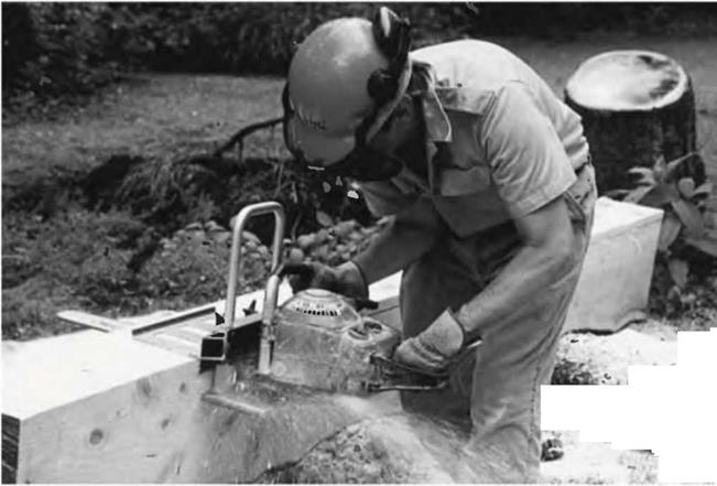
Подпись: Fig. 3.4: Richard Freudenberger tests the Logosol Timber Jig portable chainsaw mini-mill. Photo by Don Osby, reproduced by permission of BackHome Magazine, No. 66, p. 48.image37Even limited by its 8V^-inch (21.6 centimeter) depth, ripping out your own eight-by-twelve beams for a timber-frame project would save a bundle over buying them.” Richard’s complete article, with details of how to use the Timber Jig, is available in BackHome back issue No. 66. Write BackHome Back Issues, RO. Box 70, Hendersonville, NC 28793, call: (800) 992*2546 or log on to: www. BackHomeMagazine. com.

Both the Logosol and the various Alaskan Mills are a step up from the simple chainsaw guides like the Beam Machine and the Granberg Mini – Mill, and are recommended for larger projects. Yet another step up, and reflected in the cost, is the… [6]

An excellent source for purchasing many of these mills is Baileys, a woodsman’s supply house. Much of the information above comes from their 2003 Master Catalog. See Appendix C: Resources.

Making your own lumber with a chainsaw mill or bar guide is hard work, and great care must be taken both for safety and to maintain an acceptable standard of quality. Still, with a little practice, even the simplest guide attachments will yield good and useful heavy timbers.

Making timbers with a chainsaw presupposes that you are handy in the woods with the tool, as the first task will be felling the trees and maneuvering them to a clearing where you can work on the trunks. If you are not already an experienced woodsman, have someone who is teach you how to operate the saw safely and how to take down trees. Even better, take a chainsaw operation and safety course, as I should have done. I learned from experience and by necessity, but once, after about ten years of experience, I cut through a log and the tip of the saw kicked back on some hard object below. The bar, with the chain still moving, kicked back and bounced off my nose. It took a skilled plastic surgeon to make me into the good-looking guy I am today.

This book will not attempt to teach chainsaw skills. There are books and articles that do — you can search the internet — but a certified course is better. I will say that you should always wear safety chaps to protect your legs and body, and safety helmets for eye, ear and head protection. My son and I share a set of chaps, and, yes, they have been grazed on occasion. The reality is that chainsaws, handled incorrectly, can maim or kill, and so they must be treated with respect and vigilant concentration.

Having said all that, people comfortable with a chainsaw and not afraid of work can use these chainsaw mills to provide all the lumber they need, if they’ve got the trees. In a wooded building site, just clearing the house site itself, and a driveway to it, will often yield enough material to build a house. Just be careful out there!
Chainsaw Mills

There is an alternative timber procurement strategy for those with their own stand of large straight trees, and that is to make the timbers yourself with a chainsaw mill, essentially an attachment for a chainsaw. There are several different styles and qualities and costs vary a great deal. Here are some choices, with contact information for all of them found in Appendix C:

• The Beam Machine. First, you nail a two-by-four to the log that you want to make into a beam. The Beam Machine is an inexpensive ($40) bar attachment that slides along the two-by-four. Their ad says the “dog-tooth pivoting action takes most of the strain out of sawing because it supports the weight of the saw and provides you with a smooth, leveraged sawing motion.” See Sidebar, on pages 54-55. [4]

Portable Sawmills

Jim, my next-door neighbor, recently built a major addition to his house, using the kinds of timber-framing methods described in this book. He hired a local fellow with a portable bandsaw mill to come up and cut all of the timbers from logs that Jim had hauled out of his own woods. The timbers were cut straight and were of good regular dimensions.

Some of these portable mill operators charge by the hour, some by the board foot, some will do it either way. With heavy timbers, you are probably better off paying by the hour. This is what Jim did, and what he advises. He paid $35 an hour and all the heavy timbers and boards for his addition were cut in about six hours; his addition is fourteen by twenty-four feet, two stories. A lot of the wood was ash, a genuine hardwood, but this did not present a problem for the sawyer. Jim and a friend helped by rolling the logs onto the machine. He reckons that all of the timbers and lumber for a house could be done in a couple of days for about $500, once the logs have been dragged out of the woods and gathered together where the sawmill is set up.

With lots of small boards and two-by-eights, paying by the board foot might work out just as well or better. Look sawyers up in the Yellow Pages under “Sawmills.” Call and ask their rates (by the hour and by the board foot), and whether or not there is a travel or set-up charge.

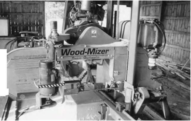
If you are blessed with having straight timbers of sufficient size on your property, hiring a portable sawmill is one of the most economical ways to obtain quality timbers. These portable bandsaws, such as Wood-Mizer and others, can make high quality timbers providing, of course, that the operator is experienced.

Timber from Small Sawmills

The wood descriptions above are general in nature. A particular species can exhibit varying characteristics depending on where it grows. A local sawyers advice is as valuable as the list above, particularly one who has many years of experience in the area.

Local sawyers charge for their lumber by the board foot. Logically, you would think that you’d get a break on price for an eight-by-eight over, say, four two-by­eights or eight one-by-eights of the same length. After all, the board footage is the same in all cases, and the sawyer has far fewer cuts to make with an eight-by-eight. You should get a price break, right? Well, I’ve never seen that happen. You pay by the board foot, end of story. The only exception is that if you give your sawyer your complete timber schedule and ask him (or her, though I have yet to meet a female sawyer) to give you a cost for the whole job, the generic “he” will take things like this into consideration, especially if there are other mills in the area.

If possible, leave your timber schedule with at least three local sawmills for pricing. But also ask about how long it will take to finish the order and whether or not they can arrange for delivery. Most sawyers are too busy to deliver on their
own, but they often know someone with a truck who can deliver the timbers to you. You can also use your own pickup truck if you are not too far from the sawmill. Several loads will be required, and fresh-cut timbers are well, heavy. Length of timber is limited to around ten feet for pick-up transport, unless the truck is equipped with an overhead wood rack. I hauled all the timbers for our new addition at Earthwood (Chapter 5) in our Nissan pick-up, but it took a few loads, at 18 miles round trip.

Подпись: Fig. 3.2: A sawyer in West Chazyt New York, tows this portable Wood Mizer bandsaw mill to private woodlots to make lumber.image34All sawyers think — or say — that they are accurate, and most are, but take a tape measure with you and quietly check out a few timbers that are already lying around. I work with two local sawyers. “Sawyer 1” has a bandsaw and “Sawyer 2” has a traditional large circular saw. Each one makes very regular dimensional timbers — I have never had a complaint about this — but Sawyer 1 sometimes lets some shoddy pieces go through: excessive wain, heart rot, large knots on the edge of the timber creating a weakness. The other guy doesn’t let this type of thing pass.

I usually end up going with Sawyer 2, even though he is a little more expensive, because of timber quality and the fact that he is reliable in having the job ready when he says it will be. Also, he will give me special attention for some of the personal quirky projects that we have going at Earthwood. Once, I needed a couple of six-by-eight posts resawn on an angle along their length. I showed up with the timbers, and he stopped production to accommodate me, and did a good job. Another time, he pulled five very cylindrical logs out of his pile for use as rollers at one of our megalithic stone workshops. This kind of service is beyond price.