Category Timber Framing for the Rest of Us Rob Roy

Timbers from Your Own Land

Some owner-builders may harvest tall straight trees on their own property to make their own timbers for their frame. Hardwoods, in general, are stronger than softwoods, but its best to compare individual species, as there is considerable overlap in strength characteristics between a list of hardwoods and softwoods. Being generally harder, the hardwoods are more difficult to nail into. You may have to drill holes and use screws to make connections. Also, hardwoods tend to shrink quite a bit more than softwoods. Here are some common woods, beginning with so-called hardwoods — which are actually deciduous or broad – leafed trees.

Hardwoods

• Ash. Quite strong and usually straight, without a lot of knots. A favorite for baseball bats and hockey sticks. Can develop large checks. The wood is a creamy white.

• Beech. Heavy, very strong and quite beautiful. However, beech has a high rate of shrinkage and can suffer from powder post beetles and carpenter ants, so it should be avoided as sill material or as posts. Save it for timbers from the first story upwards. In old timber frame work in the northern hardwood forest — before the current beech blight — beech was often the wood of choice.

• Birch, White (or Paper). Even-grained, medium strength. As a “pioneer species” in the forest, it is not long-lived, so you might have difficulty finding large diameter trees in good condition. Works quite well with hand tools or a chainsaw, when green. [1]

• Butternut. Fairly strong for its light weight. The wood is straight-grained and has fairly low shrinkage for a hardwood.

• Cherry, Black. Rot-resistant and strong. In some parts of the northeast, it is fairly common. Black cherry is a pretty wood, but, if you have it, you may want to reserve it for furniture, cabinets, or special detailing, to make boards instead of beams.

• Hickory. Probably the strongest of North American woods. I use shagbark hickory for levers when I do megalithic stone work. It shrinks a lot. Mill it fairly soon after cutting to reduce splitting.

• Locust, Black. Very strong and heavy. The only truly decay-resistant hardwood, although this should not be a big issue, unless you want to build a pole-barn building without using pressure-treated posts. Exceptional for sills or where constant weathering can be expected. Can be very difficult to work.

• Maple, Red and Sugar. Straight and non-spiral growth trees are suitable for timber framing if worked green. If the tree grows in a spiral, as it sometimes does, expect twisting in the timbers. Quite a lot of shrinkage can be expected and rot resistance is poor.

• Oak, Red. Moderate shrinkage, strong, works well. Not as decay resistant as the white oak, so keep it off of the sills. Has an attractive grain. [2]

Softwoods

• Balsam Fir. Looks like spruce, but not as strong. Very pitchy. Balsam firs snap off like toothpicks on our property during windstorms, so I presently have a low opinion of them. Still, if you choose the timbers carefully and have the stress load calculations checked over, balsam fir can do the job.

• Cedar, Northern White. This is one of my favorites for both log-ends and as timber frame material here in Northern New York. It is plentiful and inexpensive, very easy to cut and work, and plenty strong enough for the heavy-framing applications I use it for: posts, sills, and plates. I don’t use it for joists, rafters, and unsupported girders, as white pine is stronger and is also plentiful. White cedar has a pleasant aroma, without being overwhelming.

• Cedar, Red. Very rot resistant, so a good choice for sills and exposed applications. It may be hard to find trees large enough to get a quantity of heavy timbers. Great for unmilled (round) porch posts. And aromatic.

• Hemlock, Eastern. Heavy when green. While strong on bending, hem­lock is not very strong on shear. If using hemlock for girders, be sure to have the stress load calculations double-checked for shear. Watch out for “shake,” the term for separations between annual growth rings. This is, I suspect, where the low shear strength originates. Great for posts — and any timber frame needs a lot of these — but watch out for splinters. There is something particularly painful about hemlock slivers. Sobon (1994) says, “I often relegate it to areas where hands won’t touch it.”

• Pine, Eastern White. Soft and lightweight, yet plenty strong for most timber-framing applications. A pleasure to work with. White pine was popular amongst the colonists for all building purposes. Outer layers can be quite sappy. If so, you may have to dry the milled timbers in the sun a couple of weeks before handling, a good idea in any case. [3]

white, and for this reason I now go with the white if given a choice. My local sawyer agrees. Therefore, as joists or rafters, be sure to block red pine members at each end to prevent twisting. Of course, this is always good building practice.

• Spruce, Eastern. Sobon and Schroeder (1984) say, “It is a good choice for timber frames because of its straightness, small knots, light weight, strength, and resistance to splitting.” Good recommendation. My personal experience with spruce is limited to using it as tongue-in-groove flooring and as log-ends in a cordwood wall, where it has served very well for both purposes.

• Tamarack (Eastern Larch). Another log-end favorite, but I have no personal experience with tamarack (also called larch) in timber framing. Sobon (1984) says it is “A strong wood with small knots, it grows straight, is resistant to decay, and has medium shrinkage.” As with red cedar, it may be a problem finding trees large enough.

Evaluating Recycled Timbers

Recycled timbers should be carefully evaluated before you buy them or agree to dismantle a building, so carry your wish list (more correctly called a timber schedule) with you to the procurement site. Firstly, timbers have to be of sufficient sectional size and length to do the job. Use actual usable length,
allowing for damaged ends or unusable ends due to mortise and tenon joints.

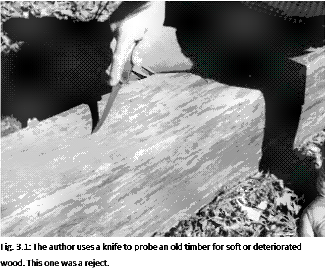
Подпись: Fig. 3.1: The author uses a knife to probe an old timber for soft or deteriorated wood. This one was a reject. Once you’ve established that you’ve got something potentially worthwhile, you need to look at each piece carefully for defects that might compromise their use on your project. With barn beams especially, all deterioration is not necessarily obvious: use a sharp knife to poke all four sides to check for soft wood. Reject any soft or “punky” pieces. Sometimes, you might get a good seven-foot post out of a twelve – foot beam, and that’s the best you can do. Catalog the piece as a good seven – footer. Do you need ten seven-foot posts? Well, here’s one of them.
Watch out for a mortise carved out of the middle of a timber that you want to use as a girder, as the void will greatly diminish bending strength. However, you might be able to use the piece as a post, or as a girt which will eventually be supported along its length by an intermediate post, or cordwood infilling.

Old timbers that have been under cover are likely to be in good condition, as are those fresh from a demolition site. However, timbers left out in the open for a year or two are almost certain to have begun a process of deterioration. It is so sad to see a beautiful old hand-hewn timber on the ground, and then to turn it over and find an inch of rotted wood on the underside. Even here, though, there is an exception. My friend Bob has some old virgin-growth heartwood timbers — twelve-by-twelves and the like — which have been lying on the ground for years and are still in excellent condition. I saw them myself, and was amazed. They just don’t make timbers like these anymore!

The use of recycled timbers may not be allowed in some code enforcement jurisdictions, because the timbers are not “graded” according to the building code — a subject already discussed in Chapter i. You need to know that you’ll be allowed to use the timbers before you spend a lot of time and money on them. As for stress load calculations, it may be hard to even judge the species of a ioo – year-old timber, never mind its grade. If we are planning to use the piece as an

important girder, it is best to use a conservatively low value as the unit stress rating for both shear and bending. If you see close-grained timbers with small knots or no knots, you know that these timbers are likely to be really strong. They’re likely to be really heavy, too.

Cultivating Coincidence

On all the buildings I’ve done with old barn timbers, I would catalog the pieces that I’d been able to procure, using a legal pad or clipboard. I’d record the sectional dimensions of each piece, its useful length, and its condition. Then I would match the cataloged pieces to my plan, to see how I could make the available pieces mesh with what I needed. Sometimes I’d have a few timbers left over — I’d save them for the next project or make them available to another owner-builder — and sometimes I’d have to seek out certain timbers to make up a shortfall. We scored timbers from a variety of sources: eight-by-eights and the like from barns within a 25-mile radius, and lots of good three-by-ten floor joists from the old Masonic hall in West Chazy, New York, as well as from an old Adirondack Inn being tom down for salvage.

I mention these finds to illustrate that it is not just old barns that yield good heavy timbers, but also old commercial buildings and even homes. The best way to increase your chances of finding material like this is to “cultivate your luck.” The more tentacles you send out into the world, the better the chances of latching on to something. Some call this networking. I think of it in mathematical terms: There are no coincidences. There is simply a probability of something happening, and the more you do to increase the number of events, the more “coincidences” come through for you. I know all this sounds very “airy-fairy,” so here are some practical tips to help you along the way. Believe me, they work.

i. Consult newspapers and pennysaver-type advertising tabloids. It is

amazing how many farmers and other country folk have timbers — or

other valuable building materials — available. In urban areas, Bob advises:

“Read the want ads religiously. The Chicago papers are good for this, but other big-city papers will be, too.” Also, you can put a “wanted” ad in yourself. This is a tentacle!

2. Go to auctions. But don’t just limit yourself to what’s being offered. Talk to other people interested in the same stuff. They may know of something they don’t need, but which would suit you to a tee. You might lose something at an auction that goes past your price, but score a better deal from someone you meet there.

3. Talk it up. Let everyone you meet know that you are looking for old timbers (or cordwood, or straw bales, or windows and doors.) More tentacles.

4. Keep your eyes peeled while traveling country roads. Don’t be afraid to knock on doors. I do this all the time to procure large stones for megalithic work, and sometimes, when I stop to ask about stones, I discover something else that the people have available. Country people don’t usually take good stuff to the dump. They keep it, thinking that they will eventually use it themselves, but, after a couple of years go by, realize that they’ll never get around to the project they had in mind and would just as soon let the timbers — or cordwood, or bricks — go to someone who will make good use of the material. Often, someone will say, “I don’t have what you’re looking for, but old Fred down at the end of the road might be able to help you.”

Send out tentacles, and the world will connect with you. Local people would say to us, “I don’t see how you get all these good deals. I’ve been here for twenty years and I never hear of deals like you get.” Our secret? We extend ourselves. Go thee and do likewise.

The Board Foot

Whether you are dealing with the local sawmill or buying salvage, you need to be familiar with the term board foot, because that is the unit by which timber is sold.

A board foot (BF) is a square foot of wood one inch thick, or 144 cubic inches (2,360 cubic centimeters) of material. Every linear foot (LF) of a full one-by-twelve board is a board foot, but every linear foot of a full two-by-six is also a BF, because it also contains 144 cubic inches of wood (2 x 6 x 12=144). A linear foot (LF) is also called a running foot at many sawmills.

This lumber scale gives the number of board feet with virtually every size of rough-cut lumber you are likely to want, in lengths from eight feet (2.44 meters) to twenty feet (6 meters).

Lumber scale, in board feet (BF)

Size Length (feet)

8

10

12

14

16

18

20

(Inches)

1 x 3

2.0

2.5

3.0

3.5

4.0

4.5

5.0

1 x 4

2.7

3.3

4.0

4.7

5.3

6.0

6.7

1 x 6

4.0

5.0

6.0

7.0

8.0

9.0

10.0

1 x 8

5.3

6.7

8.0

9.3

10.7

12.0

13.3

1 x 10

6.7

8.3

10.0

11.7

13.3

15.0

16.7

1 x 12

8.0

10.0

12.0

14.0

16.0

18.0

20.0

2×2

2.7

3.3

4.0

4.7

5.3

6.0

6.7

2×4

5.3

6.7

8.0

9.3

10.7

12.0

13.3

2×6

8.0

10.0

12.0

14.0

16.0

18.0

20.0

2×8

10.7

13.3

16.0

18.7

21.3

24.0

26.7

2 x 10

13.3

16.7

20.0

23.3

26.7

30.0

33.3

2 x 12

16.0

20.0

24.0

28.0

32.0

36.0

40.0

3×6

12.0

15.0

18.0

21.0

24.0

27.0

30.0

3×8

16.0

20.0

24.0

28.0

32.0

36.0

40.0

3×10

20.0

25.0

30.0

35.0

40.0

45.0

50.0

3 x 12

24.0

30.0

36.0

42.0

48.0

54.0

60.0

Size

Length (feet)

8

10

12

14

16

18

20

(Inches)

4×4

10.7

13.3

16.0

18.7

21.3

24.0

26.7

4×6

16.0

20.0

24.0

28.0

32.0

36.0

40.0

4×8

21.3

26.7

32.0

37.3

42.7

48.0

53.3

4x 10

26.7

33.3

40.0

46.7

53.3

60.0

66.7

4x 12

32.0

40.0

48.0

56.0

64.0

72.0

80.0

5x 10

33.3

41.7

50.0

58.3

66.7

75.0

83.3

6×6

24.0

30.0

36.0

42.0

48.0

54.0

60.0

6×8

32.0

40.0

48.0

56.0

64.0

72.0

80.0

6x 10

40.0

50.0

60.0

70.0

80.0

90.0

100.0

6x 12

48.0

60.0

72.0

84.0

96.0

108.0

120.0

8×8

42.7

53.3

64.0

74.7

85.3

96.0

106.7

8x 10

53.3

66.7

80.0

93.3

106.7

120.0

133.3

8x 12

64.0

80.0

96.0

112.0

128.0

144.0

160.0

10x 10

66.7

83.3

100.0

116.7

133.3

150.0

166.7

10x 12

80.0

100.0

120.0

140.0

160.0

180.0 200.0

12 x 12

96.0

120.0

144.0

168.0

192.0

216.0 240.0

already leaning, is to tie a cable to it and pull it down with a piece of heavy equipment, such as a tracked excavator, or a large backhoe, bulldozer, or front – end loader. Yes, a few timbers might be damaged, but this damage will usually occur at the ends of timbers, where mortise and tenon joints are torqued during the pull. With “timber framing for the rest of us,” you wont be using those old joints anyway In effect, you will be just losing some length. You can expect to get a good iz-footer out of an old 14-foot beam, for example.

Dress for the job with tough work clothing, leather or other heavy-duty work gloves, and heavy footwear with thick soles. If working inside a bam, wear a hardhat.

Procuring the Timbers

W

HEN I WAS A YOUNG MASONS LABORER IN SCOTLAND BACK IN THE 1970 S, master stone mason Hughie Mathieson would say to me, “You cannae build without the stones, Robbie, you cannae build without the stones!” It was his way of telling me to get the lead out and provide him with more building stones on his scaffold.

With timber framing, you cannae build without the timbers! Now, where are they going to come from?

Recycled Timbers

Years ago, there used to be more old timber frame barns available for salvage than there are now. Jaki and 1 used lots of recycled barn beams at Log End Cottage, Log End Cave, and Earthwood. But, recently, a large barn became available. We heard about it through a friend. As Jaki and I didn’t need timbers at the moment, and a young neighbor did, we put him onto this resource.

But even though the number of available barns has diminished, the use of recycled timbers is still a good strategy. Listen to Jim Juczak, who built a huge 18- sided timber-frame home (with cordwood infilling) near Watertown, New York:

The post and beam frame of our home is made out of recycled beams from a large bowling alley that was being demolished within six miles of our site. 1 asked the destruction foreman if I could get the wood from the ioo-foot curved trusses that were being removed. I got ten of the huge trusses, 400 sheets of used %-inch roofing plywood and about 500 pieces of 2- by 12-inch by 21-foot (6.4-meter) framing lumber. Our cost was $10,000 for what I estimated to be over $50,000 worth of materials. Disassembling the trusses, denailing the lumber, and deroofing the plywood took the better part of a summer. The curved pieces became roof rafters, the straight laminated pieces

became the eighteen vertical posts in the outside wall and the four-by material became the radial floor joists for the second floor. The first floor was radially framed with the two-by-twelve-inch material and covered with two layers of recycled plywood.

Now, $10,000 may seem like a lot, but it supplied virtually all the structural, roof sheathing and flooring materials for a beautiful 3,000 square foot home. As Jim is skilled at scrounging materials like windows, doors, and even plumbing fixtures, the total cost of the home was only about $30,000 or $10 per square foot. Jim tells the full story of this project, with pictures, in my previous book Cordwood Masonry: The State of the Art.

Jim also gives a warning: “Unfortunately, getting all this great stuff into one place can be a detriment. Last June, someone with a housing need greater than my own felt compelled to ‘borrow, without permission,’ a tractor trailer load of salvaged construction lumber from our home site.”

There are people in the salvage business who make a good living by tearing down old warehouses and the like, and selling the materials. In February of 2003, I had a lengthy and informative phone chat with my friend Bob Samuelson, a very successful dealer in recycled materials in the Chicago area. Bob built a io, ooo-square-foot lodge in Wisconsin with huge timbers salvaged from Chicago warehouses that needed to come down. The walls are made from sixteen-by – sixteen-inch timbers, laid like logs. Internal posts are huge. Roof rafters are six – by-tens. Bob’s comments were encouraging.

“Any city, small or major, has a demolition contractor, maybe several,” Bob told me, “and there are plenty of timber frame materials being salvaged all the time. Also, more and more laminated timbers are becoming available. Use the internet or the Yellow Pages to find these contractors. And it’s okay to gently bug them. They’re nice people. If they see that you are trying to do something good for yourself, they will bend over backwards to help. There are around 3,000 demo projects a year, just in Chicago, but it’s a small network and everyone knows everyone else. One person may not have what you want, but there’s a good chance that they know someone who does.”

Some demolition contractors may have recycled materials available, even old hewn timbers, but they are likely to charge a pretty penny for them, as they are in demand as atmospheric pieces in new restaurants and upscale homes. Bob says that Bill Gates of Microsoft fame used mostly recycled timbers on his big expensive house. You can’t blame people for charging what the market will bear; they’ve gone to the trouble of doing the salvage work and need to be reimbursed for their time and effort. But, many of these contractors make their money from the actual demolition, not by selling the materials. They haven’t got storage space to keep up with the rate of teardown. Bob tells me that with landfill charges of $400 to $600 a load, contractors are happy to find a cheaper way to get rid of materials, like bring them to you, for example. “You’re helping them to clean their site,” says Bob.

“Materials can be expensive or cheap and so can haulage, so shop around,” Bob advises. “If you’re not too far from the demolition site, the contractor might deliver to you fairly cheap, but if you are some distance away — say 250 miles or so from the site — expect to pay $400 to $500 for a semi load as a reasonable haulage charge.”

Bob likes to speak in large units: “semi loads.” A semi is a tractor-trailer unit, with, perhaps, a 50-foot (15.2-meter) flatbed trailer. Such a vehicle can carry up to 24 tons, which could be 12,000 to 15,000 board feet of lumber, depending on the density of the wood. This is enough lumber to frame — and complete — a good – sized home.

Bob had some other good tips. He mentioned that utility companies often have old cedar poles that they have replaced with new pressure-treated poles. Often times, only the large butt end (the part that went into the ground) was treated, usually with creosote. The rest of the pole might be in excellent condition and quite suitable for a viga-type rafter system, or tie beams, or internal posts. You can even flatten one or more sides, if you are careful to check the whole piece over for nails and spikes. A metal detector works well for this.

Summing up his commentary on salvaged material, Bob told me, “It’s still there. Old buildings with great materials are coming up all the time, sometimes with virgin growth lumber you can’t even get new.”

For a bargain on recycled timbers, you are going to have to do some legwork (see Cultivating Coincidence below) or make the effort to find the old buildings and tear them down yourself, a strategy better suited for rural areas.

Tearing down old buildings is a lot more dangerous than building a new one. Heavy timbers can fall on you, and they don’t shout a warning first. You can step on rusty nails, get poison ivy, or tangle with nasty dogs.

This is a book about building, not demolition, which is a whole different kettle of fish. The safest way to tear down an old barn, particularly one which is

Cantilever

A cantilever, as in Fig. 2.4, can be thought of as an upside down beam, supported at just one end. It is “upside down” in the sense that its top surface is in tension while its bottom surface is in compression. Note that the unsupported part of the cantilever tends to impart the same kind of upside-down stresses as the supported part. I think of it as being a bit like a first-class lever: the downward pressure of

the overhanging load pivots at the wall (which acts like a fulcrum) and causes an uplifting pressure on the supported portion.

Подпись: building to exceed the one-thirdimage25During my researches, I have found writers (some of them engineers) who say that the over-hanging part should be one-third of the supported apart. Others say 40 percent. Some say 50 percent is the absolute limit. Let us think of these numbers as parameters. Personally, I see no reason in house-
recommendation, and if there is a large load on the cantilever, I’d either Fig. 2.14: The Mushwood Cottage. consult a structural engineer or avoid the cantilever altogether.

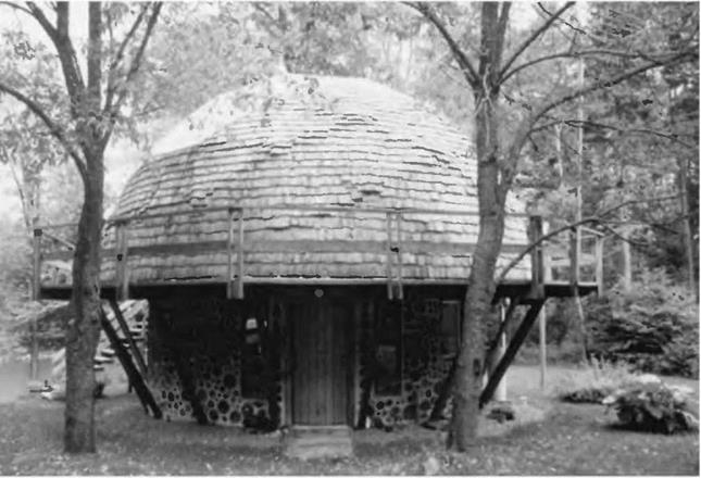
At Mushwood, our summer cottage (Fig. 2.14), the second-story 29-foot (8.8- meter) diameter geodesic dome is supported by 16 radial four-by-eight joists, which, in turn, are supported by a 22-foot (6.7-meter) diameter cordwood masonry first story and a large post at the center of the building. The overhang of the dome by itself is 3V2 feet (1 meter) beyond the outside edge of the cordwood wall, and the supported portion of the joist is 11 feet (3.35 meters). Dividing 3.5 by 11 gives 31.8 percent—not too bad at all, it would seem, but really it is not very good, as the dome is applying a concentrated load to the end of the cantilever.

In the case of a concentrated load, an overhang of 25 percent should be thought of as the limit (Clark, 1966, p. 189). However, Jaki and I wanted a three – foot walkway all around the deck, also to be supported by the radial rafters. Snow sliding off the dome accumulates on this deck, a heavy distributed load. If a lot of snow slides off the dome at once, we re looking at an impact load. Adding the 3-foot deck to the зї/2-foot dome overhang, we have a total cantilever of 6V2 feet (1.98 meters). The supported portion of the joist is still 11 feet. The new relationship is 6.5/11 = 59 percent, which exceeds anyone’s rule of cantilever by quite a bit.

We attended to the problem by installing sixteen diagonal supports, which carry the line of thrust from the dome through the diagonals (which are in compression) to the floating slab foundation that supports the cordwood

Cantileverimage26

Fig. 2.16: The principal members of this basic bent framing plan are the Posts, Tie Beam, and Rafters. The secondary members are the Interior Posts, Queen Posts, and Collar Tie. The secondary members are necessary only when bent spans exceed the structural limitations of any of the principal members. Braces are required to make this a rigid structural framework. These joints are made with fine crafted joinery, but such a bent could be constructed using mechanical fasteners and then raised into place. The drawing is by Steve Chappell, author of The Timber Framer’s Workshop (Fox Maple Press, 1999), and is used with permission.

image30

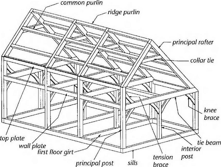
Fig. 2.18: Parts of a traditional timber frame. This drawing is only intended to illustrate framing members. Other authors and timber framers might use slightly different terminology for some of the components. Drawing by Steve Chappell and used with permission.


bent as “a transverse structural frame-work.” Jack Sobon, author of Build a Classic Timber-Framed House (see Bibliography) describes a bent as “an assemblage of timber-frame components that can be put together lying flat and then reared up into position.” He adds that bents are usually cross-frames, but adds that they can also be longitudinal wall frames.

There are no bents at our garage, in the sense of transverse frameworks, although the gable ends could have been built flat on the concrete slab and tilted up into position. The longitudinal sidewall framework could have been built that way, too. In the actual event, posts were simply stood up, individually fastened to the slab as described in Chapters 4 and 5, and the girts heaved into place and fastened together with connectors.

Fig. 2.16 shows a typical bent for a traditional timber frame. The installation of the top portion of such a bent is shown in Fig. 2.17. Four such transverse bents

Подпись: 10'8

image31

Fig. 2.19, above: Framing plan for Log End Sauna, Fig. 2.20, below: West elevation, Log End Sauna.


(two internal and one at each gable end) would be the major framework for a structure such as the one shown in Fig. 2.18, except that the upstairs of the frame in Fig. 2.18 is a little different; it is a saltbox design instead of the more common gable roof like Figures 2.16 and 2.17.

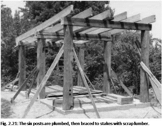
Подпись: Fig. 2.21: The six posts are plumbed, then braced to stakes with scrap lumber. You could put a plank-and-beam roof on the lower frame of a building like our garage, but we chose pre­made engineered roof trusses to support our shingled roof. The convenience, economy, and strength characteristics of pre-built engineered trusses cannot be over-emphasized, and I will speak more of them in Chapter 4.

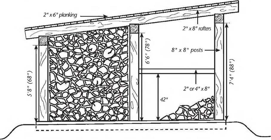
There are as many timber frame plans as there are buildings. At one end of the scale, our little cordwood sauna design consists of just 6 major posts, 3 girders, and 6 long rafters, as per Figures 2.19, 2.20 and 2.21. At the other end of the scale are houses of 3,000 square feet and more.

You can design your own structure based on the design principles in this chapter, keeping in mind the various fastening techniques described in Chapters 4 and 5. Unless you are very confident of your own engineering capabilities — or are using a tried and proven plan — you should have a structural engineer check your plans. This is a lot less expensive than going to an engineer and saying, “Please design me a timber frame for this floor plan and such-and-such a snow load.”

In New York State, any home of 1,500 square feet or greater must carry either an architect’s or an engineer’s stamp to get a building permit. (This takes the onus of responsibility off of the local building inspector.) Ki Light, a neighbor of mine, drew the plans for his post-and-beam house (with straw bale infilling) and took them to a local engineer to see if he could get his plans stamped. Ki and his wife spent a couple of hours with the man, and spoke of things like rafter frequency and span. “It took a while to explain straw bale construction to him,” Ki told me, “but, as we’d be laying up the straw bales within a heavy post-and-beam frame, he
was okay with it.” The meeting cost the Lights $100. They received some good advice, and the engineer stamped their plans. In a couple of days they had their permit.

Another strategy that has worked well for some is to bring your seat-of-the – pants structural drawings to a college engineering class and have the class check and critique the plans… under the guidance of the professor, of course!

Finally, there are two sections in Chapter 4: Building Techniques, which also contribute to an understanding of structure. They are Build Quality, Gravity and Inertia, beginning on page 87, and Roof Systems beginning on page 88. I have put them there because they cover building techniques more than structure. But they are important enough to read now, and then again when you get to Chapter 4.

Now, you will need to know where you are going to get your timbers.

Design Considerations for Rafters and Girders

As we have seen, the posts and the planks are the strong components of the post and beam (post and girder) and plank and beam (plank and joist or rafter) systems. The use of posts in scale with the girders will assure post strength. Two – by-six tongue-in-groove planking is an excellent and pleasing floor and roof system, although you should know that the true finished dimensions of this material is actually 1.V2 inches thick by about 5Vs inches wide. With frequent joists or rafters, you can easily use the lighter and less expensive “five-quarter” (full one – inch) by six-inch (<yV8 inch) tongue-in-groove planking. In reality, you can use three-quarter-inch plywood, even with an earth roof, as we did at our library. We had no sagging at all, though the greatest span on the radial rafter system was only about 39 inches (99 centimeters), and this was on the overhang.

The members that need to be engineered for are the girders, the rafters, and the floor joists. It is important to know that there are five distinct considerations that come into the design work for these members, and they are:

i. Load. You have to know what degree of load you are asking the system to support. (See Sidebar on page 31.) So, as an example, if you are planning an eight-inch-thick thick earth roof over a two-inch-thick crushed stone drainage layer, for an area with a 70-pound snow load, add the following figures from the chart: 80 (earth) + 20 (stone) + 70 (snow) + 15 (dead load) = 185 PSF.

2. Wood quality. To engineer for any beam, you have to know the stress load values for the species and grade of wood you plan to use, particularly the unit stress ratings for bending and for shear (in pounds per square inch). For example, unit stress for bending can vary from 1,100 PSI (Eastern Hemlock, common structural) to 2,150 PSI (Douglas Fir, inland region, select structural).

3. Frequency of rafters or joists. As discussed above, under the heading Plank and Beam (page 29), frequency simply refers to how many members you are using. Are the rafters on 16-inch centers? 24-inch centers?

4. Beam dimensions in section. Will you be using two-by-eights? Five-by – tens? Eight-by-eights? Vigas with a small-end diameter of six inches?

5. Clear span of the beam. This is the one that trips up most owner-builders, particularly when it comes to designing a structure to support an earth roof.

The problem is that bending strength decreases as the square of the span.

For example, lets compare a io-foot span to a 20-foot span. Instinctively, many people think that a beam has to be twice as strong to support the longer span, other considerations remaining the same. There’s a kind of logic there, but it is wrong. You’ve got to compare the squared spans. Ten times ten equals one hundred (10 X 10 = 100), but twenty times twenty equals four hundred (20 X 20 = 400). The beam carrying the 20-foot span needs to be four times stronger than the one carrying the io-foot span.

I’m going to give another less obvious example of how span (squared) influences strength, an example that pops up all the time with students at our earth-sheltered housing classes. The stress-load calculations for both the Earth wood house and the “40 by 40 Log End Cave” plans are predicated upon

nine-foot spans. These are popular designs that have been built all over North America. Invariably, people ask me if they can stretch the spans to ten feet. (Nine feet, 1 guess, seems just a little tight for them.) The answer is, of course, yes, you can do almost anything if you know what you’re doing and you have enough money. Instinctively, people figure that rafters or girders probably have to be io percent stronger to carry the extra foot of span. The math says otherwise: 9X9 = 81. But 10 X 10 = 100. The difference is 19. And this difference must be expressed in relationship to the original 81, not 100. Well, my trusty calculator tells me that 19/81 = .23457. The change will require making up a shortfall of about 23.5 percent, a considerable difference from the original engineering.

In the example above, the span has been changed, so one or more of the other four design considerations must be altered to make things right. We could decrease the load by 23.5 percent by using less earth and using a lightweight drainage product instead of a crushed stone drainage layer… or by building in Chattanooga instead of Buffalo to take advantage of the decreased snow load. We could choose a wood with 23.5 percent more bending strength, perhaps a stronger species or a higher grade of the same species. We could actually use 23.5 percent more of the originally engineered rafters by increasing the frequency, and that would take care of it. Or we could reengineer the sectional dimensions of the rafter; use six-by-tens instead of five-by-tens, for example.

You must know four of the five variables listed above to calculate the fifth. If you know load, quality of wood, rafter frequency, and span, for example, you can calculate the cross-sectional dimensions of the rafter. Or, given the kind and grade of wood, you can calculate the load that a particular rafter system will support.

If you can plug numbers into a formula, you may wish to follow through the examples of Appendix B: Stress Load Calculations for Shear and Bending. But, in reality, for more conventional (non-earth) roof systems, just use existing engineered span tables, like the one in Appendix A.

Some Typical Loads, in Pounds per Square Foot (PSF)

Подпись: Attic, where finished rooms are not a possibility = Bedrooms = Living areas = Snow load — variable — ask local building inspector = Fully saturated earth (10 PSF per inch of thickness, thus 8 inches = 80 PSF) = Crushed stone: Same as saturated earth (10 PSF) = Conventional roof framing with roofing and insulation = Heavy timber framework, roofing and insulation for an earth roof =

Note: this is the dead load. With conventional (non­earth) roofing, the dead load is included in the rafter span tables. Thus, if you are looking at a table for rafters for a zone of 70-pound snow load, the

20 PSF 30 PSF 40 PSF 10 to 100 PSF 10 PSF per inch 10 PSF per inch 7-10 PSF* About 15 PSF*

dead load is also factored into the table. With heavy frames, such as for earth roof construction, it is better to add the dead load to everything else.

Plank and Beam

“Plank and beam” roofing (or flooring) is a structural system that is often combined with post and beam framing. The confusing part here is the use of the


word “beam” in each case. For our generalized discussion, up to this point, it has been convenient to use the word beam, but now we must leave it behind in favor of more accurate —and therefore less confusing — terms. The “beam” component of the “plank and beam” system will be either a floor joist or a roof rafter, not girts or girders.

Just as posts are the naturally strong part of a post and beam frame, it is the planking that is the strong component of the plank and beam system. To give you an idea of just how strong planking can be, two-by-six tongue-in-groove decking can easily support a heavy (eight-inch or 20.3-centimeter thick) earth roof and a 70-pound snow load, with supporting rafters at four feet (1.2 meters) on center (48 inches o. c.). The earth roof described, with dead (structural) load comes to about 170 pounds per square foot. Conventional roofs in our area are required to support 70 pounds per square foot.

So engineering problems will not be found in the strong planking. The situation described in the preceding paragraph calls for some extra heavy-duty girders and rafters to support such an earth roof if the rafters are 48 inches on center. By the way, with a parallel rafter system the term “on center” refers to the distance from the center of one rafter to the center of the next. With normal framing, on-center spacing of floor joists is typically 12 inches (30.5 centimeters), 16 inches (40.6 centimeters), or 24 inches (61 centimeters). With heavy timber construction, other on-center spacing may be appropriate. At our Log End Cave earth-sheltered house, it was convenient to use a spacing of 32 inches (81.3 centimeters) on center. This worked out well with the predominantly eight-foot (96-inch) planks we used.

The number of rafters used, a function of the on-center spacing, is also known as the frequency of the rafters. The strength of the roof system (all else being equal) is a direct linear function of the frequency. If “direct linear function” throws you, think of it by way of a simple example. If you double the number of rafters (with spans, loads and rafter quality staying the same), you will, in fact, double the strength. You will be able to support twice the load with twice as many rafters by placing rafters on 12-inch centers instead of on 24" centers. This is an easy, if expensive, way to increase the shear and bending strength of a roof system.

Post and Beam Frame

The “beam” component of “post and beam” timber framing usually refers to a heavy top plate, sometimes called a girt, or it could refer to a girder. Girts will often be supported later by infilling the individual panels of the building’s perimeter. In this book, I use the word “panel” to refer to the spaces between posts around the perimeter. Girts can also gain strength by the use of intermediate posts, between the major posts. If not called upon to provide a joining surface for two consecutive girts, these intermediate posts can be less substantial, thus less expensive. An example of this is our garage at Earthwood. See Figures 2.12 (photo) and 2.13 (post and girt plan.) We have full-sized eight-by-eights at each corner of the 24-foot by 28-foot (7.3-meter by 8.5-meter) structure. In addition, we have eight-by-eights halfway along the walls. But, providing further strength to the girts, we have what I think of as secondary posts, still substantial four by-eights, laid up so that the eight-inch (20.3 centimeter) dimension corresponds with the 8-inch thickness of the wall. The sides of the building, therefore, have four panels

on the long side, each about seven feet in length including the posts, and also four panels on the south (gable) side, each about six feet long. The 24-foot­wide north side features a 16-foot garage door, with little four-foot panels on each side. An 18-foot-long (5.48- meter) eight-by-eight carries the girt system over the garage door. This large beam can also be thought of as a giant lintel over the garage door.

I was told at a building supply that the rough opening for our double garage door was 8 feet high and 16 feet wide, and it was framed accordingly. In reality, the height dimension turned out to be seven, not eight, feet (2.13 meters). The door fit with a foot to spare. We later hung a horizontal two-

by-eight from the eight-by eight with 10-inch pieces of two-by-eight material, filling the spaces with cordwood masonry. Because of this mistake, our garage is actually a foot higher than it needed to be, causing me to do a bit of extra cordwood work.

In the case of the girts at our garage, they were well-supported during construction, with temporary diagonals screwed to the external frame to prevent racking of the building due to wind loads. Later, individual diagonals would be removed and panels would be filled in with cordwood masonry, which also serves to prevent racking. We do not have any true girders at our garage, as we have at the Earthwood house. It is the clear-span girders in a post and beam frame that need to be engineered for both shear and bending. Appendix В gives an example of this.