Category RENOVATION 3

INSTALLING BASE CABINETS

Cabinet installers wrangle about whether it’s easier to install base or wall cabinets first. If you hang the wall units first, you won’t need to lean over the base cabinets as you work. Whereas if you install the bases first, you can brace the bottom of the wall cabinets off the bases and thereby install the uppers single-handedly.

There isn’t one right answer, but the photos on p. 318 make a convincing case for hanging the wall cabinets after installing stone countertops. Above all, be patient. Setting cabinets means endlessly checking and rechecking for level, fussing with shims, and so on. So don’t begrudge the time it takes. You can’t hurry love or cabinets.

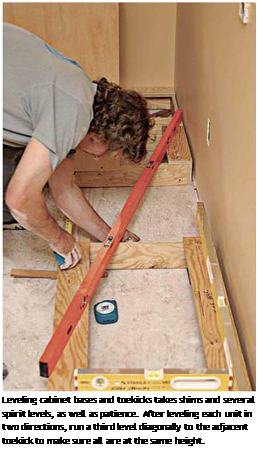
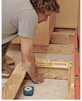
Setting rough toekicks. If your cabinets have separate toekicks, install them first, starting at the highest point on the floor—as you did dur­ing layout. Make the toekicks as long as possi­ble to minimize joints because joints tend to sag and separate under load. Level the toekicks side to side, front to back, and from section to section. Shimming is an inexact science: As a rule of thumb, shim under the corners and in the middle of a span—roughly every 18 in. to 24 in. A 24-in.-deep base cabinet is typically supported by a 20-in.-deep toekick.

image633

Because you’ll be securing both base and wall cabinets to stud centers, use an electronic stud-finder to help locate them.

If floors are seriously out of level—say, 1 in. in 8 ft.—construct several ell supports such as the one shown in the top right photo on p. 308. Screw one leg of each ell to the subfloor, level the top of the toekick, and then screw the side of the toekick to the upright leg of each ell. Ells aren’t hard to construct, and they’re far more stable than a 1-in.-high stack of shims. Once you’ve lev­eled the toekicks, place the base cabinets atop them and see how everything fits together. If this dry run looks good, set aside the cabinets and screw the toekicks to the subfloor.

LAYING OUT CABINETS

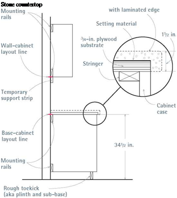
Using a long level atop a straightedge, locate the high point of the floor. It’s easier to set a base cabinet (or rough toekick) at the floor’s high point and shim up the other cabinets to that level than it is to cut down cabinet bases and toekicks. From the floor’s high point, measure up the height of a base cabinet (usually 34h in. high) and mark the wall. Use a laser level, as shown in the top left photo on p. 45, to transfer the base cabinet mark to other walls, creating a level line around the room, which we’ll call the base cabi­net layout line.

Marking off elements. Along the base cabinet layout line, mark off fixed elements, such as the stove, range hood, and refrigerator. Often, a sink cabinet will center under a window. If upper cab­inets are to frame a window evenly on both sides, mark the edges of those cabinets. Once the large elements are marked onto the walls, mark off the widths of the individual cabinets. For frameless cabinets, measure from the outside of the side panels. The frames of face-frame cabinets extend slightly beyond the side panels, creating slight gaps between the boxes. Much of the time, the sides of wall and base cabinet units will line up vertically because they are the same width.

Wall cabinets. Use the base cabinet layout line to establish the bottoms of wall cabinets, too. Because wall cabinets are normally placed 18 in. above the finish countertop, measure 19h in. up from the base cabinet layout line to position the bottoms of the wall cabinets; shoot a laser level through that mark and lightly pencil a second level line around the room, which is the wall cab­inet layout line. Over refrigerators and stoves, the bottoms of the wall cabinets will be higher. If you are also installing full-height pantry or broom cabinets, make sure their tops align with the tops of the wall cabinets; if they don’t, raise or lower the wall cabinets till the tops line up. Next mark off the width of the wall cabinets along the wall cabinet layout line.

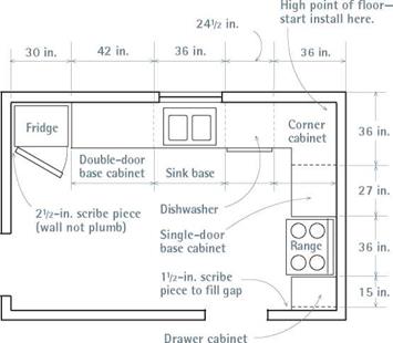
Scribe locations. Layout marks should also include scribe locations, where you must install a narrow scribe piece (filler strip) to cover a gap between cabinets and an appliance or a space between an end cabinet and an irregular wall. Where cabinets meet at inside corners, 1 h-in.- or 2-in.-wide scribes are often needed to offset drawers or doors slightly, so they have room to pull past the cabinet knobs or appliance handles sticking out from the adjacent bank of cabinets.

Подпись: Leveling cabinet bases and toekicks takes shims and several spirit levels, as well as patience. After leveling each unit in two directions, run a third level diagonally to the adjacent toekick to make sure all are at the same height. Подпись: To make rough toekicks, rip down 3/4-in. plywood, which is more durable and water resistant than particleboard should there be a leak. Don't use 2x4s because they are rarely straight enough to use as a sub-base for cabinets. Besides, rough toekicks must be 4 in. high, and a modern 2x4 placed on edge would be just 31/ in. high. 1111

Подпись: INSTALL THE loekick FIRST If finish floors aren't yet installed and you don't want the cabinets dinged up by the flooring installers, then install only the toekick initially, shimming it level and screwing it to the subfloor. This is especially recommended if you'll be laying tile floors because mortar and grout are messy. Then flooring installers can run the flooring snug to the toekick, covering the shims. When the flooring is complete, simply place the base cabinets atop the level toekick and screw them down. When constructing the toekick, increase its height by the thickness of the finish floor, so the top of the toekick will be 4 in. above the finish floor. If you're installing tile over a mortar bed (1 in. to l1/ in. thick), make the rough toekick 5 in. to 51/ in. high.

Marking studs. Finally, find and mark stud cen­ters, to which you’ll screw the cabinets. To find studs, either use an electronic stud-finder, rap the walls with your knuckles, or drive small finish nails into wall areas that will be covered by cabi­nets. Whatever works! Use a spirit level to plumb light pencil lines that indicate the stud centers. It’s desirable to screw into as many studs as you can to secure wall cabinets, but screwing into only one stud is acceptable for base cabinets and for narrow wall cabinets that don’t reach two studs.

Cabinet Basics

Cabinets today are basically boxes of plywood, particleboard, or medium-density fiberboard (MDF) panels that are glued and screwed together. Side panels, bottoms, and partitions are typically 3/ in. thick; back panels are usually in. thick. Cabinet faces are either frameless (the edges of the panels are the frame, although they may be veneered or edge-banded) or face frame (a four-sided wood frame covers the edges of each box).

Factory-made cabinets are frameless (also called European style). Having fewer elements and a simpler design, they are easier to manufacture. (The cabinets shown in the installation photos are frameless.) Doors and drawers typically lie flush on the case and overlay the panel edges. Usually, there’s % in. between the door and the drawer edges.

Face-frame cabinets are a bit more work, but offer more visual variety. You can expose more or less of the frame, vary the gaps between drawers and doors, use different hinge types, and so on. In general, designers who want a more ornamental, less severe, more traditional look often specify face-frame cabinets.

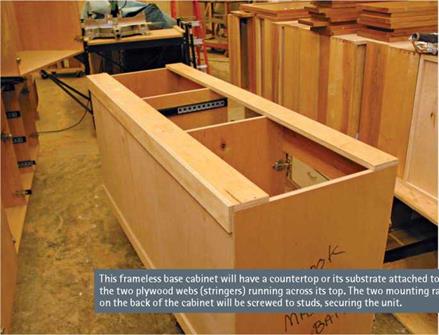
In addition to the elements above, cabinet cases have nailers (mounting rails) that you screw through to secure the cabinets to the studs. Base cabinets also have stringers— plywood webs across the top—to make boxes more rigid, keep partitions and sides in place, and provide something solid to screw the countertop to.

Kickspaces

The indentation at the bottom of a base cabi­net that provides room for your toes, so you can belly up to the cabinet while prepping food or doing dishes, is called the kickspace. Without a kickspace, you’d need to lean for­ward to work at the counter—a sure recipe for backaches. Custom-made cabinets sit on a separate rough toekick (also called a plinth or sub-base), which is often assembled on site; whereas most (but not all) factory-made base cabinets arrive with toekicks built in. Toekicks are covered by a kickface, or finish toekick, a %-in. plywood strip with the same finish as the cabinets or a vinyl strip; the kickface is better installed after the finish floor.

Scribes

Cabinet assemblies also include small but important filler strips called a scribe pieces. These typically have a rabbeted back so they can be easily be ripped down to fill gaps between cabinets or between a cabinet and a wall. On a frameless cabinet, a separate scribe piece may be attached to a side panel, near its face; whereas on face-frame cabinets, the frame stile (vertical piece) has a rabbeted back edge (for scribing). In addition, many cabinet side panels extend slightly beyond the back panels, so those side panels can be scribed to fit snugly to the wall, as shown in the top left photo on p. 311. Custom cabinet­makers often create a separate scribe panel to dress up the end cabinet in a run and cover any gaps along the wall.

Better-grade cabinets have mounting rails on the outside of back panels so the rails are not visible inside the cabinet case. The edge detail shown in the enlargment is typical. The countertop substrate—here, 3/4 in. plywood-screws to stringers at the top of the cabinet case. Screw the cabinet bottom to the rough toekick.

Подпись:Подпись:image630Подпись: Cabinet-Mounting and Edge DetailsПодпись: Stone countertop the cabinets—and review those measurements and conditions again after the cabinets arrive.

Kitchen Lighting Basics

at the sink, position it at the base of the U, with the refrigerator on one side and the stove on the other. If one person preps food or washes while the other cooks, their paths won’t cross too often. If possible, place the sink beneath a window so the eye and the mind can roam.

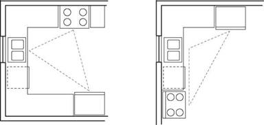
L-shaped kitchens are popular because they allow various arrangements. That is, you can put a dining table or a kitchen island in the imagi­nary fourth corner. However, this becomes a somewhat less efficient setup if one leg of the L is too long. Again, position the sink in the middle.

Подпись: U-SHAPEПодпись: L-SHAPEimage626image627

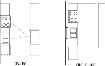
Подпись: Single-line kitchens, common to small apartments, are workable if they're not longer than
Подпись: Kitchen Lighting should be a combination of natural light (windows), general lighting, and task lighting to illuminate specific work areas. For light that is both warm and efficient, combine incandescent and fluorescent bulbs. Warm fluorescent lights are another option. General lighting can come from overhead fixtures, recessed ceiling lights, track lighting, or perimeter lighting. Mount ceiling lights 10 in. to 12 in. out from cabinet faces to illumi-nate kitchen surfaces evenly, while minimizing shadows cast by wall cabinets or by people using the counter. For an average-size kitchen (75 sq. ft. to 100 sq. ft.), ceiling-mounted general lighting should total about 200 watts incandescent or 80 watts fluorescent; if there's recessed ceiling lighting, four 100-watt incan-descent bulbs should be enough. For larger kitchens, figure 2 watts of incandescent or 1 watt of fluorescent light per square foot of kitchen area. Task lighting over sinks and cooktops should be at least two 75-watt incandescent bulbs or two 30-watt fluorescent bulbs. Ideally, task lighting should be placed behind a face trim board of some kind, so that the bulbs shine more on the work surface than in one's eyes. To illuminate countertops, task lighting is often installed under wall cabinets, hidden by face board or a cabinet rail. Low-voltage halogen "puck" lights or slim-line fluorescent bulbs can be shielded by a face board that's only 11/ in. high. In general, under-cabinet lights should be two-thirds as long as the counter they illuminate.
Подпись: | Common Kitchen Layouts

Galley kitchens create efficient work triangles, but they can become hectic if there’s through traffic. If you close one end of the galley to stop traffic, the galley should be at least 4 ft. wide to accommodate two cooks. To avoid colliding doors, never place a refrigerator directly across from an oven in a tight galley kitchen.

Подпись: A Cornucopia OF CABINETS Custom-made cabinets are still the gold standard on most jobs, but better grades of factory-made cabinets are increasingly well made and cost competitive. That is, you can order fine cabinets by mail and expect to receive tight joinery, matched wood grain, and excellent finishes. Cabinet parts from different sources are uniformly sized and virtually interchangeable, so you can mix and match thousands of cabinet cases, doors, drawers, and hardware types. Подпись: I Adding Cabinets, Refining the Layoutimage62812 ft. and there’s a minimum of 4 ft. to the oppo­site wall. Compact, space-saver appliances can maximize both floor and counter space.

Islands are great in multiple-use kitchens, for they can provide a buffer between cooking tasks. To make sure the island doesn’t interfere with the work triangle, keep 4 ft. to 5 ft. of open space for nearby counters and appliances.

KITCHEN CABINET LAYOUTS

Once you’ve chosen a work layout that you like, make to-scale floor plans: A % in. to 1 ft. scale provides a good amount of detail for a single room yet still fits on an 8/2-in. by 11-in. sheet of graph paper. Include windows, doors, appliances,
and cabinets. You may find it helpful to cut to-scale rectangles to represent the refrigerator, sink, and cooktop. If you cut them from different colored paper or label each piece, you’ll have an easier time trying out your layouts.

Basic layout. Refining the layout is a fluid pro­cess, but a few spatial arrangements are so com­mon they’re almost givens. Place the sink under a window. Don’t put a refrigerator and a stove side by side because one likes it hot; the other, cold. In general, place the refrigerator toward the end of a cabinet run, so its big doors can swing free. When the appliances are comfortably situated, fill in the spaces between with cabinets.

Try not to fit cabinets too tightly to room dimensions. If you’re fitting cabinets into an older house, it’s safer to undersize cabinet runs slightly—allow 1 h in. of free space at the end of each bank of cabinets—so you have room to fine – tune the installation. You can cover gaps at walls or inside corners with scribed trim pieces. Speaking of inside corners, allow enough room for cabinet doors to open freely.

Cabinet dimensions. Basically, there are three types of stock cabinets: base cabinets, wall cabi­nets, and specialty cabinets.

► Base cabinets are typically 24 in. deep, and 34І2 in. tall so that, when a countertop is added, the total height will be 36 in. Base cab­inet widths increase in 3-in. increments, as do wall cabinet widths. Single-door base cabinets range from 12 in. to 24 in. wide; double-door base cabinets run 27 in. to 48 in. wide. Drawer cabinets vary from 15 in. to 24 in. wide. Tray units are generally 9 in. to 12 in. wide.

► Wall cabinets are 12 in. to 15 in. deep, with 12 in. being the most common depth.

They vary from 12 in. to 33. in. high. Wall cabinet widths generally correspond to base cabinet widths, so cabinet joints line up.

► Specialty cabinets include tray cabinets, base corner units, corner units with rotating shelves, tall refrigerator or utility cabinets, and wall-oven cabinets. Specialty accessories include spice racks, sliding cutting boards, and tilt-out bins. Specialty cabinet dimensions vary, not always in predictable increments. Base sink cab­inets range from 36 in. wide (no drawers on either side) to 84 in., typically in 6-in. increments.

Подпись: After numerous refinements, your kitchen layout should be tight enough to take it to a home center and get an estimate on the cabinets. Or you can go online, where numerous Web sites will walk you through measuring and ordering. IfПодпись: Once you choose a layout that works well, use base cabinets to tie appliances and work areas together. On your floor plan, note room irregularities that could affect layout and installation. Using light pencil lines, mark cabinet and appliance locations onto the walls.
ORDERING CABINETS

you’ve never ordered cabinets before, it’s smart to hire a finish carpenter to help figure out exactly what you need.

Before ordering cabinets, clean up floor plans and elevations, and survey the kitchen one last time, noting window, door, and appliance loca­tions; electrical outlets, switches, and lights; and plumbing stub-outs (protruding pipe ends before hookup)—in short, every physical aspect of the space. Carefully remeasure the room and note potential problems such as sloping floors, walls that are wavy or out of plumb, and corners that aren’t square or that have excessive joint com­
pound that could interfere with installation. Most of these irregularities can be corrected by shim­ming cabinets to level and scribing end panels to cover irregular surfaces, but you need to know about them beforehand.

Installing Cabinets
Подпись: PRO"ГIP When cabinets arrive, inspect the packaging for signs of abuse or breakage—crushed corners or torn cardboard—before unwrap-ping them. Make sure the cabi-nets and hardware are the styles you ordered, and cross-check your order against the shipping invoice to be sure all parts are there. Report damaged or missing parts immediately. ■ ill The key to a successful cabinet installation is lev­eling the base and wall cabinets and solidly securing them to wall studs and to the floor. As noted earlier, carefully measure and assess the kitchen walls, floor, and corners before you order

Kitchen Lighting Basics

image629

. Standard Cabinet Dimensions

Letter refers to "Figuring Dimensions" at left.

. Standard Cabinet Dimensions

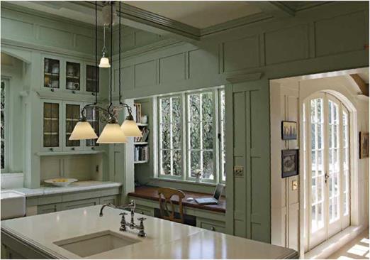
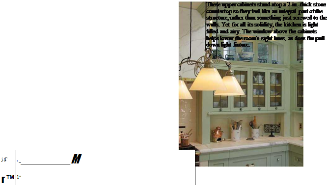
The arched valance over the farmhouse sink picks up curves in other rooms, including the double doors to the dining room, at right. In between, is a quiet alcove with enough room for cookbooks, a chair, and a computer.


image623

Recommended Counter Space and Clearances


Minimum Kitchen Work-Space Clearances


SPACE DIMENSION (in.

In front of base cabinet

36

Between base cabinet and facing wall

40

Between facing appliances

48

Work space plus foot traffic

60


image624

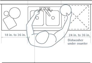
Подпись: Each work area-food prep, cooking, and cleanup-should have adequate counter space so a cook can work efficiently, with enough clearance to move safely. Counters with dishwashers underneath must be at least 24 in. wide; otherwise, 18 in. is the minimum. See “Minimum Kitchen Work-Space Clearances," at right.image625

a slight bend to your elbow. If the standard counter height of 36 in. above the finish floor isn’t right for you, lowering or raising it an inch or two may do the trick. However, if you’re think­ing of selling the house fairly soon, your ideal counter or shelf height may not appeal to the average buyer.

Equally important are the clearances needed to move easily in a kitchen—clearances that homeowners frequently overlook when laying out new kitchens. Be sure to allow enough room to open cabinet doors fully and still walk around them. Traffic lanes through work areas are vital because cooks frequently handle hot, sharp, or heavy objects: thus keep a 60-in. minimal clear­ance if the work area doubles as a corridor. Ideally, though, family traffic should bypass the cooking space. So if a kitchen has two or more doors, you may be able to reroute that unwanted traffic by eliminating one of those doorways, while gaining counter and cabinet space in the process.

COUNTER AND CABINET SPACE

Meal preparation consists of food prep, cooking, and cleanup, ideally with counter space for each job. Prepping the food—washing, cutting, and mixing—takes the most time, so give as much space as possible to counters near the sink and the cooktop.

Sink counters should be 24 in. wide on each side of the sink, though 36 in. is better, allowing plenty of room for food prep and the air-drying of pots and pans. Because dishwashers are 24 in. wide, they fit neatly under a 24-in. counter. If the kitchen is tiny and there’s no undercounter dish­washer, 18-in.-wide sink counters are minimal. Have a splashback behind the sink.

Cooktop counters should be at least 18 in. to 24 in. wide on both sides of the unit, and at least one side should be made of a heat-resistant mate­rial. Placing a stove on an exterior wall keeps exhaust-fan ducts short, but never place a gas stove in front of a window because a draft could blow out burners. The wall behind a stove should be washable.

By the refrigerator, next to the latch side, have a counter at least 15 in. wide so you can place things there as they go in and out of the fridge. If the refrigerator and the sink share a counter, the space should be 36 in. to 42 in. long. Because this counter is typically a food-prep area, you’ll need a large surface to store countertop appliances.

Cabinet space has few rules. The best indicator of how much cabinet space you need is the num­ber of appliances, bowls, and paraphernalia you own. Or use this rule of thumb: Figure 18 sq. ft. of basic storage plus 6 sq. ft. for each person in the household.

OUTLETS

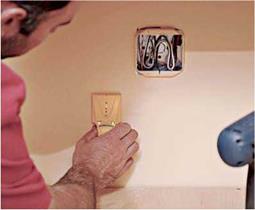
Kitchen counters 12 in. wide or wider must have at least one electrical receptacle to serve them. All points on a counter must be within 2 ft. from a receptacle, and all counter receptacles must have ground fault circuit interrupter (GFCI) protection. Chapter 11 addresses this.

LAYOUT CHOICES: WORK AREAS

The person preparing and cooking the meal moves primarily in a space bounded by the refrigerator, the stove, and the sink—the so-called work triangle. When laying out such work areas, designers try to keep the distance traveled between the three points within 12 ft. to 22 ft. Three of the layouts shown below feature a work triangle. The fourth is a single-line kitchen, but the distance traveled should be roughly the same.

U-shaped kitchens are the most practical because they isolate the work area from family traffic. Because the cook spends most of the time

Kitchens and Baths

Подпись: Built in an Edwardian-Era spirit, this Piedmont, California, kitchen has 11-ft. ceilings; a massive marble and brass stove hood; a porcelain, steel, and cast-iron stove; and 2-ft.-sq. colored cast-concrete floor tiles you can clomp around on in big shoes.image621

No other rooms are renovated as often as kitchens and bathrooms, in part, because we’ve changed the way we live. In the old days, home­owners regarded kitchens and bathrooms as drab utility rooms, best situated at the back of the house, away from guests. Times change. These days, if you throw a party, everybody hangs out in the kitchen. Bathrooms aren’t exactly Spartan anymore, either. Today’s kitchens and baths contain so many cabinets, counters, fixtures, and appliances that it takes careful planning to make them all fit—and still have room for people to move around. This chapter will help with that.

Kitchen Planning

The best kitchens can accommodate your per­sonal tastes and lifestyles as well as your physical characteristics, such as your height.

WHAT GOES ON IN YOUR KITCHEN?

Start planning by imagining a day in the life of your kitchen, being as specific as possible about the activities—and the actors. Do you want a sunny spot to have coffee, read the paper, and wake up? Will the kitchen table double as a desk for homework? Or will the kitchen be a com­mand center in which you field calls and arrange after-school carpools while tossing the salad?

Keep a notebook in your present kitchen and jot down observations about what goes on—as well a wish list for what you’d like changed. Many entries will be cooking specific: Is there enough storage and enough counter space to prep several dishes? Does the cook like company? When you entertain, how large is the crowd? Is there a con­venient place for cookbooks? Such considerations will be useful in evaluating your kitchen and establishing priorities for the new one.

CABINET HEIGHTS AND CLEARANCES

Over the years, architects, appliance designers, and builders have adopted a set of physical dimensions that, in theory, make kitchens safer and easier to use. As shown in "Figuring Dimensions” below, these dimensions work for most people but, in the end, may not suit every­body. As a rule of thumb, a counter is the right height if you can place your palms flat on it, with

REFERENCE* SPACE

Replacing a Water Heater

Most municipalities require a permit to replace a water heater, primarily because they want to ensure that the heater’s TPR valve is correctly installed. Even though most local codes allow homeowners to replace water heaters, unless you have a lot of plumbing experience, hire a licensed plumber for this job. Plumbers know which brands and hookups require the fewest service calls and can assess the condition of vent pipes and replace them if needed. Besides, thanks to wholesale discounts, plumbers can probably install a new unit for only slightly more than it would cost you if you bought the heater and fit­tings at retail prices.


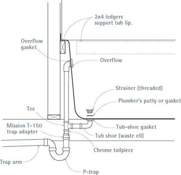
If the tub drain is not accessible, plumbing codes require that joints be glued together, to prevent leaks. To join the tub tailpiece to the trap assembly, use a Mission T-150 trap (1V2-in. tubular to 1V2-in. pipe).


image612image614

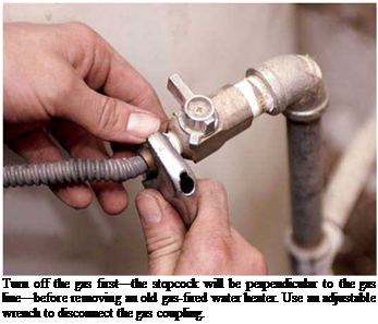
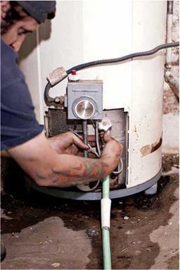
Подпись: Turn off the gas first—the stopcock will be perpendicular to the gas line—before removing an old gas-fired water heater. Use an adjustable wrench to disconnect the gas coupling. Подпись: PROnP Don't accept water heaters whose boxes are bashed or torn. Water-heater elements are sensitive. If the box has been handled roughly or dropped, anode rods, liners, or valves may have been damaged. llll

A plumber should also be willing to peer through the vent thimble with a flashlight and mirror to check the chimney’s interior. All man­ner of debris can accumulate in the bottom of a chimney—from soot to nests—and that debris can block a chimney, hamper flue draft, and pos­sibly force carbon monoxide into living areas. The National Fire Protection Association sug­gests annual chimney and flue inspections, and

image616

Once the gas line is disconnected, attach a hose to the drain at the bottom of the water heater and drain the tank.

whenever a new type of burning appliance is vented into the flue, but inspection is really not a plumber’s job. The Chimney Safety Institute of America offers a state-by-state listing of chimney services with certified staff (check out their Web site at www. csia. org).

Above all, installers should follow the water – heater manufacturer’s installation instructions closely to ensure a safe installation and to safe­guard the unit’s warranty should the water heater fail to function properly.

Draining the old water heater. The specifics of disconnecting power or fuel to the old unit will vary, depending on whether the water heater is gas fired, fuel-oil fired, or electric. Once the installer has disconnected the fuel or power source, the water should be shut off and the tank drained. Typically, a hose will be attached to the drain valve at the bottom of the tank. Using a pair of pipe wrenches, unions (if any) on the hot – and cold-water pipes will be taken apart; if there are no unions, pipes will be cut 6 in. to 12 in. above the top of the heater—or a couple inches above the cold-water shutoff valve—by means of hacksaw or a wheeled cutter. Caution: Recipro­cating saws aren’t used because the vibration may weaken nearby pipe joints and cause leaks.

Make way for the new. If the unit is gas or oil

fired, the installer will disconnect the draft hood and vent pipe and either wire them up out of the way or set them to one side. As noted earlier, the plumber should inspect the vent pipes. If the hood or pipes are rusty or corroded, they should be replaced. When the old tank is empty, it can be walked out of the way. Be mindful of sharp edges on the newly cut pipes and the area around the old tank. Note: If codes require strapping the unit, steel straps should be bolted to the wall behind before putting the new unit in place. Finally, if the pad beneath the old tank is in poor condition or badly tilted, consider installing a new prefab concrete pad. Then the new water heater can be walked into position.

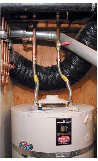
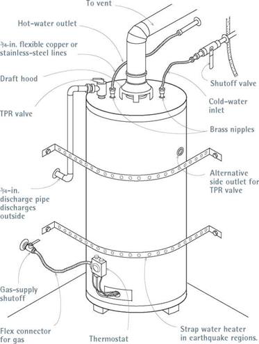
Making connections. What the installer does next depends on the size and condition of the pipes, what fittings are present and, of course, what type of water heater it is. There’s no single right way to assemble pipes, but the photos at left show a typical installation in progress for a gas – fired unit. There are 14-in. brass nipples screwed in the tank inlet holes, flexible stainless-steel lines, sweat-to-threaded male adaptors, valves, and (at the top) 14-in. rigid-copper trunk lines exiting to the upper floors. Flexible stainless-steel or flexible copper supply lines are highly recom­mended for top-of-tank connections: Female nuts

Подпись: When replacing a water heater, put unions and lever- handle ball valves on both the hot- and the cold-water pipes. Code requires a shutoff valve only on the cold-water pipe, but having them on both can make periodic drainage and repairs easier.Подпись: llll

on both ends make them easy to disconnect for future repairs.

Installing a TPR valve. Many new water heaters have preinstalled TPR valves. If there is none, the plumber will install a TPR valve into the threaded outlet atop the unit or in a side outlet a few inches down from the top of the tank, lightly coat the TPR valves threads with pipe compound, and then use a pipe wrench to install the valve. Next, the plumber will install a discharge pipe into the TPR valve’s threaded outlet; the pipe may be gal­vanized or rigid copper—but not plastic!—and must slope downward. The discharge pipe should be terminated about 6 in. above the floor, at a safe location, where it won’t scald anyone if it discharges.

Note: Threaded pipe fittings should be coated with pipe compound or wrapped with Teflon™ tape to ensure a positive seal.

Final steps. The plumber will check the water heater for level, shim the base as needed, and tighten the earthquake straps, if any. When all fittings are connected, turn on the cold water to fill the tank. Open the hot-water faucets to expel air. When the tank is full, water will gush from the faucets. At that point, shut the faucets, and reconnect the fuel or power source as specified in the manufacturer’s instructions. Note: If the installer disconnected the bonding jumper wires from the hot – and cold-supply pipes, those wires should be reclamped now to ensure proper grounding for the house’s electrical system.

image617

A new gas-fired water heater, in mid-installation. The red lever-handled shutoff valve on the cold – water pipe is code required; the tempering valve on the hot-water pipe prevents scalding. After installing the TPR safety valve, plumbers will reattach the vent pipe.


Gas-Fired Water Heater


image618

INSTALLING A BATHTUB

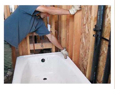
After framing the three-walled alcove around the tub, attaching 2×4 ledgers to support the tub lip, and cutting an opening in the subfloor for the drain assembly, dry-fit the tub and check for level in two directions. If the tub rocks after its lip is supported by the ledgers, remove the tub, apply 30-lb. building paper over the subfloor, and pour 1 in. to 2 in. of mortar. Place the tub in the mor­tar before it sets, so the mortar will conform to the shape of the tub. If the tub is made of cast- iron be sure to have at least three workers on hand to move it.

Drain and overflow assembly.

Before the final installation of the tub, preassemble the tub’s drain and overflow assembly and test-fit it to the tub open­ings. Slip-nut couplings make adjusting pipe lengths easy.

Once the tub back is in the alcove, install the assembly in the tub: Put a layer of plumber’s putty between any metal-to- enamel joint that isn’t gasketed.

While a helper holds the assem­bly to the end and underside of the tub, hand screw the threaded strainer into the tub shoe (waste ell). Then use a strainer wrench

to tighten it solidly. The overflow plate inside the tub screws to a mounting flange in the over­flow ell. There are many types of drain cap (stopper) mechanisms; follow the manufacturer’s instructions.

The last drain connection to be made is a P-trap, which slides onto the tub tailpiece descending from the tee. Adjust the trap so that it aligns with the branch drain roughed in earlier. Note: If the drain assembly will be inaccessible, code requires a glued-together drain joint. The only exception allowed is the slip-nut coupling that joins the tub tailpiece to the P-trap.

Water supply. Next, attach the tub’s supply pipes. Level and mount a pressure-balancing valve to the cross brace let into the end-wall studs.

(The valve, also called an antiscald valve, is typi­cally set at a maximum of 120°F to prevent scald­ing.) Follow the manufacturer’s instructions for attaching the pipe to the valve. Although gate and ball valves are usually closed when sweating cop­per pipe to them, balancing valves may need to be open or disassembled before sweating pipe to the valve bodies.

Like most shower/tub valves, a balancing valve has four pipe connections: one each for hot – and cold-supply pipes, one for the pipe that runs to the shower arm, and one that services the spout. To mount shower arms and spouts, screw brass, threaded female drop-eared ells to the cross braces. Because chrome shower arms and spouts can get marred while finish surfaces are being installed, screw in 6-in. capped galvanized nipples. The faucet stem(s) and the balancing valve are protected with a plastic cover till the finish work is done. Turn the water on and test for leaks. Once you’re sure there are none, you are ready to close in the walls around the tub.

image611

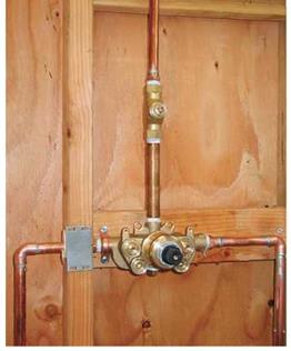
A shower wall at rough-in. A pressure-balancing antiscald valve (which mixes hot and cold water) is shown below. The smaller valve above is a volume control. Note the nail plates to protect the pipes and the stainless-steel screws, which will resist corrosion.


image613

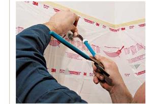
Finishing touches. To avoid marring the surface of a chrome shower arm, insert a sliding-jaw pliers handle into the pipe and turn it into final position. When the bathroom is painted and all brightware is installed, remove the protective plastic from the shower walls.


To avoid corrosion, use stainless-steel or brass bolts and nuts.


Tub Drain-and-Overflow Assembly


INSTALLING A TOILET

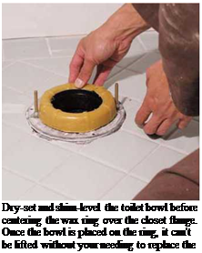
When you’re ready to install the toilet, remove the plastic bag you inserted earlier in the closet bend to block sewage gases. Place closet bolts in the closet flange if you haven’t already done so.

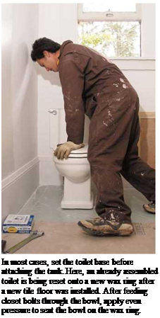
Set the bowl first. Then attach the tank to the bowl. If you’re re-installing an old toilet, as shown in the bottom left photo on p. 296, leave the parts connected, and set the toilet as one piece. But if it’s a new toilet, setting the base first is easier on your back. Place the wax ring in the closet flange, so that the ring’s plastic funnel centers in the flange. Some manufacturers rec­ommend placing the wax ring on the toilet horn and then inverting the toilet bowl, but the wax ring may not adhere and the funnel may not align.

Have help aligning closet bolts to holes as you set the toilet bowl. Don’t rock the bowl when set­ting it, which could excessively compress the wax ring on one side, creating a gap. Instead, press the bowl down evenly; then use a small adjustable wrench to tighten the nuts gradually, alternating sides, till the bowl is secure. Place a torpedo level atop the bowl edge to see if the unit is level side to side and front to back. If the bowl needs shimming, use plastic shims, which can be chiseled or cut flush to the toilet foot so they’re not visible. Don’t trim the closet bolts till you’ve attached the tank and tested the unit for leaks.

SETTING A PEDESTAL SINK


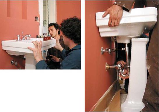
Check the sink for level one last time, tighten the lag screws to secure the sink, and connect the supply risers top and bottom.


It usually takes several tries and some fine-tuning to level the pedestal, level the sink in two directions, and then lag screw the sink to a 2x blocking let into the studs.


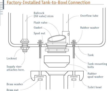
Mount the tank. Standard two-piece toilets have tanks that bolt directly to bowls. In addition to bolt holes, tanks have two fittings on the bottom: a threaded ballcock stem, which is screwed to the supply riser, and a larger flush valve, which is tightened to a spud nut. Typically, a rubber spud – nut washer covers the spud nut and cushions the tank-bowl juncture to prevent leaks; there may also be a separate, preinstalled sponge-rubber gasket to cushion the tank and bowl. Tighten the spud nut and position the spud-nut washer, insert the washered tank-mounting bolts into the bot­tom of the tank, and set the tank atop the bowl so that bolts line up with the holes in the bowl. Carefully follow the manufacturer’s instructions about caulking mating surfaces because some caulking compounds may deteriorate the gaskets.


Because the slot in the bank of the pedestal is narrow and the wall is close, there won’t be enough room to tighten slip-nut couplings on the drain. Instead, after starting the lag screws, lift and support the front of the sink while a helper slides the pedestal forward. After connecting the drain fittings, slide the pedestal back, and lower the sink.


End-Outlet Continuous Waste


11/4-ІП. ОГ

To prevent the tank-bolt threads from turning and cutting into the rubber washers or gaskets,

/

^—11/2-in. tailpieces _____

hold the bolts steady with a long screwdriver as you tighten the nuts on the underside of the bowl

/

Slip-nut trap adapter

shelf, using an adjustable wrench. Moving from

Sanitary tee —^


INSTALLING A TOILET
INSTALLING A TOILET

Save fixture invoices and shipping boxes till you’ve inspected fixtures for flaws. You’ll need both to return defective units. Apart from chipped enamel or cracks, the most common toilet flaws are a foot that is not flat, a deformed horn, or bowl and tank surfaces that don’t mate correctly.


Elbow


Total pipe length includes fitting sockets. P-trap


A common assembly for double sinks or lavatories.


image606image607

Подпись: INSTALLING A TOILETПодпись:Подпись:Подпись:image610

one side to the other, tighten the nuts snugly.

Use only brass or stainless-steel bolts and nuts. Connect the water supply, fill the tank, flush the toilet several times, and check for leaks. If there’s leaking between the tank and the bowl, tighten the nuts. If there’s leaking only near the foot of bowl, the wax ring may have failed: In this case, pull the toilet and replace the ring. If there are no leaks, trim the closet bolts and caulk around the perimeter of the foot.

Toilet supply connections are essentially the same as sink or lavatory risers. The standard toilet supply riser is 58-in. chrome tubing that attaches (at the top) to a threaded ballcock stem on the underside of the tank, and a 58 by 58 angle stop at the bottom. A better option is a 3з8-іп. flexi­ble braided stainless-steel supply line: It won’t crimp, attaches to the same fittings, and can be easily disconnected.

Bidets. A bidet is easier to install than a toilet. Although a bidet requires hot – and cold-water connections, its wastes are all liquid, so a 154-in. drain will suffice. Mount the bidet base securely, but it doesn’t need to be seated in a wax ring.

In fact, the drain takeoff is similar to that of a tub, which is described next.

Setting a Pedestal Sink

Installing a pedestal sink takes planning, a lot of adjusting, and two people. For starters, determine well in advance the height of the 2x blocking needed to anchor the sink, so you can cut that board into stud walls well before the drywall goes up.

Preattach the sink’s hardware before mount­ing it on the pedestal. Next, level the pedestal base, shimming it as needed. Ribbed plastic shims (also called ribbed stability wedges) work well for this task because their ribs keep them from slipping, even if it’s necessary to stack wedges on a badly out-of-level floor. Once the base is level, set the sink atop it and check it for level in two directions—front to back and side to side—using two torpedo levels, as shown in the left photo on p. 295. Chances are, you’ll need to reset the sink several times to get it level and stable because sinks and pedestals are often not perfectly mated.

Once you’re pleased with the sink’s placement, put a pencil in the back of the sink and mark the locations of the lag-screw holes onto the wall. Remove the sink, predrill the holes, start the lag screws, replace the sink, and check for level again. When the sink is level and the lag screws line up to the pilot holes, lift the sink slightly so a helper can slide out the pedestal, attach the drainpipes, slide back the pedestal and reset the sink, and finish tightening the washered lag screws. But don’t overtighten or you’ll crack the porcelain. Attach the supply risers top and bottom, test for leaks, and you’re done.

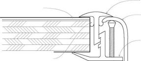
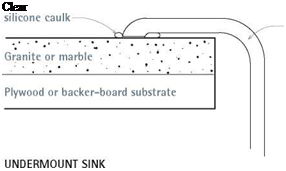
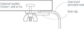
Подпись: I Sink-Mounting DetailsПодпись: For rimless and self-rimming sinks, first set the mounting device or sink edge in plumber's putty, which will compress.Подпись: RIMLESS SINKПодпись: Plastic laminateПодпись: Plumber's putty or caulkПодпись: Sink rim Sink lipПодпись: Rim clipimage603Подпись: Clear image605"Подпись: SELF-RIMMING SINK

those shown above. Wall-mounted models slip down into a bracket, which must be lag screwed to blocking attached to studs—preferably let into the stud edges. Level the sink front to back and side to side.

Connect the drain. With the sink or lav in place, connect the drainpipe. To the drain stub sticking out of the walls, glue a threaded male trap adapter, which will receive a slip coupling. Slide the trap arm into the coupling, but don’t tighten it yet. The other end of the trap arm turns down 90° and, being threaded, couples to an adjustable P-trap, which you can swivel so that it aligns to the tailpiece coming down from the lav. The other end of the P-trap has another slip coupling, into which the sink tailpiece fits. When trap
pieces are correctly aligned, tighten the slip couplings.

Kitchen sinks are much the same, except that the upper part of a sink tailpiece is threaded to tighten to the bottom of a strainer body. To drain double sinks, use the hookups shown in "End – Outlet Continuous Waste,” on the facing page. Back-to-back lavs or sinks can also share a com­mon drain, by using a figure-5 fitting (see the bottom photo on p. 277).

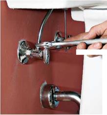
Connect supply pipes. To each supply pipe stub-out, attach a shutoff valve, typically an angle stop with a compression fitting. Slide the angle stop’s h-in. socket over the stub-out, and tighten the fitting so that the ferrule inside compresses and forms a positive seal. Alternatively, you can sweat /2-in. male threaded adapters onto the stub – outs, wrap Teflon tape on the threads, and screw on a shutoff valve with a h-in. threaded female opening.

Riser attachments depend on whether you install rigid chromed tubing, which inserts into a compression fitting on the angle stop, or a flexi­ble braided supply line, which has nuts on both ends. Rigid tubing must be shaped with a tubing bender and cut to exact length, whereas braided supply can be easily twisted or looped so it fits.