INSTALLING A BATHTUB
After framing the three-walled alcove around the tub, attaching 2×4 ledgers to support the tub lip, and cutting an opening in the subfloor for the drain assembly, dry-fit the tub and check for level in two directions. If the tub rocks after its lip is supported by the ledgers, remove the tub, apply 30-lb. building paper over the subfloor, and pour 1 in. to 2 in. of mortar. Place the tub in the mortar before it sets, so the mortar will conform to the shape of the tub. If the tub is made of cast- iron be sure to have at least three workers on hand to move it.
Drain and overflow assembly.
Before the final installation of the tub, preassemble the tub’s drain and overflow assembly and test-fit it to the tub openings. Slip-nut couplings make adjusting pipe lengths easy.
Once the tub back is in the alcove, install the assembly in the tub: Put a layer of plumber’s putty between any metal-to- enamel joint that isn’t gasketed.
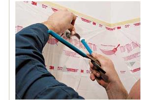
While a helper holds the assembly to the end and underside of the tub, hand screw the threaded strainer into the tub shoe (waste ell). Then use a strainer wrench
to tighten it solidly. The overflow plate inside the tub screws to a mounting flange in the overflow ell. There are many types of drain cap (stopper) mechanisms; follow the manufacturer’s instructions.
The last drain connection to be made is a P-trap, which slides onto the tub tailpiece descending from the tee. Adjust the trap so that it aligns with the branch drain roughed in earlier. Note: If the drain assembly will be inaccessible, code requires a glued-together drain joint. The only exception allowed is the slip-nut coupling that joins the tub tailpiece to the P-trap.
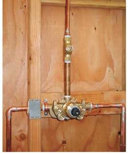
Water supply. Next, attach the tub’s supply pipes. Level and mount a pressure-balancing valve to the cross brace let into the end-wall studs.
(The valve, also called an antiscald valve, is typically set at a maximum of 120°F to prevent scalding.) Follow the manufacturer’s instructions for attaching the pipe to the valve. Although gate and ball valves are usually closed when sweating copper pipe to them, balancing valves may need to be open or disassembled before sweating pipe to the valve bodies.
Like most shower/tub valves, a balancing valve has four pipe connections: one each for hot – and cold-supply pipes, one for the pipe that runs to the shower arm, and one that services the spout. To mount shower arms and spouts, screw brass, threaded female drop-eared ells to the cross braces. Because chrome shower arms and spouts can get marred while finish surfaces are being installed, screw in 6-in. capped galvanized nipples. The faucet stem(s) and the balancing valve are protected with a plastic cover till the finish work is done. Turn the water on and test for leaks. Once you’re sure there are none, you are ready to close in the walls around the tub.
|
|
|
|
|
|
|
|
|
|
|


Leave a reply