Category RENOVATION 3

Copper Pipe: Disconnecting, Reconnecting, and Repairing

To disconnect a soldered fitting, apply heat till the solder melts. Then gently tap the fitting off the pipe. When the metal is cool, clean the pipe end, reflux, reheat, and solder on a new fitting. Unless the fitting is an expensive one, such as a gate valve, don’t reuse fittings that have already been soldered.

When disconnecting a fitting on an existing supply line, drain the pipe first; otherwise, the solder won’t melt. Draining and reconnecting will be much easier if the pipe section can be isolated with a shutoff valve, but sometimes old valves don’t shut perfectly. In that event, ball up a piece of white bread and stick it in the pipe to block the trickle while you solder. Once the water runs again, the bread will dissolve and flush out.

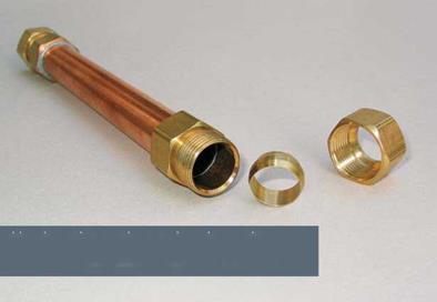
Finally, here’s a fix for split pipes that doesn’t require soldering at all: Cut out the damaged section of pipe and slide a compression repair coupling over the cut pipe ends. (The coupling’s inner diameter is the same as the Vl-in. rigid copper’s outer diameter.) Use a pair of adjustable wrenches to tighten the compression fittings on both ends of the coupling, and you’re done.

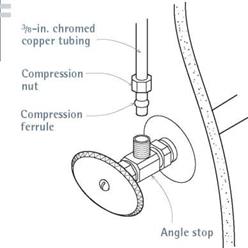
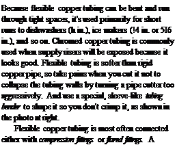
Подпись: When space is tight, presolder sections in a vise. Then, when placing the section in its final position, you'll have only a joint or two to solder. If one of the materials being joined might be damaged by heat, solder the copper parts first, allowing them to cool, before making mechanical connections to the heat-sensitive material. For example, if you need to connect copper supply to a pump outtake with plastic or adapters, solder the male (protruding) or female (receiving) adapter to the copper pipe before screwing it in (or on) the pump outtake. Finally, before soldering pipe to a ball valve or a gate valve, close the valve completely. Otherwise, solder can run inside and keep the valve from closing fully. However, when soldering a shower's pressure-balancing valve or a tempering valve, follow the manufacturer's instructions. Finally, it's helpful to have unions near most valves so that sections can be disconnected without needing to undo soldered joints. FLEXIBLE COPPER TUBING Подпись: Because flexible copper tubing can be bent and run through tight spaces, it's used primarily for short runs to dishwashers (h in.), ice makers (!4 in. or 5І6 in.), and so on. Chromed copper tubing is commonly used when supply risers will be exposed because it looks good. Flexible tubing is softer than rigid copper pipe, so take pains when you cut it not to collapse the tubing walls by turning a pipe cutter too aggressively. And use a special, sleeve-like tubing bender to shape it so you don't crimp it, as shown in the photo at right. Flexible copper tubing is most often connected either with compression fittings or flared fittings. A compression fitting features a ferrule of Подпись: I A Compression Fittingimage555Repairing pipes split by freezing water is no big deal with a compression repair coupling. Each end of the coupling compresses a brass ferrule to create a watertight seal without soldering.

image556

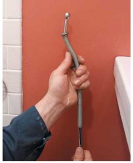
Use a tubing bender to shape chrome supply risers; the wire coils of the bender support the soft tubing and keep it from buckling as you gradually shape it.

soft metal that is compressed between a set of matched nuts. A flared fitting requires that you flare the tubing ends with a special tool. When using either type of connector, remember to slide nuts onto the tubing before attaching a ferrule or flaring an end. Both types of connection are easy to disconnect, and so are used where repairs may be expected, such as the supply line to a toilet. Don’t reuse ferrules, however; replace them if you need to disconnect fittings.

In most situations, braided stainless-steel sup­ply lines are a better choice than flexible copper tubing: Braided lines are strong, look good, and can be connected and disconnected as often as needed.

GALVANIZED STEEL PIPE

Galvanized pipe corrodes and constricts, re­ducing flow and water pressure, so it is no longer installed as water-supply pipe. If your existing system is galvanized and the water flow is weak, replace it as soon as possible. If you’re not quite ready to rip out and replace all of your galva­nized pipe, you can replace or extend sections with rigid copper. However, you must use a dielectric union (see the photo on p. 272) to join copper sections to steel. Otherwise, electrolysis will take place between the two metals, and cor­rosion will accelerate.

Today, galvanized pipe is largely limited to gas-supply service. Because of safety considera­tions and the difficulty of threading pipe without a power threader, have a licensed plumber install gas-supply service pipes. A plumber will install gas shutoff valves to gas-supply stubs; short lengths of flexible gas-supply pipe run from there to a fix­ture.

CPVC SUPPLY

Most plumbing codes allow CPVC for hot – and cold-water applications, but check with local authorities to be sure. CPVC is a good choice for hard-water areas, because—unlike copper— CPVC won’t be corroded by chemicals in the water. Note: CPVC is a different material from PVC, which is widely used as drain and waste pipe; PVC may not be used as supply pipe, how­ever, because it releases carcinogens.

That noted, working with CPVC supply pipe is much like cutting and joining plastic DWV pipes, explained at some length later in this chapter.

The main difference is that waste pipes are larger. Briefly, here’s how to join CPVC: Cut the pipe ends square using a plastic-pipe saw or plastic – pipe cutting shears. Clean the pipe ends as well as the inside of the fitting. Next, apply solvent – based cement to each. Insert the pipe into the fitting, turning either the pipe or the fitting a quarter turn in one direction only to spread the cement. Finally, allow the glued joints to set ade­quately before putting pressure on the line.

Before installing CPVC, make sure that you have the adapters needed to join the new plastic pipes to existing metal pipes and fixtures.

Measuring and Fitting Pipe

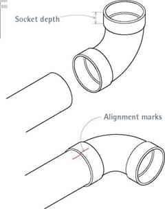
When measuring water-supply or dwv pipe runs, keep in mind that most pipe slides into fitting sockets. The depth of the socket is its seating distance (seating depth), which you must add to the face-to-face measurements between pipe fittings. When running pipe between copper fittings with a seating depth of VI in., for example, add 1 in. to the overall measurement. Rigid 3/4-in. copper fittings have a 3/4-in. seating depth.

As important, after you dry-fit pipes so fit­tings point in the correct direction, use a grease pencil or a builder’s crayon to create alignment marks on the pipes and fittings. That way you’ll be sure the fittings are pointing in the right direction when you make the final connections. Alignment marks are particularly important when cementing plastic pipe because you must turn plastic pipes one-quarter turn after inserting them into fittings; the marks tell you when to stop turning.

Socket Depths of ABS/PVC Fittings*

SOCKET

SOCKET

DIAMETER (in.)

DEPTH (in.)

IV2

3/4

2

7/S

3

V/2

* Fitting sockets vary, always measure depth to be sure.

threaded end. A sweat/female adapter has a threaded receiving end. Adaptors are also called transition fittings because they allow a transition in joining, as just described, or a transition in pipe materials. A dielectric union can join galva­nized and copper, without the electrolytic corro­sion that usually occurs when you join dissimilar metals.

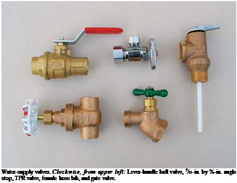
Valves are specialized fittings with moving parts. Gate valves are the most common type of shutoff valve, although lever-handled ball valves are gaining popularity because they are easier to operate. Hose bibs have a threaded outlet that you can screw a garden hose to. Angle stops are shutoff valves that control water flow to lavatories, sinks, bidets, and toilets. TPR (temperature – and pressure-relief) valves are spring-loaded safety valves that keep water heaters from exploding should the water get too hot or the tank pressure too great.

WORKING WITH COPPER SUPPLY PIPE

Type M rigid copper is the most commonly used copper supply pipe in houses, although type L, which is thicker, may also be specified. Type K, the thickest of the three, is usually specified for commercial and industrial jobs.

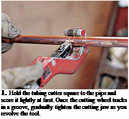
To cut rigid copper, place a tubing cutter on the pipe, so that its cutting wheel is perpendicular to the pipe. Score the pipe lightly at first, till the cut­ting wheel tracks in a groove. Gradually tighten the cutting jaw as you rotate the tool, until you cut through. If you tighten the tool too aggressively, you will flatten the pipe or score erratically, thus creating a weak joint.

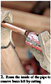
When the cut is complete, clean the end of the pipe with the deburring attachment on the cutter so that you get a good, solid joint. Leftover burrs also increase turbulence and thus decrease flow through the pipe. Use plumber’s sand cloth or

I Pipe Fitting

image548

When measuring pipe, allow for socket depths. Also when dry-fitting pipe assemblies, draw alignment marks on pipes and fittings to help you point the fittings in the right direction when assembled. This is particularly helpful when giving plastic fittings one – quarter turn after glue is applied.

emery paper to polish both ends of the pipe, and a round wire brush to clean the insides of fittings.

To solder copper pipe, first use a flux brush to apply self-tinning flux (soldering paste) to the outside of the pipe and the inside of the fitting. Then slide the fitting over the pipe. If the fitting is a directional fitting, such as a tee or an elbow, make sure that the fitting points in the correct direction.

Heat the fitting (not the pipe), moving the sol­dering torch so that all sides of the fitting receive heat directly. The flux will bubble. From time to time, remove the torch, and touch solder to the fitting seam. When the fitting is hot enough, the solder will liquefy when touched to it. After a few trials, you’ll know when a fitting is hot enough. When the fitting is hot, some fluxes change color, from milky brown to dull silver.

Подпись: CUTTING AND SOLDERING COPPER

Подпись: 1. Hold the tubing cutter square to the pipe and score it lightly at first. Once the cutting wheel tracks in a groove, gradually tighten the cutting jaw as you revolve the tool.

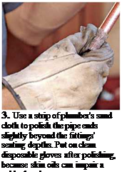
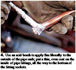
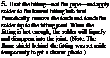
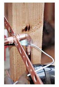
Подпись:Подпись: 3. Use a strip of plumber's sand cloth to polish the pipe ends slightly beyond the fittings' seating depths. Put on clean disposable gloves after polishing, because skin oils can impair a solder bond. Подпись: 4. Use an acid brush to apply flux liberally to the outside of the pipe ends; put a thin, even coat on the inside of pipe fittings, all the way to the bottom of the fitting sockets. Подпись: 5. Heat the fitting—not the pipe—and apply solder to the lowest fitting hub first. Periodically remove the torch and touch the solder tip to the fitting joint. When the fitting is hot enough, the solder will liquefy and disappear into the joint. (Note: The flame shield behind the fitting was set aside temporarily to get a clearer photo.)image553Подпись: SAFETY ALERT Check the solder label to make sure it is lead free. Though lead has long been known to be a neurotoxin, plumbers continued to use 50:50 (half-lead) solder till it was banned in 1986. Modern solders are typically tin-antimony, tin-silver, or tin- copper-silver alloys. llllll Two passes with the solder, completely around the joint, will make a tight seal; more than two passes is a waste. The solder is sucked into the joint, so don’t worry if you don’t see a thick fillet of solder around the joint. Let solder cool before putting pressure on a joint. After a soldered joint

Подпись: Quality solder, such as a silver alloy, is easier to work with than standard 95/5 solder: You'll have a wider working temperature range, better void filling, and fewer leaks. Quality solder can cost 50 percent more than standard types, but it's worth it. 1111 image554has cooled for a minute, you can immerse it in water to cool it completely; but be careful when handling hot metal.

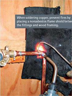
Soldering in tight spaces can’t always be avoided. If a fitting has several incoming pipes— at a tee, for example—try to solder all pipes at the same time. That is, reheating a fitting to add pipes will weaken earlier soldered joints. Clean and flux the pipes, insert them in the fitting, and keep the torch moving so you heat both ends of the fitting equally. If you must reheat a fitting to add a pipe later, wrap the already soldered joint in wet rags to keep its solder from melting. When soldering close to wood, wet the wood first with a plant spritzer filled with water and then use a flame shield to avoid scorching or igniting it.

Working with Copper Water-Supply Pipe

This section focuses on installing rigid copper water pipe: It’s strong, easily worked, approved by virtually all codes, and represents nearly 90 percent of residential installations. That noted, you should also consider reading about PEX flexible tubing on p. 279.

Fittings

If you divide fittings into a few categories, their many names start to make sense. Because they do similar things, supply-pipe and DWV fittings often share names.

Fittings join pipes. The simplest fitting is a cou­pling, which joins two straight lengths of pipe. A reducing coupling joins different size pipes. A repair coupling has no internal stop midway, so it can slide all the way onto a pipe, then slide back over a new piece of pipe inserted to repair a dam­aged section. A union is a coupling you can disconnect.

Fittings change direction. The most common directional fitting is a 90°elbow, also known sim­ply as a 90 or an ell. For a more gradual turn, use a 45°elbow, also called a 45 or a Vs bend. A street ell is a 90° elbow with one hubless end, which can fit directly into another fitting’s hub. Ditto, a street 45.

Tees join three pipes. Tees (also spelled T’s) allow you to run branch pipes to individual fix­tures or fixture groups. Reducing tees accept dif­ferent size pipes. If you want to sound like a pro, "read a tee” by noting its run (length) dimension first (in inches), then its branch leg. If both ends of the run are the same size, mention that num­ber only once, as in % by h. But if two legs of a tee reduce, cite all three of the tee’s dimensions, for example: a % by h by h.

Adapters join different types of pipe. A

sweat/male adapter has a soldered end and a

Plumbing Safety

► Get a work permit and a copy of current plumbing codes from your local building depart­ment. Follow the codes closely; they’re there

to protect you.

► Get a tetanus shot before you start, and dress for dirty work.

► Wear protective eyewear when using power tools, chiseling, soldering, and striking with hammers—in short, for most plumbing tasks. Wear heavy gloves when handling drainpipe and dispos­able plastic gloves when working with solvent – based cements or soldering. Wear a respirator mask (not a mere dust mask) when soldering or working around existing soil pipes; P100 filters are the standard protection.

► Use only cordless power tools when cutting into supply pipe. If a power tool shorts out in that situation, it could be fatal. О Before cutting into finish surfaces, shut off the electrical power to nearby outlets, and test with a voltage tester,

as shown on p.235, to be sure power is really off.

► Ensure good ventilation when joining pipes because heated solder and solvent-based cements give off noxious fumes. Make sure you have adequate lighting.

► When soldering joints in place, place a nonasbestos flame shield behind the fittings to avoid igniting the wood framing. Have a plant spritzer, filled with water, on hand to dampen the wood if you must solder fittings close to framing; make sure there’s a fire extinguisher on site.

Molten flux or solder can burn you, so be careful.

► When connecting to existing DWV pipes, plan the task carefully. Flush pipes with clean water beforehand and have parts ready so that you can close things up as soon as possible. To avoid weakening nearby joints, be sure to support pipes before cutting them.

► Be fastidious about washing well after han­dling contaminated waste pipes and chemicals.

► If you smell gas in a home, stop working: Running equipment or doing soldering could spark an explosion. If you can quickly locate the gas shutoff valve outside, shut it off. In any event, clear everyone from the house at once and call the local gas utility.

image546

Подпись:Подпись: TIPПодпись:

Planning

If you’ll be adding or moving fixtures, you’ll need to install pipes, and that will require permits and planning. Start by assessing the condition of existing pipes (see Chapter 1), which you can connect to if they are in good shape. Create a scale drawing of proposed changes, assemble a materials list, and then ask a plumbing-supply store clerk or a plumber to review both. If you’re well organized, clerks at supply stores will usually be glad to help. However, if you need help understanding your existing system, hire a plumber to assess your system. He or she can also explain how to apply for a permit and which inspections will be required.

IS THERE ENOUGH ROOM?

If you’re adding a bathroom, first consider the overall size of the room. If there’s not enough space, you may need to move walls. Layouts with pipes located in one wall are usually the least dis­ruptive and most economical because pipes can be lined up in one plane. On the other hand, lay­outs with pipes in three walls are rarely sensible or feasible unless there’s unfinished space above or below in which to run pipes.

FIXTURE ROUGH-IN DIMENSIONS

Once you have a general idea if there’s enough room, focus on the code requirements for each fixture, which dictate where fixtures and pipes

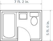
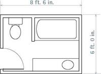
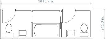
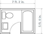
I Minimum Bathroom Dimensions

PIPES IN TWO WALLS

PIPES IN ONE WALL

image533


PIPES IN THREE WALLS

image535


FIVE FIXTURES

image536


image534

must go. It would be aggravating and expensive if code inspectors insisted that you move fixtures after finish floors and walls had been put in place. So install fixtures and pipes to conform with code minimums. The drawings on these two pages show typical drainpipe and supply pipe centers for each fixture and, in most cases, mini­mum clearances required from walls, cabinets, and the like.

On toilets, the horn—the integral porcelain bell protruding from the bottom—centers in the floor flange. The flange, and the closet bend to which it attaches, should be centered 12 in. from the finish wall for most toilets or 1212 in. from an exposed stud wall. Codes require at least 15 in. clearance from the center of the toilet to walls or cabinets on both sides: In order words, install toilets in a space at least 30-in. wide. There must also be at least 24 in. clear space in front of the toilet.

Toilets with 10-in. and 14-in. rough-in dimen­sions are available to resolve thorny layout issues (such as an immovable beam underneath) or to replace nonstandard toilets. For example, if you replace a wall-hung toilet with a standard

Toilet

I Rough-In Dimensions

image537

Center the toilet drain 12 in. from the finished wall behind the unit. Allow at least 15 in. of clearance on both sides of the toilet, measured from the center of the drain.

(close-coupled) unit, there would be an ugly 2-in. gap between the toilet and the finish wall. By installing a 14-in. rough toilet, whose base is longer, you can use the existing floor flange and eliminate the gap behind the toilet.

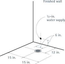
Install water-supply risers on the wall behind the toilet, 6 in. above the floor and 6 in. to the left of the drainpipe. If there’s a functional riser stick­ing out of the floor, use it. But floor risers are sel­dom installed today because they make mopping the floor difficult. Clearances around bidets are the same as those for toilets.

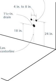
Lavatories and pedestal sinks should be a comfortable height for users. Typically, lavatory rims are set 32 in. to 34. in. above the finish floor; but if a family is tall, raise the lav. (But if you do, remember to raise drain and supply pipe holes an equal amount.) Codes require at least 18 in. clearance in front of a sink; 24 in. is better.

Lavatory drains are typically 18 in. above the floor and centered under the lavatory, although adjustable P-traps afford some flexibility in positioning drains. Center supply pipes under the lav, 24 in. above the floor, with holes spaced 4 in. on center. Pedestal sink drains are housed in the pedestal, so tolerances are tight; follow the manufacturer’s installation instructions when positioning pipes.

Bathtubs and showers vary greatly, so follow the manufacturer’s guides when positioning the pipes. Most standard tubs are 30 in. to 32 in. wide and 5 ft. to 6 ft. long. Codes require a mini­mum of 18 in. clearance along a tub’s open side(s); 24 in. is better.

Freestanding tubs have exposed drain and overflow assemblies, so their 112-in. drains can be easily positioned to avoid joists and other design constraints. Standard tubs require a hole approx­imately 12 in. by 12 in. cut into the subfloor under the tub drain end, to accommodate the drain and overflow assembly. If an existing joist is in the path of the tub drain, you may need to cut through the joist and add doubled headers, as explained further on p. 287.

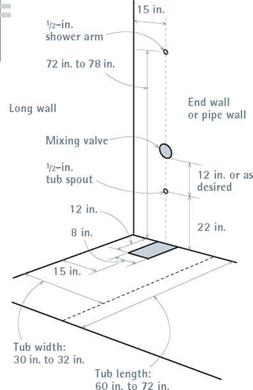
Positioning supply pipes and valve stems is easier because they’re smaller and typically centered on an end wall—although, again, follow the manufacturer’s rough-in dimensions for code-required pressure-balancing valves and the like. Place the shower arm 72 in. to 78 in. above the floor so taller users won’t need to stoop when taking a shower. Place the tub spout 22 in. high. Tub faucet handles (and mixing valves) are cus­tomarily 6 in. above the spout.

1/2-ІП.

water supply

image538

Подпись: Lavatory Rough-In Dimensions
Подпись: Kitchen Sink Rough-In Dimensions

Tub/Shower Rough-In Dimensions

image539

The tub drain and stubs in the end wall should be centered 15 in. from the long wall. Mixing valves are typically set 12 in. above the tub spout, whereas individual valve stems are set 6 in. above the spout, 8 in. o. c., or follow the manufacturer’s recommended rough-in specs.

image540

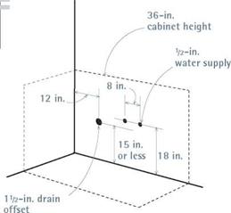
Double sinks are most often installed in kitchens, so the drain is often offset under one sink, as shown in the drawing on p. 295. Braided stainless-steel supply lines are very flexible, so you can rough-in water supply stub-outs at any convenient height; 18 in. is common.

Kitchen sinks frequently have double basins, so you can center or offset drainpipes. In standard 36-in.-wide base cabinet, the drain is often offset so that it is 12 in. from one cabinet sidewall, leav­ing room to hook up a garbage disposer. To make cabinet installation easier, have the drain exit into the wall rather than the floor. A drain that exits 15 in. above the finish floor will accommo­date the height of a garbage disposal (11 in.) and the average depth (9 in.) of a kitchen sink. Sink faucet holes are typically spaced 8 in. on center, so align supply pipes with their centerline, roughly 2 in. above the drain height. Supply-pipe height is not critical because risers easily accommodate varying heights.

SKETCHING LAYOUTS

Make a separate sketch of each floor’s plumbing; include the basement and attic, too. The easiest way to do this to create an accurate outline of the house’s footprint, using graph paper and a scale of /a in. per 1 ft. Then use tracing-paper overlays for each floor’s plumbing layout. Indicate existing fixtures, drains, supply pipes, water-using appli­ances, and the water heater. Where pipes are exposed, note the size and dimension of drains and stacks and where the supply pipes exit into
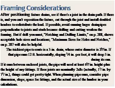
Подпись: Framing Considerations After positioning fixture drains, see if there's a joist in the drain path. If there is, and you can't reposition the fixture, cut through the joist and install doubled headers to redistribute the load. If possible, avoid running larger drainpipes perpendicular to joists and studs because drilling and cutting weaken the framing. But if drill you must, "Notching and Drilling Limits," on p. 288, shows acceptable hole sizes and locations; "Maximum Sizes for Holes and Notches," on p. 287 will also be helpful. The trickiest pipe to route is a 3-in. drain, whose outer diameter is З1/? in. If that pipe runs 12 ft. horizontally, sloping 1/4 in. per foot, it will drop 3 in. during its run. If it runs between enclosed joists, the pipe will need at least б1/? in. height-plus the height of any fittings. If floor joists are nominally 2x8s (actually, 11/ in. by 71/ in.), things could get pretty tight. When planning pipe runs, consider pipe dimension, slope, space for fittings, and the actual size of the lumber in your calculations. image541

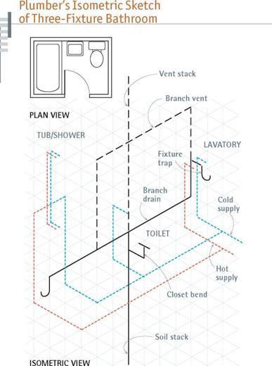
Try to obtain sheets of plumber’s isometric paper so you can show bathroom rough-ins in three dimensions. Art or engineering supply stores may carry the paper, but the Internet is probably a better bet.

the floor above. Especially note the location of 3-in. main drains and vents: If you can cluster fixtures around larger DWV pipes within a room—or from floor to floor—you’ll shorten the distance that fixture drains must travel and thus reduce the amount of framing you may have to cut or drill when running the new pipes.

If you’re moving or adding fixtures, make separate floor sketches for them, too. By laying tracing-paper sketches of old and new plumbing atop each other, you can quickly see if fixtures cluster and, if you’re adding fixtures to an exist­ing system, the closest part of a drain or supply pipe to connect to and extend from. Plumbers use isometric paper to draw pipe runs, as shown in "Plumber’s Isometric Sketch of a Three-Fixture Bathroom,” at left, but any to-scale sketch will give you an approximate idea how long pipe runs will be. Sketches also tell you where you’ll need fittings because the pipes change direction, con­nect to branches, or decrease in size.

Tools

With a modest tool collection, you’ll be ready for most plumbing tasks.

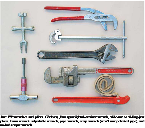
Pipe wrenches tighten and loosen threaded metal joints, such as %-in. nipples (short pipe lengths) screwed into a water heater, galvanized pipe unions, and so on. A pair of 10-in. or 12-in. pipe wrenches should handle most tasks. Get two: Most of the time, you’ll need one wrench to hold the pipe and the other to turn the fitting.

Adjustable wrenches (also called Crescent wrenches) have smooth jaws that grip but won’t mar chrome nuts and faucet trim. Get several:

A 4-in. adjustable wrench is right for the closet bolts that anchor toilet bowls, a 12-in. wrench gives extra leverage for stubborn nuts, and an 8-in. wrench is appropriate for almost every­thing else.

Strap wrenches aren’t a must-have tool but are useful when you need to grip polished pipe without scarring it.

Slide-nut (sliding-jaw) pliers are good utility tools for holding nuts, loosening pipe stubs, and holding a pipe section while it’s being soldered.

The jaws of locking pliers (or Vise-Grip pliers) adjust and clamp down on fittings, for example, so you can have both hands free to hold a torch and apply solder.

Basin wrenches are about the only tools that can reach water-supply nuts on the underside of sinks and lavs, where supply pipes attach to threaded faucet stems.

Tub-strainer wrenches tighten tub strainer and tailpiece assemblies.

No-hub torque wrenches tighten stainless – steel band clamps on no-hub couplings. Many
Подпись:

plumbers use a cordless drill/driver to do most of the tightening, but code requires that final tight­ening be done by hand.

Pipe cutters (also called wheeled tubing cut­ters) are the best tools for a clean, square cut on copper pipe. Tighten the cutter so that its cutting wheel barely scores the pipe; then rotate the tool around the pipe, gradually tightening until the cut is complete. Many types have a foldaway deburring tool. Use a close-quarters cutter (thumb cutter) where there’s no room for a full-size one. If you’re installing CPVC plastic supply pipe, use tubing shears for clean, quick cuts. A hacksaw works, but not as well.

A reaming tool (if your cutter doesn’t have one attached) is used to clean metal burrs after cutting copper. Use a round wire brush to polish the inside of copper fittings after reaming and plumber’s sand cloth to polish the pipe ends.

If you’re cutting plastic pipe, use a rounded file to remove burrs—the steel jaws of an adjustable wrench also work well for deburring plastic pipe.

Wide-roll pipe cutters open wide to receive the larger diameters of plastic DWV pipe. Plastic-pipe saws have fine teeth that cut ABS and PVC pipe cleanly—and squarely, if used with a miter box. If you need to cut into cast iron, rent a snap cutter, also known as a cast-iron cutter. It’s the only tool that cuts cast iron easily. Some models have ratchet heads for working in confined places.

A cordless drill and cordless reciprocating saws are must-haves if you’re working around metal pipes that could become energized by electricity and when working in tight, often damp crawl spaces. Old lumber can be hard stuff to drill or cut, so 14.4-volt cordless tools are minimal. Cord­
less drills are perfect for attaching plumber’s strap, drilling holes in laminate countertops, and so on.

If you need to drill 2-in. (or bigger) holes, use a corded drill. Heavy-duty drilling takes sustained power and more torque than most cordless drills have. A 12-in. right-angle drill supplies the muscle you need in close quarters.
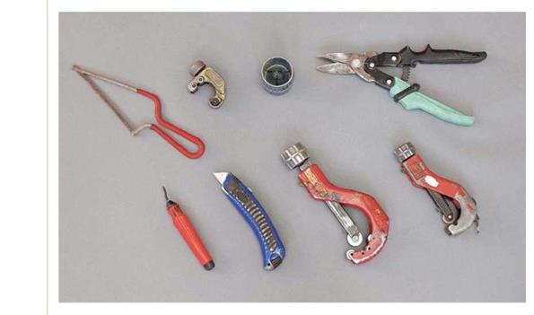
image543Cutting and reaming tools. Top row, from left:miniature hacksaw, close – quarters cutter, combo chamfer and reamer (cleans burrs from pipe ends after cutting), and aviation snips. Bottom row:reamer, utility knife, large-wheeled tubing cutter (cuts up to 2-in. plastic pipe), and wheeled tubing cutter. The cutting wheels can be changed for different pipe materials.

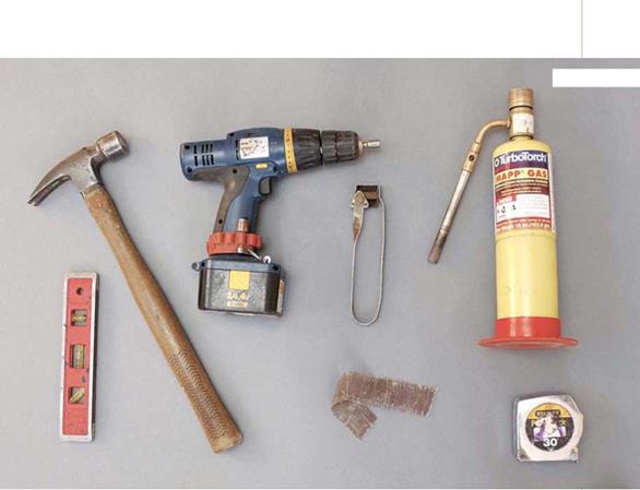
Miscellaneous tools. Clockwise, from left:torpedo level, hammer, 14.4-volt cordless drill, flint and steel striker (lights torch), MAPP gas soldering torch, tape measure, and plumber’s sand cloth (used before fluxing pipe).


image544

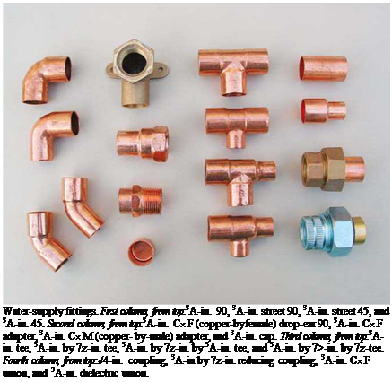
Подпись: Water-supply fittings. First column, from top:3A-in. 90, 3A-in. street 90, 3A-in. street 45, and 3A-in. 45. Second column, from top:3A-in. Cx F (copper-byfemale) drop-ear 90, 3A-in. Cx F adapter, 3A-in. Cx M (copper- by-male) adapter, and 3A-in. cap. Third column, from top:3A-in. tee, 3A-in. by 7z-in. tee, 3A-in. by 7z-in. by 3A-in. tee, and 3A-in. by 7>-in. by 7z-tee. Fourth column, from top:з/4-in. coupling, 3A-in by 7z-in. reducing coupling, 3A-in. Cx F union, and 3A-in. dielectric union.

MAPP (methylacetylene propadiene) gas torches have generally replaced propane units (once popular with do-it-yourselfers) and even larger professional rigs with tanks, hoses, and fancy nozzles. MAPP gas torches are perfect for soldering the ’/2-in. or %-in. fittings encountered most often in house plumbing.

Nonasbestos flame shields protect wood fram­ing when soldering joints. It is also important to have a fire extinguisher nearby.

Your plumbing kit should also include a hand­ful of other tools. Aviation snips are used for cutting perforated strap and trimming gaskets, and a torpedo level helps with leveling stub-outs (pipe stubs protruding into a room), sinks, and toilet bowls. You’ll also want a hacksaw, screwdriver with interchangeable magnetic bits, utility knife, and hammer.
An Overview of Plumbing Systems

A plumbing system is a loop of sorts, created by supply (or delivery) pipes that carry potable water to the house and its fixtures and by drainage, waste, and venting (DWV) pipes that carry waste water, effluvia, and sewage gases away from the fixtures—sinks, toilets, lavatories, washing machines, and so on.

These two systems within a system are quite different from each other. DWV pipes are larger and must slope downward so wastes can fall freely (by gravity) and sewage gases can rise through vents. Consequently, large DWV pipes can be difficult to route through framing. By con­trast, smaller water-supply pipes are easy to run through studs and joists, and they deliver water under pressure, so there’s no need to slope them.

THE WATER SUPPLY

The pipe that delivers water to a house (from a city water main or an individual well) is called the service pipe. So it won’t freeze, a service pipe must run below the frost line and enter a building through its foundation. Typically, a 1-in. service pipe is controlled by a main shutoff valve shortly after it enters a building; but municipal hookups may enter a water meter first. Plumbing codes may also require a pressure-reducing valve if water pressure is more than 80 psi (pounds per square inch).

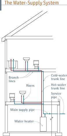
On the other side of the shutoff valve, the serv­ice pipe continues as the main supply pipe, com­monly % in. in diameter. At some point, the main supply pipe enters a tee fitting, at which point it splits, with one leg continuing on as a cold-water trunk line and the other feeding into the water heater, where it emerges as the hot-water trunk line. From the 14-in. hot and cold trunks run vari­ous /2-in. branch lines that serve fixture groups. Finally, individual risers (supply tubes) run from branch lines to fixtures. Risers are % in. or 12 in. in diameter and connect to fixtures with threaded fittings. By decreasing in diameter as they get farther from the trunk lines, supply pipes help maintain constant water pressure.

Before the 1950s, supply pipes were usually galvanized steel, joined by threaded fixtures, but steel pipes corrode and corrosion constricts flow. Consequently, rigid copper piping, which cor­rodes more slowly, soon replaced galvanized. Joined by soldering (sweat fitting), copper was also easier to install and has been the dominant supply piping since the 1950s. Rigid plastic pipe, especially CPVC (chlorinated polyvinyl chloride), has gained market share because it is corrosion

image530

Originating at a service pipe from the street (or from a well), the main supply pipe splits at a T-fitting, with one leg feeding cold-water trunk lines and the other entering the water heater to emerge as the hot-water trunk line.

resistant, less expensive than copper, and easily assembled with solvent cement. But it may be PEX (cross-linked polyethylene) flexible piping that will finally dethrone King Copper (PEX is discussed later in this chapter).

DRAINAGE, WASTE, AND VENTING

The DWV system carries wastes and sewage gases away from the house.

► Every fixture has a drain trap designed to remain filled with water after the fixture empties. This residual water keeps sewage gases from rising into living spaces. (Toilets have integral traps.) As trap arms leave individual fixtures, they empty into branch drains or directly into a soil stack, which, at its base, turns and becomes the main drain. The main drain then discharges into a city sewer main or a septic tank.

Подпись: PROTIP If you're new to plumbing and need help, learn the lingo and get to know the staff at a local plumbing-supply store. But visit the store during off-peak hours. The last thing counter clerks need during the 8 a.m. rush is duffers with dinky orders and a million questions. When business is slow, however, most of these clerks are happy to share what they know. 1111 Drainpipes may also be differentiated according to the wastes they carry: soil pipes and soil stacks carry fecal matter and urine, whereas waste pipes carry waste water but not soil. Stacks are vertical pipes, although they may jog slightly to avoid obstacles.
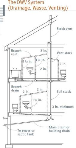
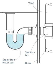
► Venting is the Fin DWV. Without venting, wastes would either not fall at all or, in falling, would suck the water out of fixture traps, allowing sewage gases to enter living spaces. Vents admit an amount of air equal to that displaced by the falling water. Thus every fixture must be vented. In most cases, the trap arm exits into a tee fitting whose bottom leg is a branch drain and whose upper leg is a branch vent. Branch vents continue upward, often joining other fixture vents, until they join a vent stack, which exits through the roof.

image531

Drainpipes must slope downward at least ‘/4 in. per foot so wastes can fall freely. Vent pipes must slope upward at least ‘/8 in. per foot so sewage gases can rise and exit the building.

Because vents must admit enough air to offset that displaced by falling water, vents are approxi­mately the same size as their companion drains. Branch vents and drains are usually 112-in. or 2-in. pipes, and main stacks and drains are 3 in. Minimums are indicated in "Minimum Drain, Trap, and Vent Sizes,” on p. 281. Important: Drainpipes must slope downward at least ‘/a in. per foot so that wastes will be carried out; vent pipes usually slope upward a minimun of 18 in. per foot.

DWV pipes may be of any number of materi­als. Thus an older house may have drain and vent pipes with sections of cast iron, galvanized steel, copper, or plastic. Because some of these materi­als are also used for supply, let size be your guide: If an existing pipe’s diameter is 114 in. to 4 in., it’s a drain or vent pipe. DWV pipes installed these days are mostly plastic: white PVC (polyvinyl chloride) or black ABS (acrylonitrile butadiene styrene). Fortunately, there is a host of ingenious fittings that enable you to tightly connect these various materials, should you need to. Note: If sound suppression is an issue, you should insu­late plastic pipes or install cast iron.

I A Drain Trap

image532

Water traps seal sewage gases from living spaces, but they need vents to operate properly. Without incoming air from the vent, falling wastes could suck the water out of traps.

Plumbing

Подпись: щПодпись: other Nature knows a thing or two about plumbing. larger midrib of this leaf is a naturally occurring trunk line, with smaller veins branching off to supply the leaf.image528

image529

Builders have benefited greatly from

the standardization of building materials, and nowhere is this more true than in plumbing. Whereas a plumber once had to fashion waste systems from cast iron, oakum, and melted lead, today one needs little more than plastic pipe and solvent-based cement. Such improved technology enables more people to understand, repair, and install plumbing. Would-be plumbers should do two things:

► Learn the vocabulary. Some people feel intimidated by the plethora of plumbing terms, especially fitting names. But there’s actually a logic to all those names, once you learn what a part does and why it is shaped as it is. Besides, you’ll get better service from plumbing-supply clerks if you can speak their language.

► Consult local plumbing codes before beginning a project. Codes protect your health and that of your neighbors. They spell out when you need permits, what materials you may use, and at what stages the work must be inspected. There is no national code, so most local building departments often follow the Uniform Plumbing Code (UPC) or the Inter­national Residential Code (IRC). Get a copy of local plumbing codes from your building department.

Recommended further reading: Merle Henkenius’s Plumbing (Creative Homeowner) and two books by Peter Hemp, Installing and Repairing Plumbing Fixtures and Plumbing a House (both The Taunton Press).

Local plumbing codes vary greatly. In general, you don’t need a permit if you replace a fixture, such as a sink, toilet, or washing machine, with­out changing existing pipes. However, if you want to add new fixtures or move existing ones, you’ll need a permit because you’ll need to change pipes.

Replacing a water heater also requires a permit —even if you connect to existing pipes. Here, the issue is safety: Inspectors want to make sure that gas – and oil-fired water heaters are properly vented and that electric heaters are correctly wired. They’ll also check that temperature – and pressure – relief (TPR) valves, which keep water heaters from exploding, are correctly rated and installed.

Adding Outdoor Receptacles

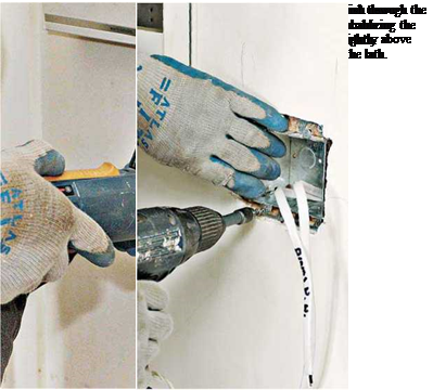
© To add an outdoor receptacle, find the nearest wall cavity that contains a general-use or lighting circuit, turn off the power, discon­nect the receptacle, and fish wire to the new outdoor outlet. However, do not tap into kitchen or bathroom circuits or circuits dedicated to a single appliance. To position the outdoor box, use a utility knife to cut back drywall 2 in. on one side of the existing box; then push aside the insulation in the wall and drill a %-in. hole through the sheathing and the siding. Note any­thing in the wall that would obstruct a new box. If you can’t find a good spot, caulk the hole with urethane, and try another location.

Trace the back of the new outlet box onto a flat section of siding. Then use a reciprocating saw to cut out the siding and—depending on the type of weather-tight box you install— sheathing within that outline. All outdoor receptacles must be GFCIs, housed in "water­proof while in-use" covers. Feed cable into a clamp at the back of the box (12 in. of cable should stick out of the new box), tighten the cable clamp, mount the weatherproof box, and caulk around its perimeter with silicone or urethane caulk.

Wire an outdoor GFCI receptacle as you would an interior one. After screwing the wired receptacle to the new box, attach the gasket and the waterproof cover, splice the new cable to the existing one, and reconnect the indoor recepta­cle. Turn the power back on, and then test both receptacles to be sure they’re correctly wired.

Then use a drywall circle cutter to cut it out. (If you must use a utility knife, the fixture’s trim col­lar will cover up a less-than-perfect hole.)

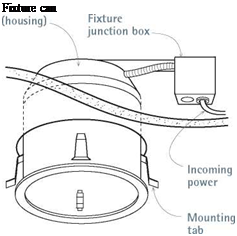
Open the fixture’s junction box. Then strip and splice incoming cable wires to the wires inside the junction box, using the twist-on wire nuts provided. Connections are standard: black wires to black, white wires to white, ground wire to green screw. Close the junction box and feed it through the hole in the ceiling first. Then insert the fixture can into the opening and rotate it till its spring mounting clips engage the ceiling. Insert the fixture’s inner baffle, whose mounting springs fit into slots inside the can. Install a light – bulb and the unit’s trim collar. Then turn the power on to test.

Mounting heavier fixtures is easier if there’s an unfinished attic above. In this case, simply drill an exploratory hole through the ceiling to approximate the desired fixture location. Then go up in the attic and decide whether it’s easier to nail a ceiling box to the nearest joist or to run a bar-hanger box between the joists and mount a ceiling box to it. Bar-hanger boxes allow you to position fixtures exactly where you want them, because you can slide the box along the bar. That decided, from the attic, cut out an opening for the ceiling box, which is almost always round.

Use a drywall circle cutter for drywall, a cordless jigsaw for plaster.

There are dozens of types of ceiling boxes, from flat 4-in. pancake boxes that screw to the edges of joists to deeper nail-in boxes with brackets that nail to the sides of joists to bar-hanger boxes. At­tach the box, fish cable to the location, feed the cable through a knockout in the box, staple the cable to the side of a joist within 12 in. of the box, tighten the cable clamps; then strip the sheathing from the cable, and splice individual wires as described earlier. If the ceiling box is metal, it must be grounded with a ground wire screwed to the box. That done, you’re ready to attach the individual cable wires to the lead wires from the fixture and mount the fixture to the ceiling box.

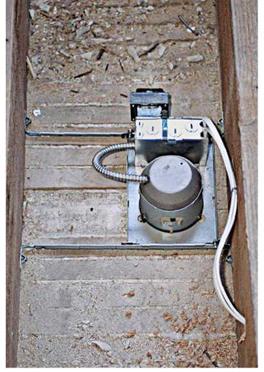
Подпись: PRO"ГIP Test new outlets before patching walls or ceilings. If the outlet's not correctly wired, you can repair it without having to rip out a newly installed new patch to get access. 1111 Подпись: This is a low-voltage recessed lighting fixture, as seen from above. Adjustable hanger bars mount the fixture to the ceiling joists. Because this first-floor ceiling will not be insulated, it's acceptable to use a non-IC-rated fixture.image525Подпись: Fishing Cable to a Ceiling Fixture Подпись: Ceiling fixture Подпись:If the cavity above isn’t accessible, cut out a larger area of ceiling to expose the ceiling joists, so you can fish cable and mount the box. If the ceiling fixture’s location isn’t critical, use nail-in boxes with brackets, which have the smallest footprint to patch. If you use a hanger bar, cut a channel in the ceiling from joist center to joist center so you’ll have something to attach the patch ends to. If the ceiling is plaster, drill 18 in. holes to find the width of one piece of lath, usually 1 in. wide. You’ll reduce patching if you can remove just one lath strip. See Chapter 15 for more about patching plaster and drywall.
INSTALLING CUT-IN BOXES

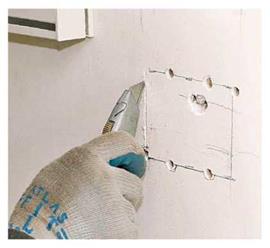
Cut-in boxes have special mounting devices that enable you to mount them directly to finish sur­faces. But first you’ve got to cut a hole for them. Hold the new box at the same height as other outlet boxes in the room, lightly pencil trace around the box, and then drill a small exploratory hole to locate studs or wood lath behind. Insert an offset screwdriver or a bent coat hanger in the hole and twirl it. If the tool hits a stud, move the box till it’s clear. If you hit wood lath, keep drilling small holes within the opening till you find the edges of the lath. If you position the box

correctly, you should need to remove only one section of lath. Cut-in box ears (also called plaster ears) mount to the lath top and bottom, so you may need to adjust the box height to make that happen.

Once you settle on a final location, level the box, trace its outline firmly onto the wall, and use a utility knife to score along the outline to mini­mize plaster fractures. (If the surface is drywall, don’t bother scoring; just go ahead and cut out the opening.) Plaster is delicate stuff, but a cord­less jigsaw can cut plaster without pulverizing it if you hold the saw shoe slightly above the sur­face. (Drill several J4-in. holes around the outline so you can insert the sawblade.) Finally, when cutting through the lath strip you’ll remove, alter­nate partial cuts from one side of the opening to the other; if you cut completely through one side of the lath first, that end will vibrate wildly and crack the plaster. After you’ve cut out around the box ears, predrill the lath so the mounting screws don’t split it. (If there’s metal lath, use a fine­toothed metal-cutting blade, and proceed slowly.)

Before inserting cut-in boxes, remove knock­outs, insert cable clamps, strip sheathing off the ends of incoming cable, feed cable into the cable clamps, and tighten the clamps down. Box mounts vary. Boxes with plaster ears that screw
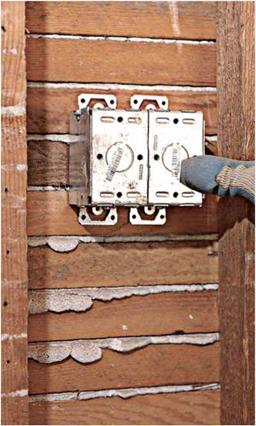
to wood lath are the most common. Spring-clip types have metal wings that expand once inserted in an opening. Grip-Tite boxes have side-mounted ears that stick out as you turn screws. Mounting tabs (also called elephant ears) slip into the space between the box and the edge of the hole; pull them tight against the wall, and bend the tabs into the box, using pliers. Flatten tabs so they cannot touch any terminal screw of the outlet. For good measure, wrap electrical tape around the devices, as shown in the photo on p. 243.

FISHING CABLE

© Once you’ve cut an opening for a cut-in box— but before inserting the box—fish the cable that will run from the existing outlet to the new one.

Подпись: TIPПодпись: Don't use cut-in boxes to house receptacles in high-use areas like bathrooms and kitchens. Plugs repeatedly inserted and removed will cause cut-in boxes—and possibly, electrical connections—to work loose. In such locations, you'll need to expose the framing and mount new-work boxes to it. 1111 image522,image523
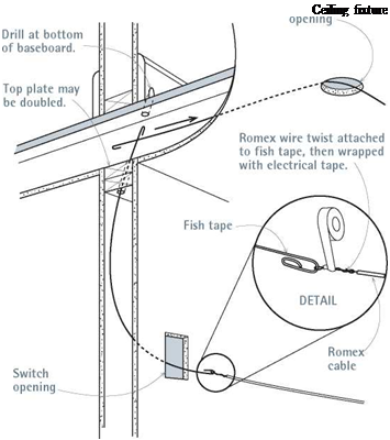
Fishing wires is easiest with a helper. As one person feeds metal fish tape down into an outlet cutout, the second person, with another fish tape, tries to catch the first. (Fish tape ends are often bent over to create a hook.) That accomplished, the first tape is pulled through, to have electrical cable attached to it. Bend and then twist the cable wires tightly over the fish tape, as shown in the drawing on p. 261, and wrap them well with electrical tape. Taper the electrical tape to a point

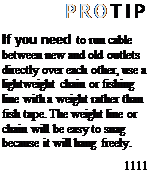
Подпись: PROTIP If you need to run cable between new and old outlets directly over each other, use a lightweight chain or fishing line with a weight rather than fish tape. The weight line or chain will be easy to snag because it will hang freely. 1111 Подпись: Retrofitting a I "Remodel" Lighting Fixture Подпись: Fixture can Подпись: This recessed lighting fixture is a special “remodel" unit, which is light enough to mount to finish surfaces. Attach the fixture leads to the incoming cable wires in the junction box, and then insert the fixture into the opening.so it will feed more easily into holes. If one per­son feeds the cable into the opening as the other pulls, the cable should move smoothly.
О To pull cable into an existing box, turn the power off, and then unscrew and gently pull the device out from the box and disconnect the wires attached to it. If the box is plastic, use a screw­driver to create a cable slot. If the box is metal, use a screwdriver to remove a knockout and to loosen the cable clamp nearest the knockout. If a metal box has no internal cable clamp, drill and tap a threaded hole so you can add a clamp. Feed the fish tape through the knockout opening; then pull in new cable and clamp it down.

Run a generous length of cable between the two boxes, so at least 1 ft. of cable protrudes from each box. Strip cable sheathing, tighten cable clamps, group like wires, and attach devices as described earlier. Chapter 15 covers patching finish surfaces.

MOUNTING CEILING FIXTURES

How you mount ceiling fixtures depends mostly on the weight of the fixture and whether framing is accessible. New “remodel” fixtures such as that shown below are light enough to mount to dry – wall or plaster ceilings, but heavier fixtures must be mounted to an adjustable hanger bar attached to ceiling joists or to a metal outlet box secured to the framing. Note: To prevent heat buildup and fire, fixtures in insulated ceilings must be rated

IC (insulation compatible) or insulation must be blocked back at least 3 in. from non-IC-rated fixtures.

Recessed lighting fixtures can usually be installed from below. О is cable in the ceiling cavity—either from an old fixture that was removed or from new cable recently fished to that location—and that the cable is not energized.

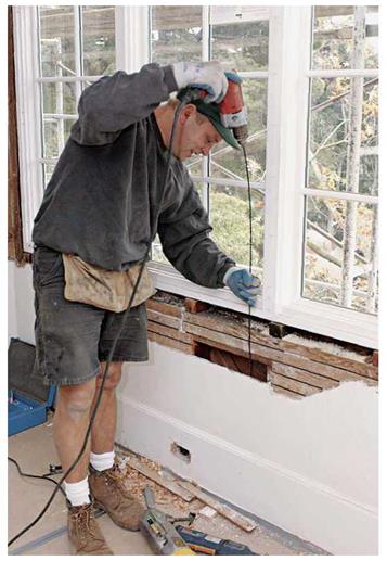
If there was no old fixture in the location, use a cordless drill to drill a 18-in. exploratory hole. Then insert a bent coat hanger into the hole and twirl it to locate nearby joists. Trace the template for the fixture can (housing) onto the ceiling.

Adding Outlets to Existing Circuits

Adding an outlet may be relatively simple if you can access an existing outlet and run a length of cable to a new outlet in the same wall cavity. But even the simplest setup needs a bit of planning— and some exploration—beforehand.

IMPORTANT PREP STEPS

Here are some tasks to do before working in an existing circuit:

► Check local electrical codes, which may not allow extensions of ungrounded circuits. The NEC forbids tying into specialized kitchen, bathroom, or dedicated-appliance circuits.

The circuit you tie into must be a 15-amp or

20- amp general-use or lighting circuit.

► Using a circuit map like that shown on

p. 234 will help you calculate how much power the new circuit will draw. Add up the wattage of all lights and appliances you’ll use on the circuit—plus that of tools if it’s an outdoor outlet. If the total exceeds 1,440 watts for a 15-amp circuit, you’re better off installing a new circuit to serve the new outlets.

►0 Turn off the power and test all affected outlets—including switches—with a voltage tester to make sure the power is off (see "Using a Voltage Tester," on p. 235). If you flip a circuit breaker to cut power, tape the service-panel door shut and put up a sign warning others of work in progress.

► Using cordless tools with plastic housings also reduces the risk of shock. Wear protection if you use power tools.

► After testing verifies that the power is off, unscrew the receptacle and gently pull it from the wall so you can check the capacity of the box. If the box is already crowded—which you can tell just by looking—there may not be room for an additional cable. Consult the table "Box Fill Worksheet, " on p. 240, to be sure. It is possible to replace the existing box with a larger one, but that will complicate

the task.

POSITIONING NEW OUTLETS

After deciding where you’d like a new outlet, find an existing outlet close to it. Think spatially: The closest outlet may be on the other side of a wall or on a floor above or below. Any existing outlet
is a likely candidate as long as it is live all the time—and not controlled by a switch upstream.

That decided, next figure out how to run cable with a minimum of drilling, wire fishing, and destroying of finished surfaces. If the nearest existing outlet is on another floor, look for a wall that contains plumbing that runs from floor to floor (a “pipe chase”). Also, there’s often room to run cable in the voids around stairwells. Closets that line up vertically are also good places to hide cable, patched walls, and discrete holes.

Drilling through wall plates. If there’s an un­finished attic or basement, you may be able to locate a wall in which to run cable by noting where existing cables or pipes emerge, where sole plates have been nailed through a subfloor, or where attic joists rest on wall top plates. When dropping cable down from above, first drill two pilot holes in the top plate—one hole to shine a flashlight into, the other to look into—to see if

A 4-ft. flexible drill bit is one way to drill through wall plates to reach a power source below. Because its diameter is less than ’A in., the bit shaft tends to wander. Wear heavy gloves so you can guide the bit without hurting your hands. Drill slowly.

INSTALLING A CUT-IN BOX

Ideally, a cut-in box should be positioned so that you need to remove only one complete lath strip and so the box’s plaster ears can be screwed into lath strips that are continuous.


image521

1. After test-drilling to locate the edges of a lath strip, level and outline the box, and drill several holes for a jigsaw blade—the more holes, the better. Before sawing, score the outline to minimize plaster cracking.


image520

there are obstructions such as fire-stops in the stud bay. Professionals sometimes have a helper stand near an outlet they’re drilling toward, who lightly places his or her hand on the wall to tell if a bit is on target. (You can feel the vibration of the bit.) Obviously, this takes skill and slow, care­ful drilling to avoid goring the helper.

Another approach: Drill exploratory holes by facing the outlet and angle drilling a Мб-in. hole at the base (or top) of the wall. Once the Мб-in. bit hits open space, insert a length of coat hanger or wire to find the hole more easily, above or below. If exploratory holes are in the right place, use a 18-in. bit to enlarge the holes.

If there’s no accessible attic or basement, you may need to cut small holes at the top or base of finish walls so you can angle-drill through wall plates and fish cable. For this you may need to pull back carpeting or remove baseboard mold­ing temporarily.

Behind baseboards. Running cable behind baseboards may be the best way to minimize damage to plaster or drywall. О First, turn off power to the area, and check to be sure it’s off; then remove the baseboard trim. If you use a nail set to drive finish nails through the trim, you’ll be less likely to break it. Once the baseboards are off,
use a cordless circular saw to cut along the bottom of the finish wall, 3 in. to 4 in. up from the floor. Set the sawblade to the depth of the finish surface so you don’t cut into studs or through electrical cables hidden in the walls. (Wear safety glasses.) Use a flat bar to pry up the finish wall slot.

Next, create a pathway for running the cable by drilling holes through studs; by notching stud edges !2 in.; or by cutting a slot in the back of the baseboard, if it’s thick enough. Whatever approach you choose, install Иб-in. steel nail – protection plates afterward to keep screws or nails from puncturing the cable.

Making Sense of Flexible Metal Cable

There are two main types of flexible metal cable, armor clad and metal clad. Outside, they look about the same. (For a comparison, see the photo on p. 238.) The main difference is that MC cable contains an insulated ground wire so it can ground equipment and tools with a three-prong plug. MC cable assemblies should be used in exposed dry locations, such as garages and basements. PVC-jacketed MC cable can be used outdoors, but it is so expensive that it is rarely used in residences. Note:

Exposed doesn’t mean "exposed to the ele­ments." Here it means visible and accessible— not hidden behind finish walls.

AC cable, on the other hand, contains no ground wire; rather, its metal sheathing serves as an equipment ground. AC should be used only in dry, indoor locations. The thin, uninsu­lated copper aluminum wire inside AC is not a conductor; it’s a bonding wire, which enhances the grounding ability of the armor itself. That is, AC’s grounding path is its metal sheathing.

The NEC allows both MC and AC to be used in branch circuits, but for the reasons just cited, many local codes allow only MC in new con­struction. In the text, MC is the default term for any flexible metal cable.

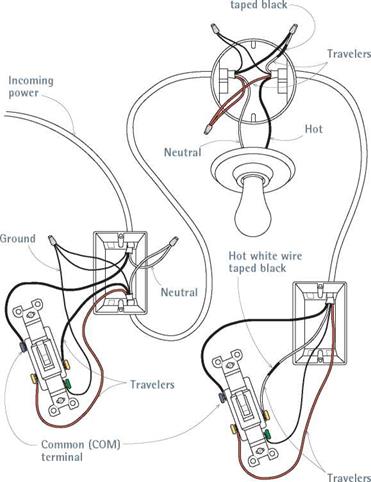
Подпись: I Three-Way-Switch Wiring Подпись: Hot white wireimage515

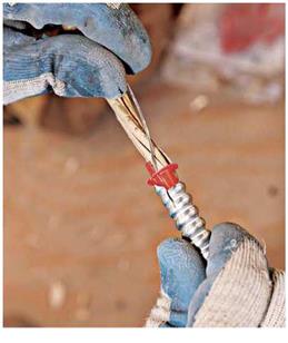
Подпись: Insert anti-short bushings between wires and sheathing, to protect the wire insulation from the sharp edge of the metal sheathing.
image516

sometimes used as a whip, a short section of exposed cable that connects permanent appli­ances or lighting fixtures to a circuit.

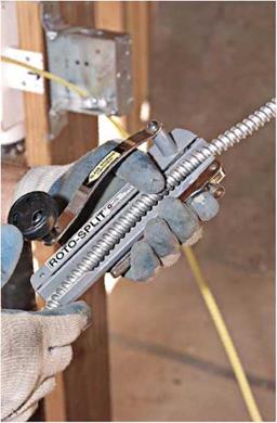
There are at least two ways to cut MC cable. The first method requires looping and squeezing the cable till its coils pucker and then snipping through the pucker with metal shears or diagonal-nose cutters, being careful not to nick the insulated wires inside. The second method is often required by local codes and is far easier: The rotary cable cutter shown in the photo below uses a hand-cranked cutting wheel to cut through metal sheathing. Once the tool cuts through a coil, slide the severed sheathing off the insulated wires inside.

Rough cut lengths of cable about 2 ft. longer than the distance from box to box, to allow for generous loops at turns. After you have removed the metal sheathing, rip free the Mylar® wrap between its outer sheathing and the insulated conductors inside (AC cable has kraft paper sur­rounding its wires). To prevent the severed sheathing from slicing the insulation of individ­ual wires, insert a plastic or fiber anti-short bush­ing between the wires and the sheathing, as shown below right. Note: Anti-short bushings are not required when using UL-listed MC cable clamps, but they are required by code (and man­ufacturers) for AC cable.

image517

Roto-Split cutters cut through armored cable sheathing quickly and cleanly, without damaging the insulation of individual wires inside.

Here’s a representative three-way setup (there are many possible configurations). Whenever you use a white wire as a switch leg, tape it black to indicate that it’s hot. Here, all boxes are nonmetallic.

Подпись: PROTIP Use polyethylene fish tape to pull wires in metal conduits. Flat steel fish tapes can cut and create burrs in metal conduit, and they tend to become jammed up at conduit bends. llll Подпись:

Once you’ve inserted the bushing, attach an appropriate cable connector to the end of the sheathing; most connectors employ a locknut that holds the threaded connector to a metal box. (Pull the BX bonding wire outside the sheathing and wrap it once around the connector screw; the bonding wire doesn’t go into the box.) After the cable connector is secured to the metal box, snip incoming wires so they are roughly 8 in. long. Splice and attach them to devices, as you would wires in nonmetallic cable

Because metal cable is flexible, support it every 6 ft. along its run and within 1 ft. of box connections. Staples should be snug but should not crimp the sheathing. The most common method of attaching cable is stapling it to the undersides or sides of joists where the cable runs parallel. When the cable runs perpendicular to framing, drill 58-in. holes through the center of the studs or joists and feed the cable through.

Note: Flexible metal cable can be punctured by drywall screws, so keep the cable back at least 114 in. from stud or joist edges. Otherwise, use steel nail-protection plates to safeguard the cable.

CONDUIT

There are several types of conduit, including thin-walled electrical metal tubing (EMT), rigid metal conduit (RMC), flexible metal conduit (FMC), and rigid nonmetallic conduit (RNC), which is made of PVC plastic. With metal con­duit, the conduit pipe is the equipment ground. Fittings are specific to each type of conduit and may vary further if the conduit is to be used underground or in high-moisture areas. Most types approved for exterior use will have weather­proof compression fittings. All conduit boxes must also be gasketed to keep moisture out.

Because conduit comes without wires inside, you must pull wire through it. Although wire can usually be pushed easily through straight lengths of conduit 10 ft. or less, use fish tape to pull wires around bends or through longer lengths.

First, use a conduit whose diameter is large enough for the number of wires you need to pull: 52-in. interior diameter (I. D.) conduit will suffice for most runs of 12AWG wire; use 54-in. I. D. con­duit for the heavier wires, such as 8AWG or 6AWG wire, needed for stoves and such. Check your local code requirements. Using pulling com­pound (also called pulling lube) will make the task easier, as will having one person to feed wire and one to pull. THHN wire, whose coating is especially slick, is often specified when pulling is necessary. To keep wires from pulling off the fish tape, bend them tightly over the end of the tape, and wrap well with electrical tape.

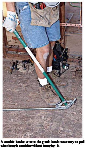
Pull wire only after you’ve attached conduit to boxes. If conduit bends more than the equivalent of four 90° bends between two boxes, you’ll need a pull box in the middle of the run, through which wires can be pulled. Too many bends cre­ates too much friction to overcome and can stress the wire too much. Such boxes give you access to the middle of the run. To shape bends, use a conduit bender, which slides over the con­duit. Bend the conduit, pushing down heavily on the shoe and bend till you achieve the desired curve: For 52-in. EMT conduit, a radius of about 552 in. is usual for a 90° bend. The bender will have arrows that indicate turning radiuses. Use a hacksaw to cut metal conduit; then use a debur – ring tool to smooth the cut ends and remove any metal spurs that could nick the conductor insulation.

Support EMT conduit at least every 10 ft. and within 3 ft. of termination. Connections within boxes are essentially the same as those for Romex cable, the principal difference being that

Подпись: TIPПодпись: Don't add outlets to circuits that have ungrounded cable; wires with frayed, discolored, or melted insulation; blackened metal boxes or other signs of arcing; or aluminum wire (a soft, dull silver) rather than copper. 1111 image519

the conduit itself, because it is metal, provides the grounding. To ground individual outlets, run a grounding pigtail from the grounding screw on the device to the metal box.