Category RENOVATION 3

ALERT

Dielectric unions have insu­lators inside that will not con­duct electricity. If your electrical system is grounded to the water main and you install a dielectric union to join copper pipe to a galvanized steel service pipe, for example, install a bonding jumper to ensure continuous grounding.

llllll

Water-supply pipe supports. Clockwise from upper/eftvtwo Acousto-Plumb® clamps (which reduce pipe noise by cushioning vibrations), a copper pipe strap, a 3A-in. by 6-in. plastic-coated wire hook, two plastic suspension clamps, and a felt-lined J-clamp.

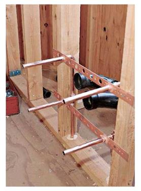
Подпись: After running DWV branch drains to fixtures, install supply-pipe assemblies and solder stub-outs to perforated strap.image599

less. Support horizontal runs of CPVC supply pipe every 3 ft.; vertical runs should be suported every 10 ft., with clamps or plumber’s strap attached to blocking. Support PEX tubing every 32 in. on horizontal runs and every 10 ft. on verti­cal runs (with mid-story guides).

Keep hot and cold pipes at least 6 in. apart. They should never touch. To conserve energy, reduce utility bills, and get hot water sooner at fixtures, install closed-cell foam insulation sleeves on hot-water pipes, as shown in the photo on p. 224. As noted earlier, water-supply stub – outs should protrude at least 6 in. into living space. To hold stub-outs in place, solder them to perforated copper straps nailed or screwed to studs.

Code requires shutoff valves for every fixture riser. Supply pipes to outdoor spigots or unheated rooms should have shutoff valves and unions within the main basement so pipes can be drained. Install water-hammer arrestors on branch lines to appliances such as washers or dishwashers, whose solenoid valves stop water flow so abruptly that pipes vibrate and bang against the framing.

To test the supply system before installing dry- wall, solder caps onto fixture stub-outs and turn on the water. (If you’re installing CPVC supply,

cement caps onto stub-outs.) If there are no leaks, install steel nail-protection plates over any pipes that lie within 114 in. of a stud edge, or use steel stud shoes over notched studs. Then install finish surfaces.
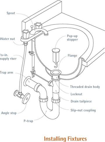
image600Подпись: I Lavatory AssemblyПодпись:Подпись: When connecting supply lines to fixtures, code requires hot on the left, cold on the right. When your eyes are shut tight against soapsuds and you're fumbling for a faucet, it's reassuring to know which spigot is which.Подпись: llll Lavatory or sink supply pipes may have unions that can be disconnected using two pipe wrenches. Otherwise, water-supply nuts (water nuts) will connect the tops of supply risers to threaded faucet stems on the underside of the basin. To loosen water nuts, use a basin wrench, which has a shaft 10 in. to 17 in. long and spring-loaded jaws set at a right angle to the shaft. If the lav isBefore you can install a new fixture, there’s often an old one to remove. If it’s necessary to shut off water to several fixtures during installation, capping disconnected pipes will allow you to turn the water back on.

Before disconnecting supply pipes, shut off the valves that control them. As mentioned, code requires a shutoff valve on each fixture riser, but older systems may have only a main valve that shuts off water to the whole house. After shutting off the controlling valve, open the faucets to drain the water.

old and you intend to reinstall it, save the water nuts because the threaded faucet stems may be nonstandard.

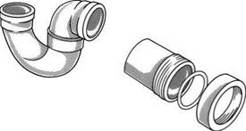
To disconnect a fixture’s drainpipe, use two pipe wrenches to loosen the slip-nut coupling of the P-trap. If older galvanized couplings have seized up, heat them with a MAPP gas torch and tap them lightly with a hammer to free the joint. Then try again with wrenches. Be sure to wear a respirator mask to avoid inhaling smoke from gaskets and such.

Once you’ve disconnected the drain and sup­ply pipes, lift the lav/sink off its wall hanger, pedestal, or cabinet base and set it aside. An old cast-iron lav can be quite heavy, so lift it with the aid of helper. Place a plastic bag over the drain pipe stub and secure it with a rubber band to keep sewer gases at bay. Disconnect fittings care­fully if you want to reuse them.

To remove a toilet, shut off the water by shut­ting the chrome fixture stop near the base of the unit. Flush the toilet and remove the remaining water with a cup or an inexpensive plastic hand pump. Disconnect the tank from the toilet bowl by loosening the bolts that hold the sections together. If the tank is wall hung, use a wide – jawed spud wrench to loosen the slip nut between the tank and the bowl. The toilet bowl is fastened to the floor by two bolts that rise from the floor flange; unscrew the nuts capping the bolts on both sides of the bowl. Rock the toilet bowl slightly to break the wax seal on the bottom.

Then lift up the bowl and immediately block the drainpipe by stuffing it with a plastic bag con­taining wadded-up newspapers.

Tub drain assemblies may be hidden in an end wall or they may exit into a hole cut into the sub­floor under the drain. The drain and overflow assembly is usually held together with slip cou­plings, so use a pipe wrench to loosen them. If the drain is solid piece, cut through it. Supply pipes may be joined with unions or they may be soldered; it’s easiest just to cut through supply risers. With those pipes disconnected, you can move the tub.

If it’s a standard tub (rather than a free­standing tub), you may need to cut into the finish surfaces at least 1 in. above the tub to expose the tub lip, which is often nailed to studs. If you’re discarding the tub and don’t care about chipping its enamel, use a cat’s paw to pull the nails. If the tub is too heavy or tightly fit to slide out of its alcove, you may need to cut the studs of the end wall so you can slide the tub out.
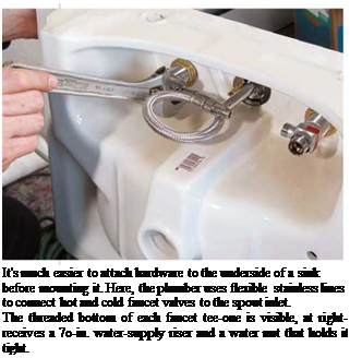
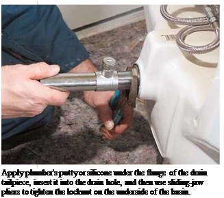
Подпись: It's much easier to attach hardware to the underside of a sink before mounting it. Here, the plumber uses flexible stainless lines to connect hot and cold faucet valves to the spout inlet. The threaded bottom of each faucet tee-one is visible, at right-receives a 7o-in. water-supply riser and a water nut that holds it tight. Подпись: Apply plumber's putty or silicone under the flange of the drain tailpiece, insert it into the drain hole, and then use sliding-jaw pliers to tighten the locknut on the underside of the basin. Подпись:Подпись:Подпись:

INSTALLING LAVATORIES AND SINKS

Lavatory basins and sinks are supported by pedestals, cabinet counters, legs, wall-mounted brackets, or a combination of these. Cabinet-mounted lavs and sinks are particularly popular because they provide storage space.

Preassemble the hardware. Before mounting a sink or lav, attach its hardware, including faucets, spout, and the drain tailpiece. Such connections are easier to make when the fixture is inverted. Insert the threaded faucet stems through pre­drilled holes in the sink or lav body, and tighten the washered nuts on the underside. Many manu­facturers supply a rubber gasket; but when that’s lacking, spread a generous layer of plumber’s
putty between the metal and the porcelain. Don’t overtighten. Once the faucets are secure, you can connect the risers loosely to the threaded faucet stems, allowing you to reposition them if needed when attaching their lower ends to the angle stops.

Set the unit. Sink (or lav) installations vary, depending on whether the unit is surface mounted, under mounted, flush mounted, wall mounted, or set atop a pedestal. Once you’ve attached the hardware, apply a bead of silicone caulk to the sink lip, turn the unit over, and press it flat to the surface (or underside) of the counter. Some sinks need nothing more to secure them, although many have mounting clips similar to

TESTING THE DWV SYSTEM

Once you’ve roughed out the DWV system, but before hooking up fixtures, test for leaks. Filling DWV pipes with water is a common test, which requires that you seal all fixture stub-outs and use a garden hose to fill the largest stack. (All DWV pipes are interconnected, so you need fill only one stack to fill all.) Should you see leaks, drain the system, fix the leaks, and refill. Once

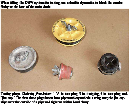
Подпись: SAFETY ALERT Electrical service is often grounded to metal water-supply pipes. Thus they may be energized. To avoid shocks when cutting into such pipes, use a cordless reciprocating saw with a metal-cutting blade, rather than a corded saw. The cordless saw's plastic casing will also insulate against shocks if pipes are energized, as will rubber gloves. Before cutting, shut off the water and open faucets to drain the pipes. llllll Подпись: When filling the DWV system for testing, use a double dynamiter to block the combo fitting at the base of the main drain. Testing plugs. Clockwise, from bottom: 1 ’A-in. test plug, 3-in. test plug, 4-in. test plug, and "jim cap." The first three plugs insert into pipes and expand via a wing nut; the jim cap slips over the outside of a pipe and tightens with a band clamp. you see no leaks, allow the water to stand at least overnight or until the inspector signs off on your system.
There are several types of pipe seals. The most common and least expensive is a glue-on cap that fits inside a DWV pipe stub. Allow pipe cement to dry a day before filling pipes with water. When the test is completed, drain the system by open­ing a cleanout at the lowest point, and cut off the small sections of drainpipe in which caps are

image597

glued. Where a stack is several stories high, this is the only type of cap guaranteed not to be dislodged by a weighty column of water.

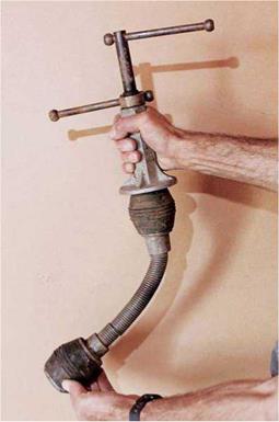
Reusable rubber caps or plugs eliminate the need for gluing. A jim cap fits over the end of a pipe and tightens with a ring clamp. Test plugs fit into pipe ends and are expanded by a wing-nut assembly. A third type, known as a double­dynamiter out West, can be rented. It is a spring – loaded device that fits into the combo at the foot of the building drain. As shown in the top photo at left, this tool has two rubber balls that can be expanded or contracted by turn screws on the shaft. Insert the balls so that the forward one lodges in drainpipe, and then expand that ball; the second ball should block the open leg of the combo. To release the water, contract the balls of the double-dynamiter in the order in which you expanded them. Loosened, the forward ball will allow the test water to run down the drain; releasing the second ball allows you to remove the tool. Label the respective turn screws so you don’t confuse them: If you release the second ball first, you may get a faceful of waste water.

If there are finish ceilings in place below new pipes and you don’t want to risk wetting them with a failed connection, use an air-pressure test in which all openings (including stacks) are sealed. Typically, an inflatable bladder attached to a gauge is inserted into a cleanout at the base of the soil stack, and air is pumped into the DWV system. If the gauge shows no pressure loss over a given period, the inspector signs off.

Roughing-In Supply Pipes

Water-supply pipes are easier to run than DWVs because they’re smaller and don’t need to slope. Metal supply pipes should be bonded to the house’s electrical grounding system (see p. 231).

Run supply pipes to fixtures once hot and cold trunk lines are connected. Run 24-in. trunk lines, using 12-in. pipe for branch lines serving two fix­tures or fewer. Individual supply risers for toilets and lavatories are often 28 in. You save some money by using smaller-diameter pipes, but the main reason to reduce pipe diameter is to ensure adequate water pressure when several fixtures are used simultaneously. Reducing tees, such as the 22 by 12 shown in the bottom photo on p. 270, provide a 12-in. branch takeoff from a 22-in. trunk line.

Support horizontal runs of copper supply pipe at least every 6 ft., but if pipes run perpendicular to joists, plumbers usually secure the pipe every second or third joist. Support vertical runs of copper at every floor or every 10 ft., whichever is

Drilling and Notching Studs and Joists

Подпись: Notching and Drilling LimitsПодпись: JOISTS

It’s often necessary to notch or drill framing to run supply and waste pipes.

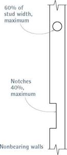
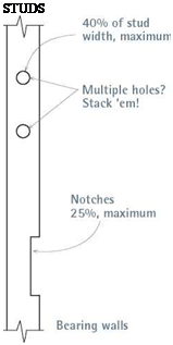
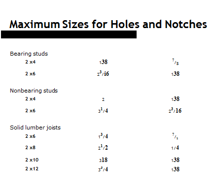
If you comply with code guidelines, given in "Maximum Sizes for Holes and Notches," on p. 287, you’ll avoid weakening the struc­ture. Although that table is based on the following rules of thumb, remember that local building codes have the final say.

Joists

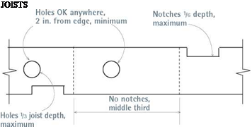
You may drill holes along the entire span of a joist, provided the holes are at least 2 in. from the joist’s edge and don’t exceed one – third of the joist’s depth. Notches are not
allowed in the middle third of a joist span. Otherwise, notches are allowed if they don’t exceed one-sixth of the joist’s depth.

Studs

Drilled holes must be at least 78 in. from the stud’s edge. Ideally, holes should be centered in the stud. If it’s necessary to drill two holes in close proximity, align the holes vertically, rather than drilling them side by side. Individual hole diameters must not exceed 40 percent of the width of a bearing-wall stud, if those studs are doubled and holes don’t pass through more than two adjacent
doubled studs; hole diameters must not exceed 60 percent of the width of non­bearing-wall studs. Notch width may not exceed 25 percent of the width of a bearing – wall stud or 40 percent of the width of a nonbearing-wall stud.

Edge protection

Any pipe or electrical cable less than 11/ in. from a stud edge must be protected by steel nail plates or shoes at least Ум in. thick, to prevent puncture by drywall nails or screws.

Pipe Slope

DWV pipes slope, so before drilling or notch­ing framing, snap sloping chalklines across the stud edges; then angle your drill bits slightly to match that slope. Drill holes 74 in. larger than the outside dimension of the pipe, so the pipe feeds through easily. Nonetheless, if DWV pipe runs are lengthy, you may need to cut pipe into 30-in. sections (slightly shorter than the distance between two 16-in. on-center studs) and join pipe sections with couplings. That is, it may be impossible to feed a single uncut DWV pipe through holes cut in a stud wall.

image593Подпись: STUDS When hole diameters exceed maximur allowed by code, reinforce framing wi1 a steel stud shoe.
_

tim: –

W

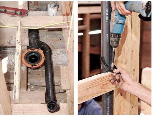
The toilet flange (orange ring) will sit atop the finish floor. So if the finish floor is not yet installed, place scrap under the flange, elevating it to the correct height. This assembly is essentially the same as that shown in “Constricted Spaces," on p. 282.


Support vent stacks in mid-story by using plumber’s strap to tie stacks to blocking between studs.


image595

Подпись: TIPПодпись: Use only noncorroding (brass or stainless-steel) screws and bolts to secure the closet flange or the toilet bowl; other materials will corrode. To help you align the bolt holes on the bowl with bolts in the closet flange, buy extra-long, 3-in. by 5/i6-in. closet bolts. They'll be long enough to line up easily, even when the wax ring is in the way, and you can trim excess length without difficulty. 1111
Once you’ve secured the closet bend, add pipe sections to the bottom of the bend, back to the takeoff fitting on the main drain that you installed earlier. Maintain a minimum of!4 in. per foot slope, and support drains at least every 4 ft. Dry-fit all pieces, and use a grease pencil to make alignment marks on pipes and fittings.

Other fixture drains. Next run the 1!4-in., 112-in., and 2-in. fixture drains up from the main drain takeoff. Drains must slope at least 14 in. per foot, and all pipe must be rigidly supported every 4 ft. and at each horizontal branch connection. Support pipes with rigid plastic pipe hangers or with plastic-pipe strap, securing pipes to wood blocks beneath them. Support stacks at the base, and in mid-story by strapping or clamping the pipe to a 2x block running between studs.

Run the tub branch drain to the subfloor opening where the tub trap arm will descend.

Pipe stub-outs for lavs and sinks should stick out into living spaces 6 in. or so; you can cut them off or attach trap adapters later. All branch drains end in a sanitary tee. The horizontal leg of the tee receives the trap arm from the fixture, and the upper leg of the tee is the beginning of the branch vent.

Vent runs. Next assemble vent runs, starting with the largest vent—often the 2-in. or 3-in. pipe rising from the combo fitting below the closet bend. Individual branch vents then run to that vent stack, usually joining it in an inverted tee fit­ting, typically 4 ft. to 5 ft. above the floor. Support all stacks in mid-story with clamps or straps. Horizontal runs of 112-in. branch vents must be at least 42 in. above the floor, or 6 in. above the flood rim of the highest fixture, and those runs typically slope upward at least 14 in. per foot. Continue to build up the vent stack, with as few jogs as possible, until it eventually passes through a flashing unit set in the roof. For code requirements at the roof, see "Vent Termination,” on p. 284.

Framing for Toilets and Tubs

You may need to cut through joists to accom­modate the standard 4 by 3 closet bend beneath a toilet or the drain assembly under a standard tub. In that event, reinforce both ends of sev­ered joists with doubled headers attached with double-joist hangers. This beefed-up framing provides a solid base for the toilet as well.

If joists are exposed, you can also add joists or blocking to optimize support.

Toilets

A minimum 6-in. by 6-in. opening provides enough room to install a no-hub closet bend made of cast iron (41/2 in. outer diameter) or plastic (З1/? in. outer diameter). The center of the toilet drain should be 12 in. from a finish wall or 1232 in. from rough framing. If joists are exposed, add blocking between the joists to stiffen the floor and better support the toilet bowl, even if you don’t need to cut joists to position the bend.

Bathtubs

A 12-in. by 12-in. opening in the subfloor will give you enough room to install the tub’s waste and overflow assembly. Ideally, there should be blocking or a header close to the tub’s drain, that you can pipe-strap it to. To support the fittings that attach to the shower arm and spout stub-outs, add cross-braces between the studs in the end wall. To support tub lips on three sides, attach ledgers to the studs, using galvanized screws or nails. Finally, if there’s access under the tub, add double joists beneath the tub foot.

a sleeve onto each end of the combo. Align the combo takeoff so it is the correct angle to receive the fixture drain you’re adding. Finally, tighten the stainless-steel clamps onto the couplings.

CONNECTING

BRANCH DRAINS AND VENTS

After modifying the framing, assemble branch drains and vents. Here we’ll assume that the new DWV fittings are plastic.

The toilet drain. After framing the tub drain opening, install the 4 by 3 closet bend, centered 12 in. from the finished wall behind the toilet. Install a piece of 2×4 blocking under the closet bend, and end-nailed through the joists on both ends. Use plastic plumber’s tape to secure the bend to the 2×4. What really anchors the closet bend, however, is the closet flange, which is cemented to the closet bend and screwed to the subfloor.

The flange screws to the subfloor yet will sit atop the finish floor when it’s installed. If the fin­ish floor is not in yet, place scrap under the flange so it will be at the correct height. If, on the other hand, the flange is below the finish floor, you can build up the flange by stacking plastic flange extenders till the assembly is level with the floor. Caulk each extender with silicone as you stack it and use long closet bolts to resecure the toilet bowl. (Check with local codes first, because not all allow extenders.)

BUILDING OUT FROM THE MAIN DRAIN

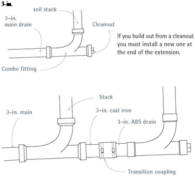
Extending the DWV system out from the end of a cast-iron main drain—where it joins the soil stack—can be the least disruptive way if there’s a cleanout at the end of the drain that you can remove. Before cutting the drain, support both sides of the section to be cut, using pipe clamps or strap hangers.

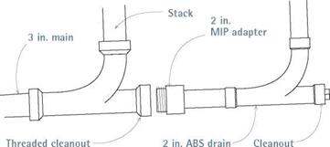
The exact configuration of the end run will depend on the size of the main drain, the fitting currently at the base of the stack, the fixtures you’re adding, and the size of the drain needed to serve them. If you are not adding a toilet, the drain extension can be 2-in. pipe, which can be attached with a reducing bushing such as the male-threaded adapters shown in "Extending with 2-in. ABS,” at left. If you’re adding a toilet, however, the extension must be 3-in. pipe, often inserted with a ribbed bushing to ensure a tight fit. If it’s not possible to insert the 3-in. pipe into an old cleanout leg, you may need to cut out the existing combo and install a no-hub combo to build out from.

Note: If you build out from an existing cleanout at the end of the main drain, you’ll need to add a new cleanout at the end of the extension.

TYING INTO THE MAIN DRAIN IN MID-RUN

Before tying into the main drain in mid-run, flush the drain and support both sides of the sec­tion you’ll cut into. Then install strap hangers to support both sides of the 3-in. or 4-in. drain. Tying into a cast-iron or plastic drain is essential­ly the same procedure as splicing into a stack, but it requires different fittings. So here’s how to tie into a cast-iron main drain. With one hand,

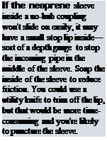
Подпись: If the neoprene sleeve inside a no-hub coupling won't slide on easily, it may have a small stop lip inside—sort of a depth gauge to stop the incoming pipe in the middle of the sleeve. Soap the inside of the sleeve to reduce friction. You could use a utility knife to trim off the lip, but that would be more time-consuming and you're likely to puncture the sleeve.Подпись: 1111Подпись: Maximum Sizes for Holes and Notches FRAMING ELEMENT HOLE DIAMETER (in. Bearing studs 2 x4 138 7/S 2 x6 23/i6 138 Nonbearing studs 2 x4 2 138 2 x6 31/4 23/16 Solid lumber joists 2 x6 13/4 7/s 2 x8 21/2 1/4 2 x10 318 138 2 x12 33/4 138

hold the no-hub combo fitting you’ll add next to the drain section and, with the other hand, mark cut-lines onto the drain using a grease pencil.

The cut marks should be 1 in. longer than the length of the fitting to accommodate the thick­ness of the stop lip inside each no-hub coupling’s neoprene sleeve. (If the main drain is cast iron, use a snap cutter to cut it; if it’s plastic, use a wheeled cutter.)

After cutting out the drain section, use no-hub couplings to attach the new no-hub combo fit­ting. Slide a neoprene sleeve onto each end of the cut drain, insert the no-hub combo, and then slide

Roughing-In DWV Pipes

In new construction, pros typically start the DWV system by connecting to the sewer lead pipe, sup­porting the main drain assembly every 4 ft. and at each point a fitting is added.

Renovation plumbing is a different matter altogether, unless an existing main is so corroded or undersize that you need to tear it out and replace it. Rather, renovation plumbing usually entails tying into an existing stack or drain in the most cost – and time-effective manner. There are three plausible scenarios: (1) cutting into a stack to add a branch drain, (2) building out from the end of the main drain where it meets the base of the soil stack, and (3) cutting into the main drain in mid-run and adding fittings for incoming branch drains.

This discussion assumes that the existing pipes are cast iron and that new DWV pipes or fittings are ABS or PVC plastic, unless otherwise noted. If you’re adding several fixtures, position
the new branch drain so that individual drains can attach to it economically—that is, using the least amount of pipe and fittings. As noted before, drainpipes must have a minimum down­ward slope of 14 in. per foot.

Run clear water through the drains before cutting into them. Flush the toilets several times and run water in the fixtures for several minutes. Then shut off the supply-pipe water and post signs around the house so people don’t use the fixtures while work is in progress.

SPLICING A

BRANCH DRAIN INTO A STACK

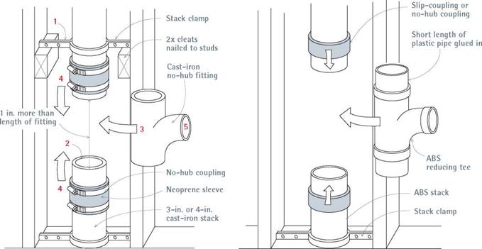
If you’re adding a toilet, have a plumber calculate the increased flow, size the pipes, recommend fit­tings, and—perhaps—do the work. Adding a lav, sink, or tub, on the other hand, is considerably easier and less risky—mostly a matter of splicing a 1 И-in. branch drain to a 2-in. or 3-in. stack. The keys to success are clamping the stack before cut­ting it, inserting a tee fitting into the stack, and joining the branch drain to that fitting.

Let’s look at splicing to a cast-iron stack first. Start by holding a no-hub fitting (say, a 2 by 1И sanitary tee) next to the stack and using a grease pencil to transfer the fitting’s length to the stack—plus И in. working room on each end.

(This will leave a И-in. gap at each end, which will be filled by a lip inside the neoprene sleeve.) Install a stack clamp above and below the pro-

THE Flow

To optimize flow and minimize clogged pipes, follow these guidelines:

► DRAINAGE FITTINGS. Use a long-sweep ell (90° elbow) or a combo when making a 90° bend on horizontal runs of waste and soil pipe, and where vertical pipes empty into horizontal ones. Use a standard ell when going from horizontal to vertical. Where trap arms join vent stacks, use sanitary tees. (Long-sweep fittings are not required on turns in vent pipe; regular tees and ells may be used there.)

. Cleanouts are required where a

building main joins a lead pipe from a city sewer line or septic tank, at the base of soil stacks, and at each horizontal change of direction of 45° or more. Also, install cleanouts whenever heavy flow increases the possibility of clogging, such as in back-to-back toilets. There must be enough room around the cleanout to operate a power auger or similar equipment.

Pipe-Support Spacing

PIPE MATERIAL

HORIZONTAL SUPPORTS

VERTICAL SUPPORTS

Water supply

Copper

6 ft.

10 ft.

CPVC

3 ft.

10 ft. and mid-story guide

PEX

32 in.

Base and mid-story guide

DWV

ABS or PVC

4 ft. and at

branch connections

10 ft. and mid-story guides if pipe < 2 in.

Cast iron

5 ft.

Base and each story; 15 ft.

Подпись:Подпись:image587Splicing a Branch Drain to a Stack

AN ABS-PLASTIC STACK


A CAST-IRON STACK


image588

Glue two short lengths of ABS pipe to a tee. Mark an equivalent length plus [2]/2 in. on both ends onto the ABS stack to indicate cutlines. (Each ABS slip-coupling has an inner lip that nearly fills the 1/2-in. space). Support and cut the stack. Finally, join the pipes by slipping the couplings in place.

Подпись: posed cuts. Then use a snap cutter to make the two cuts. Drill through studs as needed to run the branch drain. Next, slide no-hub couplings onto both cut pipe ends; in most cases, it's easiest to loosen the couplings, remove the neoprene sleeves, and roll a sleeve halfway onto each pipe end. (Lips inside the sleeves make them impossible to slide on.) I Extending a Cast-Iron Main Drain Подпись: 3-in. Подпись: EXTENDING WITH 3-IN. ABS If the present cleanout is a cast-iron inset caulked with oakum, remove the oakum and the inset and replace it with a short section of 3-in. cast-iron pipe. From there, use a transition (no-hub) coupling to continue with 3-in. ABS plastic. image590Подпись: EXTENDING WITH 2-IN. ABS If there's presently a threaded cleanout opening and you are adding a tub, lav, or sink—but not a toilet-use a plastic MIP (male X iron pipe) adapter.

Insert the no-hub fitting, unroll the sleeves onto fitting ends, slide the banded clamps over the sleeves, orient the fitting takeoff, and tighten the clamps with a no-hub torque wrench. Finally, use a transition coupling, which is a special no­hub coupling that accepts pipes of different outer diameters, to tie the new 112-in. plastic branch drain to the cast-iron no-hub coupling.

Tying into an ABS or PVC stack is essentially the same, except that you’ll use a wheeled cutter to cut the stack. And, instead of using a no-hub coupling, glue short (8-in.) lengths of pipe into the tee fitting and then use plastic slip couplings to join the 8-in. stubs to the old pipe. (The slip couplings also glue on, with an appropriate solvent-based cement.) Use a reducing tee, such as a 2 by 1h. Be sure to support the stack above and below before cutting into it.

VENTING TOILETS

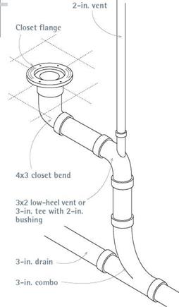
Because they have the biggest drain and vent pipes of any fixture, toilets can be the trickiest to route vents for. When space beneath a toilet is not a problem, use a setup such as the one shown below, in "Venting a Toilet,” in which a 2-in. vent pipe rises vertically from a 3 by 2 combo, while the 3-in. drain continues on to the house main. The 3-in.-diameter toilet drain, allows the vent to be as far as 6 ft. from the fixture, as indicated in the table on p. 281.

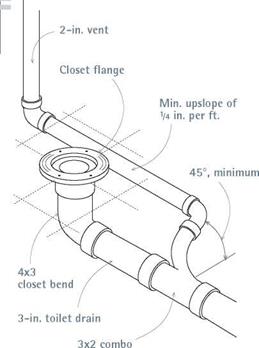
When space is tight, say, on a second-floor bathroom with a finish ceilings below, the drain and vent pipes must descend less abruptly (see "Constricted Spaces,” below. Here, the critical detail is the angle at which the vent leaves the 3 by 2 combo: That vent takeoff must be 45° above a horizontal cross section of the toilet drain. If it is less than that, the outlet might clog with waste and no longer function as a vent. As important, the "horizontal” section of the vent that runs
between the takeoff and the stack must maintain a minimum upward pitch of 1/4 in. per foot.

When you’ve got two toilets back to back, you can save some space by picking up both with a single figure-5 fitting (double combo), like the small one in the bottom photo on p. 277. From the top of the fitting, send up a 2-in. or 3-in. vent; from the two side sockets use two 3-in. soil pipes serving the toilets; and use a long-sweep ell (or a combo) on the bottom, to send wastes on to the main drain. This fitting is about the only way to situate back-to-back water closets and is quite handy when adding a half bath that shares a wall with an existing bathroom.

OTHER VENTING OPTIONS

Common vents are appropriate where fixtures are side by side or back to back. This type of vent usually requires a figure-5 fitting.

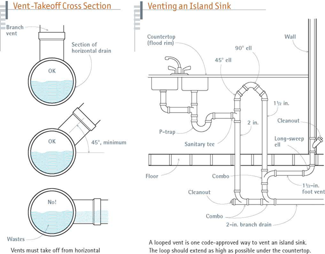
Loop vents are commonly installed beneath an island counter in the middle of a room. The sink

drain is concealed easily enough in the floor plat­form, but the branch vent, lacking a nearby wall through which it can exit, requires some ingenu­ity. This problem is solved by the loop shown in "Venting an Island Sink,” below.

In addition to the fittings shown in the draw­ing, note these factors as well: the loop must rise as high under the counter as possible and at least 6 in. above the juncture of the trap arm and the sanitary tee, to preclude any siphoning of waste­water from the sink. The vent portions may be 1 ’/2-in. pipe, but the drain sections must be 2 in. in diameter, and drain sections must slope down­ward at least ‘/ in. per foot.

Mechanical vents, also known as air-admittance valves, or pop vents, allow you to use a fixture before the vent runs are complete (say, before you run a vent stack up through the roof). Here’s how they work: As water drains from a sink, it creates a partial vacuum within the pipes, depressing a spring inside the vent and sucking
air in. When the water is almost gone and the vacuum is equalized, the spring extends and pushes its diaphragm up, sealing off outside air once again.

Mechanical vents are temporary vents only.

The UPC allows them only if local jurisdictions permit them—and few do. Because valve mecha­nisms can wear out and allow septic gases into living spaces, mechanical vents must never be used as permanent vents or in enclosed spaces where they cannot draw air easily.

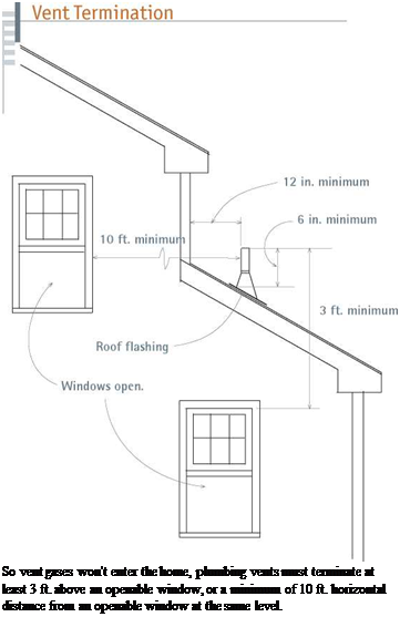
VENT TERMINATION

image585

To reduce chances that vent gases will enter the home, stack tops must be at least 6 in. above the upslope side of the roof and at least 3 ft. above any part of a skylight or window that can be opened. A vent stack must at least 12 in. horizontal distance from a parapet wall, dormer sidewalls, and the like. Finally, stacks must be correctly flashed to prevent roof leaks.

Подпись: When ordering supplies, order 20 percent more pipe than you think you'll need and at least a half-dozen extra of the more common fittings such as tees, combos, ells, and couplings. You'll also need straps and clamps to support pipe runs and consumables, such as solder or plastic-pipe cement and plumber's sand cloth. Most supply stores accept returns, but check their policy before ordering. 1111 Подпись: So vent gases won't enter the home, plumbing vents must terminate at least 3 ft. above an openable window, or a minimum of 10 ft. horizontal distance from an openable window at the same level. Подпись: GOING WITH THE

Venting Options

Until you expose the framing and actually run the pipe, it’s difficult to know exactly how things will fit together—especially vents. Because cor­rect venting is crucial, the section discusses sev­eral venting options to consider. But first, here are a few terms to keep straight: A stack is a verti­cal pipe. If the stack carries wastes, it’s a soil stack. If the stack admits air and never carries water, it’s a vent stack.

Most of the venting options described next are examples of dry venting, in which a vent stack never serves as a drain for another fixture. But there are hybrids; for example, if a vent stack occasionally drains fixtures above it, it is a wet vent. Wet vents must never carry soil wastes, and many local codes prohibit all wet venting. But when it’s legal and the vent is one pipe-size larger than normal to ensure a good flow, wet venting can be safe and cost effective because it requires fewer fittings and less pipe.

image580

No-hub couplings (also known as banded cou­plings, band-seal couplings, and hubless con­nectors) consist of an inner neoprene sleeve, which fits over the pipe ends or fittings, and an outer corrugated metal shield, which is drawn tight by a stainless-steel band clamp. No-hub couplings are widely used to join cast-iron pipe and no-hub fittings in new construction, but they are also invaluable to renovators.

For example, if you want to add a plastic shower drain to a cast-iron stack, no-hub cou­plings can accept either a cast-iron or a plastic no-hub fitting and seal it tightly to the pipe ends once you’ve cut into the stack. (Support both sides of the section to be cut out so it can’t shift during cutting and weaken other joints.)

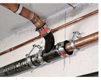
When joining DWV pipes of different materi­als, use specialized transition couplings whose neoprene sleeves are sized for incoming pipes with different outside diameters, such as the coupling used to join 2-in. copper and 2-in. cast iron, shown in the photo at left.

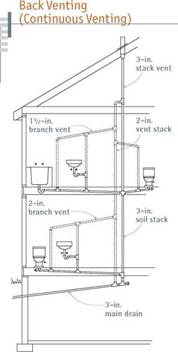
BACK VENTING

Back venting (also known as continuous venting), is the dry-venting method shown below, and it’s acceptable to even the strictest codes. All the fix­tures in the drawing have a branch vent. In a typical installation, the trap arm of, say, a lava­tory empties into the middle leg of a sanitary tee. The branch drain descends from the lower leg; the branch vent from the upper. When a branch vent takes off from a relatively horizontal section of drainpipe, the angle at which it departs is crucial. It may go straight up, or it may leave at a 45° angle, to work around an obstruction. But it must never exit from the side of a drainpipe:

If it did, it could become clogged with waste.

image581

In this illustration of back venting, all fixtures have a dry branch vent—that is, no vent ever carries water. The fixtures on the first floor require a 2-in. branch vent because the toilet’s 3-in. drain needs more incoming air to equalize its large waste flow.

Maximum Distance: Trap Arm to Vent*

TRAP ARM MAXIUM DISTANCE DIAMETER (in.) TO VENT

M

2 ft. 6 in.

M

3 ft. 6 in.

2

5 ft.

3

6 ft.

4

10 ft.

* Also maximum distance of stack-vented fixture trap arm to stack, based on calculations found in the UPC, T10-1.

Branch vents must rise to a height of at least 42 in. above the floor before beginning their hori­zontal run to the vent stack. This measurement adds a safety margin of 6 in. above the height of the highest fixture (such as a sink set at 36 in.), so there is no danger of waste flowing into the vent. Since branch vents run to a vent stack, they should maintain an upward pitch of at least!4 in. per foot; although the UPC allows a vent to be level if it is 6 in. above the flood rim of a fixture.

STACK VENTING

Clustering plumbing fixtures around a central stack is probably the oldest method of venting. In the early days of indoor plumbing, plumbers noticed that fixtures near the stack retained the water in their traps; whereas those (unvented) that were at a distance did not. You can vent three bathroom fixtures (lavatory, tub, and toilet) off a 3-in. stack vent, without additional branch vents—if you detail it correctly, as shown in "Stack Venting,” above right.

Note: When stack venting, never place a toilet above the other fixtures on the stack: Its greater discharge could break the water seals in the traps of small-dimension pipes. If you must add fix­tures below those already stack vented, add (or extend) vent stacks and branch vents. The maxi­mum allowable distance from stack-vented fix­tures to the soil stack depends on the size of the pipe serving a particular fixture; see "Maximum Distance: Trap Arm to Vent,” above.

Подпись: I Venting a Toiletimage583Подпись: When there's plenty of space under a toilet—say, an unfinished basement— the branch drain can descend steeply.

Подпись: I Constricted Spaces
image584
Подпись: When a branch drain must travel through a floor platform before reaching a stack, the drain must slope gradually. Here, the angle the vent takes off from the toilet drain is critical—it must not be less than 45°, as depicted in the cross-section drawing at right.

PEX: The Rising Star of Supply Pipes

Подпись: In PEX water-supply installations, central manifolds distribute hot and cold water to individual fixtures or fixture groups. Flexible tubing requires far fewer fittings than do rigid materials.Подпись: PEX tubing does require specialized fittings, such as plastic support elbows at tight bends and proprietary clamps where tubing attaches to metal stubouts.

Cross-linked polyethylene (PEX) is a flexible tubing system that’s been used in Europe for radiant heating and household plumbing since the 1960s, but it wasn’t widely used in potable-water systems in North America till the late 1990s. Within 5 years, though, it had captured 7 percent of the mar­ket, even though it was unfamiliar to most plumbers and cost roughly the same as cop­per. Now approved by all major plumbing codes, PEX could overtake rigid copper pipe in popularity. And as PEX tubing, tools and tech­niques become more widespread, more and more weekend plumbers will be installing it. There’s a lot to like.

PEX Advantages

► It installs quickly. Because lengths of flexible tubing easily turn corners and snake through walls, PEX systems require far fewer connections and fittings than do other materi­als. PEX tubing runs to fixtures from hot – and cold-water manifolds with multiple takeoffs. Most of the fitting is simple, consisting of crimping steel or copper rings onto tubing ends. Fewer fittings also mean fewer leaks and quicker installations.

► It’s safe: No open flame, no flux, no sol­der, no pipe cements—in short, nothing toxic to leach into the water supplies. So there’s no funny taste. Because it’s chemically inert, PEX won’t corrode, as metal pipe will, when installed in "aggressive water conditions."

► It can take the heat. PEX can withstand water temperature up to 180°F at 100 psi, which is 40°F hotter than recommended water heater settings. And hot water will arrive faster at the tap because, unlike metal pipe, there’s minimal heat loss through conduction. Thus it’s also less likely to sweat during hot weather.

► It’s quiet. The tubing expands slightly, minimizing air hammer—the banging that takes place in rigid piping when taps are turned off suddenly and running water stops abruptly. That ability to expand also means less pronounced pressure drops (fewer scald­ing or freezing showers) and PEX tubing is less likely to rupture if water freezes in it.

► It’s easier to repair. Because tubing connects to an accessible manifold with a bank of lever valves, you can shut off water to one side of a fixture as simply as flipping an electrical breaker.

PEX Disadvantages

PEX is as costly as copper; you need propri­etary connectors and crimping tools for each brand of tubing; and it will break down when exposed to UV light (within 30 days to 90 days), so get it installed and covered quickly. Although PEX can withstand high water tem­peratures, it will melt when exposed to open flame. Thus it must not be directly connected to gas- or oil-fired water heaters and must be kept away from flue pipes, recessed lights, and other sources of excessive heat.

via no-hub couplings with inner neoprene sleeves, as shown in "Splicing a Branch Drain to a Stack,” on p. 285. The new pipe-fitting assembly should be 1 in. shorter than the cutout section.

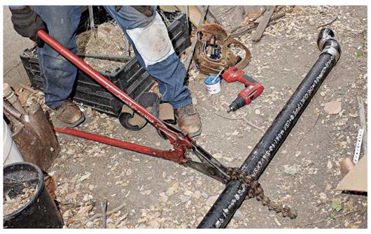
Before cutting into cast iron, however, sup­port the pipe on both sides of the intended cut to prevent movement, which could weaken joints. Use stack clamps (riser clamps), if you’re cutting into a vertical section of pipe. Use strap hangers (see the top photo on p. 277) if cutting into a hor­izontal section. Mark cut-lines on the cast iron with a grease pencil. Then wrap the snap-cutter’s chain about the pipe, gradually tightening till the chain is snug and the tool’s cutting wheels align over the cut-lines. Crank the cutter’s handle to continue tightening the chain till the pipe snaps
cleanly. Make the second cut, and remove the old pipe section. Caution: Wear goggles during this operation.

Once the cuts are complete, slide the neo­prene sleeve of a no-hub coupling over each remaining pipe end. You may need to roll each sleeve back on itself, as you would roll up the cuffs of a long-sleeved shirt. Insert the transition fitting or replacement pipe section, unroll the neoprene sleeves onto the fitting or pipe, and then tighten the steel band clamps. You can also tie into a cast-iron drain without cutting into it, by building out from an existing cleanout, as shown in "Extending a Cast-Iron Main Drain,” on p. 286.

Working with DWV Materials

As mentioned earlier, DWVstands for drainage, waste, and venting. ABS and PVC plastic pipe are by far the most common DWV materials, although cast-iron is still specified where sound suppression is important. Plastic pipe is strong, the most corrosion resistant of any DWV pipe; is easy to cut and assemble, using special solvent – based cements; is light enough for one person to handle; is reasonably priced; and is extremely slick inside, which ensures a good flow of wastes. It’s by far the favorite DWV material of amateur plumbers—and many pros. But there are few disadvantages. Many codes prohibit using plastic pipe on exteriors because of durability and UV degradation issues, and if you don’t spread the cement evenly or allow it to cure before stressing the joints, plastic can leak.

Cast iron is relatively corrosion resistant, though it will rust in time (decades); and its mass deadens the sound of running water. Though it’s heavy to work with, it is still specified by many professionals for high-end jobs, where codes allow pipes on building exteriors, and where codes require cast-iron in multistory buildings. Ever since no-hub couplings replaced lead and oakum, cast iron has been easier to connect, but it still takes skill and strength to cut cleanly and support adequately. Consequently, it’s rarely installed by amateur plumbers. Professionally

DWV Fitting Sampler

ELBOWS

TEES OR TEE FITTINGS

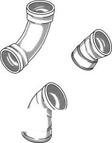
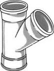
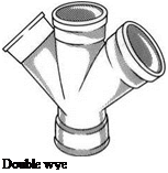
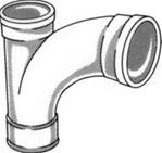
Подпись: Ell or 90image557Подпись: Vent ell Подпись: Long-sweep ellПодпись: 45° ell or 45Подпись: 22’/2-degree ellimage559Подпись:image560Подпись:image561image562"Подпись: Vent tee Подпись: Reducing tee Подпись:Подпись: Double tee or cross fittingПодпись: WYE FITTINGSПодпись: Wye fittingimage565Подпись: Double wye Подпись: POTPOURRI OF PARTSПодпись:image567Подпись:image568image569"Подпись: Trap adapter has a slip-nut coupling with a plastic washerПодпись:Подпись: Cleanout plugimage570Подпись: Closet flange, which glues to a closet bendПодпись: Coupling

The fittings shown are ABS plastic, but their shapes are essentially the same as those of copper and cast-iron DWV fittings of the same name. Drain fittings-such as the long-sweep ell, the combo and the sanitary tee-turn gradually so wastes can flow freely, without clogging. Whereas vent fittings have tighter turning radii because they carry only air. Finally, street fittings have one hubless end that fits directly into the hub of another fitting, which is useful when space is tight.

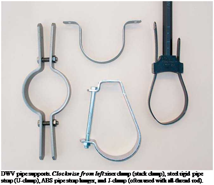
Подпись: DWV pipe supports. Clockwise from left:riser clamp (stack clamp), steel rigid pipe strap (U-clamp), ABS pipe strap hanger, and J-clamp (often used with all-thread rod). image573

Подпись: PRO"ГIP Have a friend help you set plastic DWV pipe. Although plastic is light, it is cumbersome. Once you've applied pipe cement, you have about 30 seconds to position the fittings before it sets. With two people working, one can hold a fitting while the other pushes the pipe and twists it one-quarter turn. 1111

installed cast-iron systems cost, on average,

30 percent to 50 percent more than plastic pipe installations.

Copper DWV pipe is installed mostly on jobs with bottomless budgets. Copper is lightweight, durable, and undeniably handsome. Because its walls are relatively thin, copper DWV pipe is sometimes specified where there are tight turns. However, copper costs two to three times as much as a plastic DWV installation, and it’s less corro­sion resistant. Compared to cast iron, copper’s thin walls don’t suppress sound nearly as well.

PLASTIC DWV PIPE

Cut ABS or PVC pipe with a plastic-pipe saw and a miter box, or with a wide-roll pipe cutter. If you use a cutter, gradually tighten its cutting wheel after each revolution. Whatever tool you use to cut the pipe, use a utility knife, a rounded file, or a deburring tool to clean off burrs before sanding the cut lightly with emery paper. Use a clean cloth to wipe off any grit.

Dry-fit the pipes and fittings before cementing them together. Dry-fitting allows you to deter­mine the exact direction you want the fitting to point, as well as the depth of the pipe’s seat in the fitting. Pipe cement sets so quickly that there’s no time to fine-tune fitting locations. Use a grease pencil or a builder’s crayon to draw alignment marks on the pipe and the fitting; a yellow or white grease pencil works well on black ABS pipe.

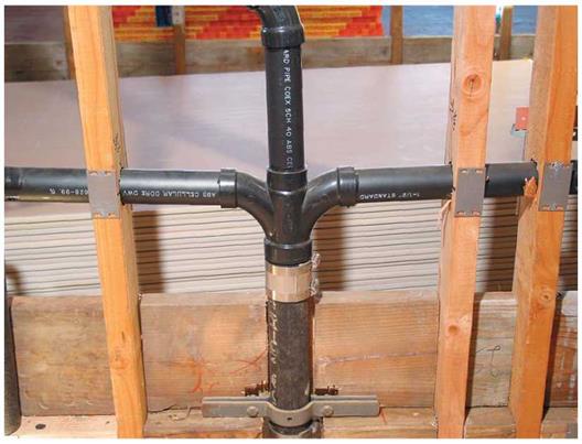
Here, two horizontal ABS lavatory drains meet at a figure-5 fitting, also called a double­combo. An ABS vent rises out the fitting’s top hub, while the drain hub connects to a cast – iron stack via a no-hub coupling. A riser clamp supports the bottom of the cast-iron pipe, and steel nail plates protect the ABS.

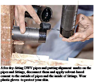
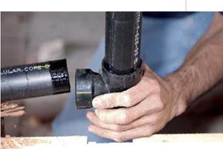
Подпись: Don't use ABS cement on PVC pipe or vice versa. Because solvent-based cements partially dissolve plastic to create a chemical weld, their chemistry is quite specific. Using an incorrect cement or joining PVC and ABS pipe is a code violation because it can lead to weak joints and leaks. llll Подпись: After dry-fitting DWV pipes and putting alignment marks on the pipes and fittings, disconnect them and apply solvent-based cement to the outside of pipes and the inside of fittings. Wear plastic gloves to protect your skin. Подпись: Insert cemented plastic pipes all the way into the fitting and give a quarter turn to spread the cement evenly. The yellow crayon lines are the alignment marks. image575

(See "Pipe Fitting,” on p. 273). Then take apart the dry-fit pieces and apply the cement.

Apply plastic-pipe primer to the outside of the pipe and to the inside of the fitting. Then, using the cement applicator, apply a generous amount of solvent-based cement to the outside of the pipe and the inside of the fitting hub. Immediately insert the pipe into the fitting so that it seats completely. Then turn the fitting (or the pipe) a quarter turn in one direction only—stop when the alignment marks meet. When you are finished, the joint should have an even bead of cement all around. Allow the joint to set completely before putting pressure on it.

One-coat, no-primer plastic-pipe cements are new to the market: They seem promising but as yet are unproven for the long haul. Research them carefully before you commit.

CAST IRON

To the inexperienced eye, all cast iron looks the same, but it’s not. If you lightly rap most cast iron with a rubberized tool handle, you’ll hear a muf­fled thud; old "light iron,” however, will reverber­ate somewhat, with a higher, tinny tone. If you suspect that you have light iron, which was widely installed in the northeastern United States till the 1940s, hire a plumber to assess and possibly cut it for you. If you try to cut light iron with a conventional snap cutter, the pipe may crush and collapse.

To cut into cast iron to extend a DWV system or replace a corroded fitting, rent a snap cutter. Many cast-iron joints are hubbed, in which a straight pipe end fits into the flared hub. But increasingly, sections of straight pipe are joined

A cast-iron snap cutter has beveled cutting wheels along the length of its chain.


image576