Category CARPENTRY

AND TRIMMERS

Now it’s time to cut some of the parts that make up the wall, beginning with the window and door headers and the rough sills. Recall from Chapter 3 that headers are needed at window and door openings to transfer the load of the building around these elements to the foundation. This wasn’t always done in old houses, so walls often
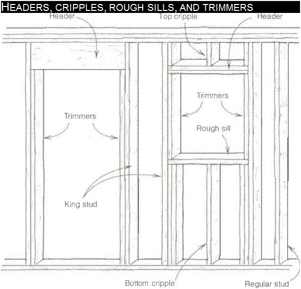
Подпись: HEADERS, CRIPPLES, ROUGH SILLS, AND TRIMMERS

sagged and doors and windows became hard to open because of all the weight put on them. Frequently, part of a remodeler’s job is to open up old walls and cut in solid headers over every door and window.

Ordinarily, the distance from the floor to the bottom of the door or window header is б ft. 10 in. Cripple studs (called cripples) are used to fill in the short space between the top of the header and the top plate, or between the bottom of a window opening and the bottom plate. Trimmer studs (called trimmers), nailed to the inside of the studs that border each end of headers, support the headers at the correct height (see the drawing above).

Cutting headers and rough sills

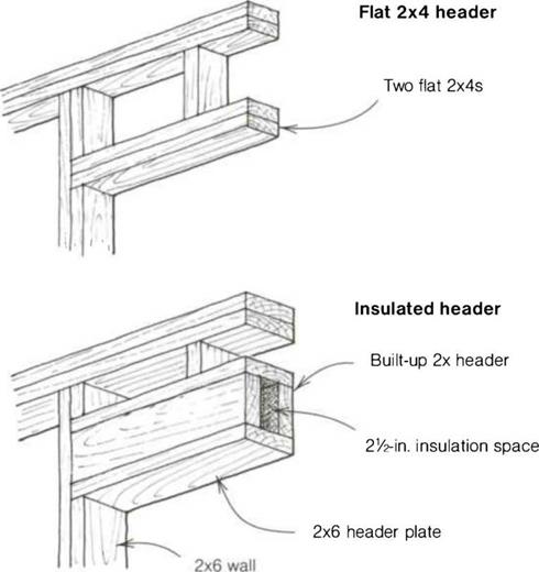
There are different types of headers for different applications. Solid headers (typically a 4×4 or a 4×6) are sometimes used, but more often than not, the headers are built up by sandwiching У2-ІП. plywood between a couple of 2xs. Flat 2x headers can be used for openings in nonbearing walls. Some builders like to put in double flat headers to make sure they have solid nailing for door and window trim. Or you can make a box header that can be filled with insulation to guard against heat loss (see the draw­ing on p. 108).

Outside walls are normally considered to be weight-bearing walls. Interior walls can be bearing or nonbearing, depend-

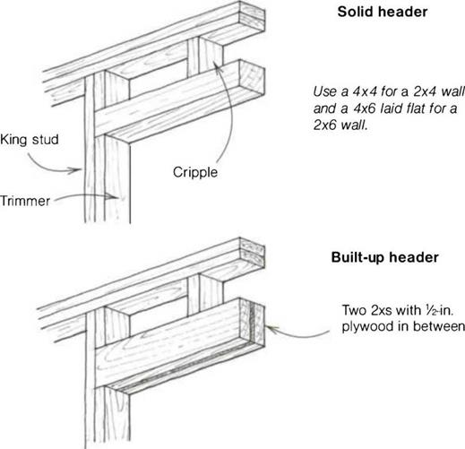
Подпись: FOUR TYPES OF HEADERSAND TRIMMERSAND TRIMMERSing on whether they carry weight from above. If you are using manufactured trusses for the roof, all interior walls are usually nonbearing, which makes it pos­sible to use the flat 2x for interior headers. In houses without roof trusses, joists and even roofs might be supported by an interior wall. Such walls are bear­ing walls and need larger headers to support the weight.

I’m often called on to remove a wall to make a room larger, so it’s important to know about bearing walls. The easiest way to check if a wall is bearing weight is to look in the attic to see whether joists or roof rafters are supported by it. Most walls can be removed, but a bear­ing wall must be replaced with a beam to support the weight. Of course, another owner may come along later who wants smaller rooms, making work for the next generation of carpenters.

The standard length of a header for doors and windows is 5 in. over the rough-opening size. Thus the header for a З-ft. opening is 41 in. The extra 5 in. leaves 3 in. for a 1 Уг-іп. trimmer on each side, 1Уг in. for а 3/нп. jamb on each side, plus 14 in. to plumb the trimmers. When using prehung doors, cut the headers 51Л in. longer for greater ease in installing the jamb.

Rough-opening sizes for aluminum and vinyl-clad window frames generally are 3 in. wider than the rough-opening size of the window. So, for a 3/6 window, cut the header 45 in. long. The extra 3 in. leaves space for a 1 Уг-іп. trimmer on each side plus enough room to set the window. Window frames are actu­ally У2 in. smaller than their nominal size. So a 3/6 window, for example, is usually 3 ft. 51/2 in. wide. Once set in the rough opening, the frame is nailed on with a 1/4-in. clearance on all sides. This gap is closed in by drywall or wood trim. Rough windowsills are cut to the same length as the corresponding header.

Interior walls

Once the exterior wall lines are accu­rately in place, you can measure off them to get the location of interior walls. Just keep an eye on the plans to get the dimensions right.

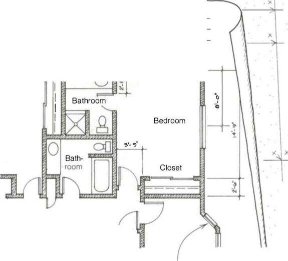
Laying out the long interior walls next makes it easier to locate and mark all the short, 2×4 walls that make up closets and bathrooms. Watch the floor plan. It may show that an interior bedroom wall is 12 ft. 7 in. from the outside of the building to the center of the 2×4 wall. Because half of ЗУ2 in. is 13A in., add 13/д in. to 12 ft. 7 in. to get the overall dimension of this wall, which is 12 ft.

83/д in. from outside to outside.

Measure in this distance from the out­side of the exterior wall of the slab or floor deck, mark it, and place an X to the inside of the mark, as shown in the drawing on the facing page. Do this at both ends of the wall and connect the marks with a chalkline. The location of the X is important because it indicates the exact location of the wall. Placing the X on the wrong side of the mark can be disastrous. Imagine the excite­ment of a plumber, for example, trying to install a bathtub in a room that is ЗУ2 in. too narrow.

You might find that plans don’t always have the exact measurements you need. For example, floor plans might show a 60-in. dimension in a bathroom to accommodate a standard-size bathtub.

In reality, what is needed is 601Л in. so that the tub will actually fit without hav­ing to carve up the walls. And because
of the size of plumbing drains and vents, it’s best to build bathroom walls out of 2x6s to accommodate the plumbing.

PLATING

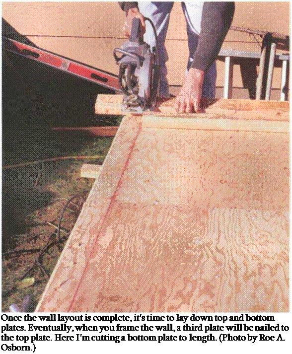
Once you’re finished with the wall – layout chalklines, you can begin to lay down the top and bottom plates. Eventually, when you frame the wall, a third plate will be nailed to the top plate to hold the walls together. At times, when doing remodeling work, I have opened up a wall to find that only a sin­gle top plate was used. This allowed the walls to separate, opening up cracks in the plaster and siding, because they were not tied together with the double top plate.

Pick long, straight stock for plates, which makes it easier to keep walls straight once they’re raised upright.

Plate the long outside walls (called

Подпись:through walls) first. Shorter walls that intersect the through walls are called butt walls. These can be plated once the through walls are in place. Get the long borders of a house in place, and the shorter inside pieces fit together easier.

Placing and securing plates

Remember that top and bottom wall plates are placed flush with the chalk­lines on the X side of the marks made on the deck. But these plates need to be cut accurately or the walls won’t end up square and plumb. Again, begin with the outside walls. Lay down a long 2x plate on the chalkline, cut it to length,
and tack it in place with two or three 8d nails. Run your plates continuously, ignoring door and window openings.

The bottom plate in doorways will be cut out later.

Plating on a slab

Plating on a concrete slab requires a slightly different approach than plating on a wooden floor system. Slabs nor­mally have anchor bolts located around the perimeter to hold the exterior walls in place. On interior walls, the plates are held in position by a hardened screw or nail or by actually shooting a steel pin through them into the con­crete. However you do it, you can’t easily tack the plates in place like you can on a wooden deck. Just position the bottom plate on the line and tack the top plate to it.

Don’t forget to use pressure-treated wood for plates that are in direct contact with concrete. Anyone who has done remodeling work can tell stories of termite-ridden sills or plates made of untreated lumber. If termites get by the sills or plates, they start eating toward the attic. That’s why, in Hawaii (home to the mother of all termites), entire frames are often made of treated wood.

Where there are anchor bolts, their location can be marked on the plate in the same manner as with sill plates (see Chapter 4).

WALLS AN! CE I..IN SS

The first house I helped build was in 1948, on the high plains of western Nebraska. It was a precut house, shipped by rail and brought to the job site on a large wagon pulled by a team of horses. Every piece of wood—wall plates, studs, headers, cripple studs, sills, braces, and joists—was wrapped and labeled in color-coded bundles. Putting the house together was like putting together a three-dimensional jigsaw puzzle.

Houses are still puzzles. All the different pieces have to be laid out, cut, and nailed together to create the frame. The sheathed floor or concrete slab acts as the "table" on which all the puzzle pieces are assembled. But puzzles go together easier when you have an idea of what the finished product will look like. So before pounding the first nail, study the plans thoroughly and develop a picture of the house in your mind.

LAYING OUT WALLS

Framing walls is a challenging task for a beginning carpenter (see the photo on the facing page). The first steps—laying out the location of every wall and snap­ping chalklines to transfer the floor-plan dimensions to the slab or subfloor—are critical (see the drawing on p. 104). Once the house is framed, these wall – layout lines become bedrooms, bath­rooms, and kitchens. If walls are out of square or not parallel, cabinets won’t fit properly, floor tiles will have to be cut, and even the roof ridge may run downhill. At this point, accuracy is more important than speed.

Exterior walls

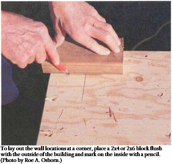
Before you get out your tape measure or chalkline, sweep the floor to get the deck clean for the layout. Start by snap­ping the location of two long exterior walls that are at right angles to each other. Get these two long walls laid out right, and you can measure the location of all the other walls off them. Once you pick a wall, measure in ЗУ2 in. for 2×4 construction or 5У2 in. for 2×6 construc­tion. Then mark the slab or subfloor with a carpenter’s pencil or keel exactly where the wall will stand. Or you can lay a short piece of 2×4 or 2×6 at both ends and mark the inside (see the photo on p. 105). Connect these two marks with a chalkline. Keep it all clear and simple; don’t complicate the puzzle.

After snapping a chalkline for the first wall, lay out the perpendicular wall.

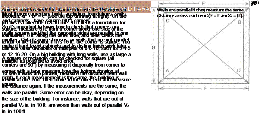
Be sure to check that the walls are perpendicular, especially if you’re work­ing on concrete. Don’t trust that a slab is square. Instead, use the 6-8-10 method (see p. 87) to check for accuracy.

Подпись: Once walls are laid out and plated, they are assembled piece by piece on the floor. Sometimes the studs are marked and cut to length in place. (Photo by Roger Turk.)
As you lay out the remaining exterior walls, note that their dimensions are often given from outside to outside. Look closely to see whether a measure­ment is from outside to outside, outside to center, center to center, or wall to wall.

You don’t have to strive for total perfec­tion when building the house frame. It’s okay to leave walls a tiny bit out of par­allel (like A in. in 12 ft.). But walls out of parallel by V2 in. in 12 ft., for example, need adjusting. To do this, go to one end of the floor or slab and measure in

Bathroom

xI ‘

/

Jf— X –

2*C, Я

Exterior wall


/


Bedroom


7


/


X I A


– Bathroom


Closet


WALLS AN! CE I..IN SS

Подпись: </Подпись: <=,4-'- о1Подпись: уПодпись: Plan drawingПодпись: Exterior wallWALLS AN! CE I..IN SSWalls laid out
on. deck

Keep a close eye on the plan as you lay out first exterior walls and then interior walls. For instance, if the plan shows an interior wall is 12 ft. 7 in. from the outside of an exterior wall, remember to add 13/4 in. to the dimen­sion of the interior walls, which will be 12 ft. 8% in. from outside to outside.

Подпись:

35/s in. at both corners. This increases the width by Va in. Then go to the other end and measure in 33/s in. at each cor­ner. This narrows the width by Va in. The walls are now parallel. At this point, there is no need to pay attention to door or window locations.

Nail buggy

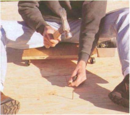
Подпись: Sitting on a nail buggy makes it easier to nail floor sheathing. (Photo by Roe A. Osborn.)Nail buggyA nail buggy is a good tool when you have to nail subfloor by hand. Better to nail sitting on your bot­tom than crawling on your knees. Cut a 20-in. circle or square from 3A-in. plywood. Buy three or four good wheels at least 2 in. in diameter and screw them to the bottom of the plywood. Attach a bread pan to the side to hold nails. Now, like an Olympic swimmer doing laps, you can sit on the buggy and push yourself backward as you nail down subfloor. Just don’t roll off the edge of the floor.
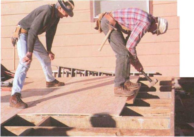
Подпись: Sometimes T&G plywood needs some not-so-gentle persuasion. Have one person stand on the sheet to hold it flat and snug against the previous row while another hits it with a sledgehammer. The 2x placed in front of the sheet protects the plywood edge from damage. (Photo by Roe A. Osborn.)Nail buggy

from damage) and hits it with a sledge­hammer (see the photo at right). A couple of licks should bring the two sheets together.

Once you have all the sheets tacked in place, you can move around the floor driving nails to secure the sheathing to the joists firmly. (A nail buggy will make this job easier; see the sidebar above.)

A typical nailing schedule would be to drive 8d nails 4 in. o. c. on the perimeter (around the outside), б in. o. c. near joints, and 12 in. o. c. in the field (in the middle of the sheets). You may want to use ring-shank nails for better holding power.

Drive the nails straight into the center of the joists. While some carpenters snap a chalkline as a nailing guide across each sheet, try nailing by eye. When you feel that you have missed a joist, stop, pull the nail, and drive another.

Extra joists and headouts

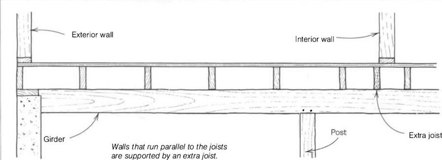
Extra joists are needed under parallel walls (walls that aren’t perpendicular to the floor joists) to carry the added weight that gets transferred down through these walls. Move the extra joists away from the center of each
parallel wall about 3 in. to allow room for pipes and conduit to be run up into the walls from below (see the draw­ing above).

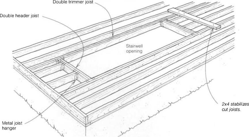
Sometimes joists must be cut to allow room for a stairway, access to an attic, a place to install a skylight, or even for a heater vent in a wall or a tub trap in a bathroom. Carpenters call these open­ings headouts (see the drawing on p. 98). Regular 2x joists (not I-joists) can be cut as long as they are sup­ported by a header joist and fastened to parallel joists. Here are some basic rules for headouts:

• If more than one joist is cut, double the header joist and side joists.

• Support cut joists temporarily by nail­ing a flat 2x across their tops.

• Nail 16ds through the header joists into the cutoff joists.

• Support both header and cutoff joists with metal joist hangers at intersecting points.

Extra joists and headouts
Nail double joists together with 16ds at 1 б in. o. c.

• Keep all wood at least 1 in from heat­ing vents.

• A common mistake made by carpen­ters framing a headout is to forget to leave room for the header joists. If, for example, a 6-ft.-long floor opening is needed, cut it б ft б in. This leaves room for a double header joist at each end.

SHEATHING THE FLOOR

Once floor framing is complete, it’s time to cover it with sheathing. Although it’s easier to install rough plumbing and heating ductwork now, this can be done after the subfloor has been laid. After the sheathing is nailed in place, you’ll have a level platform, perfect for build­ing a house or for having a dance!

Normally floors are sheathed with 4×8 sheets of 5/s-in. or 3/4-in. tongue-and – groove (T&G) plywood or OSB. The sheathing should be exterior grade so that it won’t come unglued when exposed to moisture. While square- edged sheathing can be used, codes often require it to be supported by edge blocking between joists. The edges of T&G sheathing are self-supporting and don’t require blocking.

Floor sheathing is bulky and awkward and in windy conditions can act like the sail of a windsurfer. So be mindful when handling it. Also, T&G plywood should be handled with care so you don’t wind up with damaged edges, which can make it hard to fit two sheets together. When I carry sheathing, I grasp it with one hand underneath and one on top

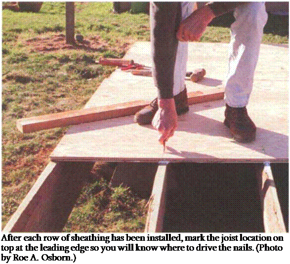
Подпись: Construction adhesive helps secure sheathing tight to the joists and reduce floor squeaks. Place a У4-ІП. bead on each joist. (Photo by Roe A. Osborn.) Подпись: After each row of sheathing has been installed, mark the joist location on top at the leading edge so you will know where to drive the nails. (Photo by Roe A. Osborn.)

for balance, allowing much of the weight to rest against my upper body.

Or I get a helper.

Sheathing is installed so that the 8-ft. edges are perpendicular to the floor joists. Before laying any sheathing down, though, first measure in 481Л in. from each end and snap a chalkline across the joists between these two marks. This line acts as a control, or reference, line for the first row of sheathing, and the extra 1/4 in. allows for any slight variation in the rim-joist alignment. With the first row of sheathing straight, the rest of the job will be easier.

Fastening down the sheathing

It’s a good idea to lay down a bead of construction adhesive on each joist before installing the sheathing. The adhesive secures the sheathing tight to the floor joists and helps prevent or reduce floor squeaks, which happen when joists dry out and shrink away from the subfloor. Apply а Ул-т. bead to each joist over a section large enough to lay down a 4×8 piece of sheathing (see the top photo at right).

Lay the first sheet with the grooved edge right along the control line with each end hitting along the center of a joist. If the plywood edge doesn’t fall on a joist, snap a chalkline and cut the sheet to length so that it breaks on the center of the joist. Set the circular saw to the proper depth (% in.) and make the cut. Don’t leave the cutoffs under the floor, or you’ll give termites an easy meal.

Tack down the sheet to the joists with one 8d nail near each corner. On large floors, nail off the sheets after you have laid four or five; otherwise, the adhesive could set up (especially in hot weather). Be careful not to drive nails within 6 in. of the leading edge, because you’ll need

Floor joists

Extra joists and headouts


a little flexibility here to make it easier to mate the groove of the first row with the tongue of the next

After placing a row of sheathing, mark the location of every joist with a pencil or keel on the leading edge of the sheathing (see the bottom photo on p. 99). This will make it easy to find the joists when you start nailing all the sheets down.

If you live in a wet climate, leave about Vs in. between the ends and edges of the sheets to allow for expansion. This gap can be gauged by eye or by using an 8d nail as a spacer.

Don’t install sheets so that four corners meet at the same point. Instead, stagger the plywood joints, as a bricklayer would do when building a chimney, to add strength to the floor (see the drawing above). Begin the second row with a 4-ft. by 4-ft. sheet, and install it adjacent to the 8-ft. sheet in the first row. Then complete the row with 8-ft. sheets.

Sometimes a little extra persuasion is needed to unite T&G plywood. One way to do this is for one person to stand on the sheet, holding it flat and snug against the previous row of sheathing. The second person places a scrap 2x against the edge (to protect the edge

Floor system

Floor system

support has been determined by tests and incorporated into building codes.

All you need to do is check your plans to see what type and size of joists you’ll use.

Joist size is usually determined by the distance they have to span. So the larger the span, the larger the joist. When you are joisting over a basement with a sin­gle center support, you often use 2x12s. If you are joisting over a crawl space with girders every б ft. or so, you can usually use 2x6s. Now with I-joists, you can span from sill plate to sill plate with­out any support in the middle. Floor joists on the first floor may be a different size than those used on the second floor.

Whatever size or type of joist you use, nailing them in place is more or less the same for big or little.

Layout

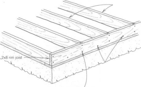
Once the sill plates are securely in place, the next step in joisting a floor is to lay out locations where joists are actually nailed in place. I like to do my layout on the rim joists (also called band joists). Rim joists are nailed into the sill plates around the perimeter of the building and help hold the floor joists upright.

I nail the rim joists onto the outer edge of the sill plate with 16d sinkers toe – nailed every 16 in. o. c. Use galvanized or stainless-steel nails in wet climates or near the ocean.

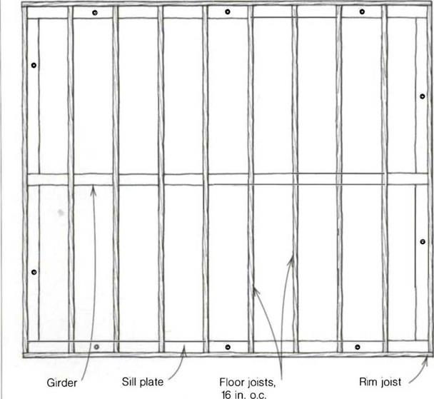
Once the rim joists have been toenailed in place, lay out the floor-joist locations on them. Joists are most often spaced 16 in. o. c. so that they can be efficiently sheathed with 4×8 sheets of plywood or oriented strand board (OSB), but check the plans to make sure. Manufactured joists are sometimes spaced at 19.2 in. This layout also fits a piece of 8-ft. sheathing. Hook a long tape measure on the end of the rim joist and make a mark on top of the rim every 1 б in.

(16 in., 32 in., 48 in., etc.), down its entire length. Put an X or straight line alongside each mark to show on which side of the line the joist will be nailed (see the drawing at right).

If the joists span from rim joist to rim joist, the layout will be the same on each rim joist. If the joists lap over a girder or wall, the opposing rim joists need to be laid out differently. On one rim joist, mark the 16-in. o. c. locations with an X to the right; on the opposite wall, lay out the joists with an X to the left. This will allow the joists to lap and nail at a girder, where they will be stabilized with nailed-on blocks.

Once the layout is complete, lay all of the floor joists flat across the sill plates and girders on every layout mark. Keep your eye open for joists that are badly bowed or twisted or those with large knots. These should be replaced with better stock and set aside to be cut up for blocks later. If joists need to be cut, cut them in place rather than measure each one individually (see the photo on p. 94). Just remember not to notch or cut I-joists in midspan, which compro­mises their structural integrity.

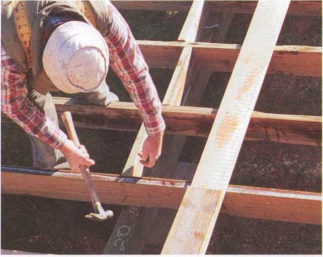
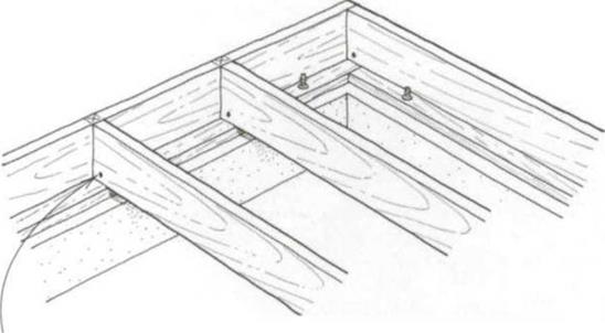
Floor systemOnce the joists are cut to length, it’s time to "roll" them. Rolling means to set floor joists on edge and nail them in place with their crown (the slight bow along the bearing edge) up. Line up each joist with the layout marks on the
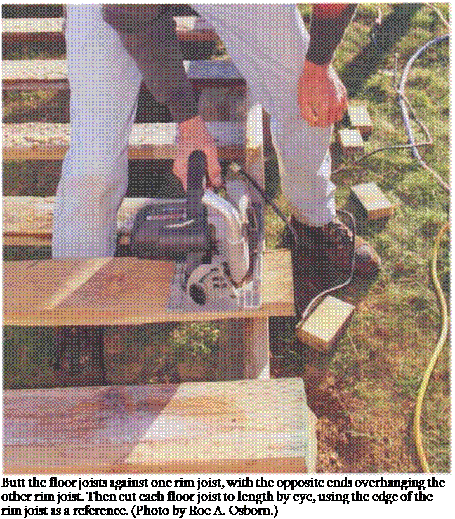
Подпись: Butt the floor joists against one rim joist, with the opposite ends overhanging the other rim joist. Then cut each floor joist to length by eye, using the edge of the rim joist as a reference. (Photo by Roe A. Osborn.)
top of each rim joist, making sure the floor joist is snug against the rim. Then drive two 16d nails through the rim joist directly into the end of each floor joist— one nail at the top and one at the bottom (see the drawing on the facing page).

Make sure you nail all joists and blocks securely as they are installed. Someone stepping on an unnailed 2x could slip and fall. Also, don’t leave nails half – driven, and don’t drive nails where you might have to make a saw cut later on. Take time to do good, clean work. If
using a pneumatic nailer, drive the bot­tom nail first, then remove the hand holding the joist and drive the top nail. I can promise that if you drive the top nail first, sooner or later you will miss the wood and fire a nail into your hand.

Each floor joist also needs to be toe – nailed to the sill plates and supporting girders. Try walking one way, driving a 16d toenail through each joist into the sill plate or girder. When you reach the end, turn around and repeat the process on the other side of each joist.

2×8 floor joists


Toenail the rim joist into the sill plate using 16d galvanized nails spaced 16 in. o. c.


Drive two 16d galvanized nails through the rim joist into each floor joist.


Toenail each floor joist to the sill plate on both sides using 16d nails


Floor systemFloor system

After nailing in the floor joists, I like to stop and look at my work. Joists on edge portray a certain symmetry and beauty. They clearly show the outline of the building.

Blocking

Blocking helps stabilize a building and keeps joists from falling like dominoes under stress, such as might happen dur­

ing an earthquake or high wind storm.

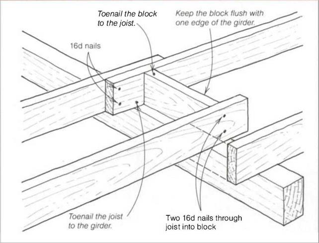
If floor joists are spaced 1 б in. o. c., cut blocks 141/2 in. long. If you are blocking lapped joists, cut them 13 in. long (see the drawing on p. 96). I find that blocks need to be cut just a bit under their actual size (cut а 14Уг-in. block at 147/i6 in.). I think this is because 2x lum­ber is frequently wet and measures just a bit more than 1 Vi in.

Floor system

Floor system

When installing blocks between floor joists, set each one on edge and drive two 16d nails through the joists into the block. Offset each block to one side of the previous block. (Photo by Roe A. Osborn.)

Floor systemFloor system

Be careful to start correctly. Begin by set­ting a block on edge between the rim joist and the first floor joist over a girder or bearing wall. Nail it in place with two 16d nails through the rim joist into the block and with one 16d nail through the floor joist into the block. Next, angle a 16d toenail through both sides of the joist into the center girder. Grab another block, offset it to one side of the previ­ous block, and repeat the nailing process (see the photo on the facing page).

Once you have a few blocks nailed in place, use your tape measure to check for accuracy. The floor joists will be straight if they maintain the same on – center layout (16 in., 32 in., 48 in.) over the girder as they do at the rim joist. If the blocks are too long or too short, the floor joists will be curved rather than straight.

Toenailing

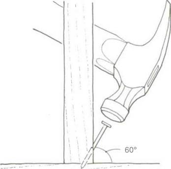
Carpenters need to know how to drive a nail at an angle. This technique is called toenailing and is often used to join pieces of wood that meet at a right angle.

When toenailing, you have to be careful not to split the wood, which is easy to do when you’re nailing so close to the end of a board. You can often avoid splitting the wood by dulling the point of the nail. Place the nail head on a hard surface and tap the point several times with your hammer. In­stead of spreading the wood fibers and splitting the wood, the blunt point will simply break the wood grain as it penetrates.

To toenail two boards, hold the nail at a 60° angle and start it about 3A in. from the end of the board that’s perpendicular to the other (or you can start the nail straight in, then pull it up to the correct angle). Then drive it home into the adjoining piece of wood.

Toenailing

Toenailing

Bracing and splicing girders


Toenailing

SUPPORTING FLOOR JOISTS

It’s common in many regions to build houses directly on a concrete slab. When this is the case, wall building can begin once the sill plates are down. Other builders use a system of posts and girders to support joists so that a floor can be nailed to them. Still others use manufac­tured joists (called I-joists) that span a basement from sill plate to sill plate without any interior support, leaving a room large enough for a dance hall. [7]
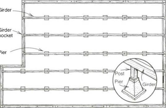
length of the building. Houses fre­quently have an exterior stemwall foundation with girders supported by piers set on concrete footings (see the drawing above).

Post length

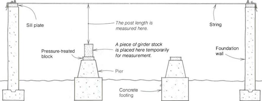
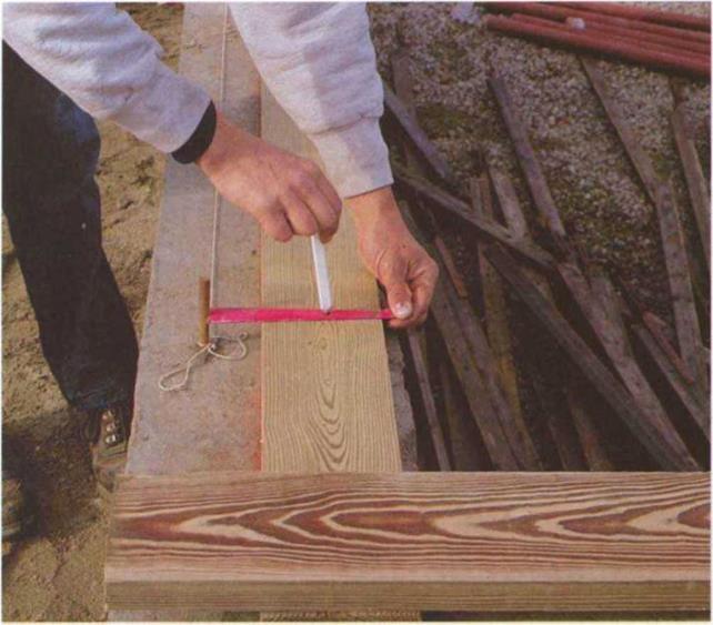
Posts in a basement will be quite long, while posts in a crawl space will be shorter—only about 1 ft. to 2 ft. But to keep wood dry and away from termites, make sure that no wood is within 6 in. of the ground. To determine the exact length of each post, pull a chalkline directly over the tops of the concrete piers that will support them, from foun­dation wall to foundation wall (see the top drawing on p. 91). Then place a scrap piece of girder stock (like a 4×6) on a pier. The distance between the string and the top of the girder stock is the length of the post for that pier. Make a list and note the length of every post before beginning to cut them.

Posts are usually cut from 4×4 stock. In some areas, they may need to be pres­sure treated. They can be cut to length with a circular saw or with a chopsaw. Leave the string in place to help align the posts as you nail them to the top of the piers. Toenail three 16d nails (two on one side, one on the opposite side)—or four 8d nails—down through the post into the wooden block on top of the pier (for more on toenailing, see the sidebar below).

Girders

Once the posts are nailed in place, it’s time to cut and nail on girders. Again, use straight stock that isn’t twisted. Pier posts are often 6 ft. apart, so cut the girders to break in the middle of a post, which will ensure solid bearing for all girders. Secure the girders to the posts with three 16d or four 8d nails. Take some simple steps to strengthen the
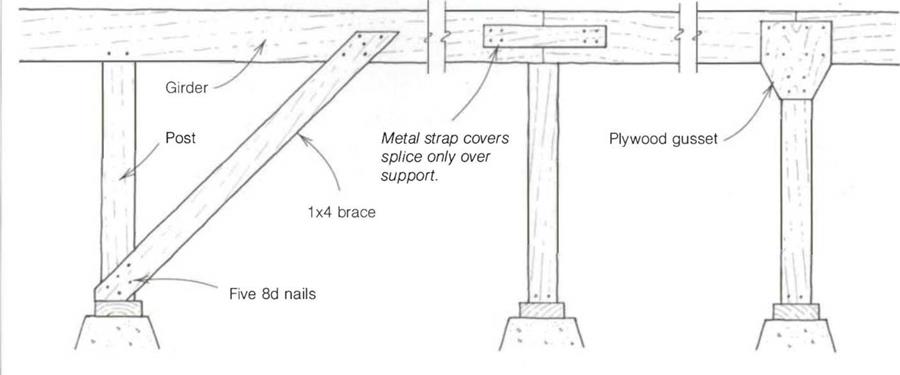
girder frame structurally, especially if you live in earthquake country: If the posts are over 3 ft. long, nail a 1x brace diago­nally (45°) from the bottom of the post to the girder with five 8d nails in each end (see the bottom drawing on the facing page). Unite the joints with a metal strap or a plywood gusset. I prefer the gusset because it ties girder to girder and girders to the post.

INSTALLING JOISTS

Joists are placed on edge across the sill plates to provide support and a nailing surface for the subfloor and a platform for the walls (see the drawing on p. 92). The joists need to be strong enough to support your grand piano without having it wind up in the basement.

Joist systems are made from either stan­dard 2x lumber or from manufactured joists. The weight these members can

CUTTING, MARKING, AND DRILLING SILL PLATES

Just as you must follow rules when play­ing sports, there are rules—or building codes—to follow when building a house. Most codes require that every sill plate have a bolt about 1 ft. from each end and every 4 ft to б ft. between to connect the house frame securely to the foundation. So the edges of the founda­tion and the location of the bolts let you know where cuts in the sill plates should be made.

These cuts can be made by eye if you’re feeling confident in your ability to make a square cut with a power saw.

Remember, sill plates must be placed on the foundation accurately, not perfectly. This is frame carpentry, not finish work.

Sill plates normally are bolted flush to the outside of the foundation. Place the plate directly on the inside of the chalk­line and use a tape measure or a bolt marker to locate where the bolt holes are to be drilled (see the photo below). You can make a simple measuring device to mark bolt holes or buy one from Pairis Enterprises (see Sources on p. 198).

As you become more experienced, try placing the sill plate on top of the bolts and eyeball the edge of the sill flush

CUTTING, MARKING, AND DRILLING SILL PLATES

CUTTING, MARKING, AND DRILLING SILL PLATES

A simple measuring device called a bolt marker can be used to locate the bolt holes. With the sill plate lined up on the inside of the chalkline, hold the end of the marker against the bolt and mark the bolt hole. (Photo by Roe A. Osborn.)


CUTTING, MARKING, AND DRILLING SILL PLATES

with the chalkline or the outside of the building. Hit the sill with a hammer right over each bolt to leave a mark for drilling.

Many tasks you do in carpentry can be done by trusting the eye. Marking bolt holes in a sill plate is an example of this. Carpenters call this "eyeball carpentry." Basically, all it takes to train the eye to see accurately is practice.

With the bolt locations marked, set the sill plates on a block of wood and drill the holes. Use a 5/s-in. or n/i6-in. bit with a power drill to make holes for Уг-іп. bolts. Place the sill plates over the bolts, using your hammer to drive boards onto tight-fitting bolts. Put a washer and a nut on each bolt. Now is the time, if needed, to put pressure-treated shims under the sill plates to make sure they are level. Finish by tightening the nuts with a crescent wrench.

In colder parts of the country, you may want to lay down a thin layer of insula­tion between the sill plates and the foundation. This helps prevent air leaks.

FRAMING FLOORS

When a carpenter first arrives at the job site, the foundation is often poured and ready for sill plates, joists, and floor sheathing. Just make sure you’re building on the right foundation. I once started building on the wrong lot in a tract of houses. My crew was well under way when the owner of the property arrived and said he appreciated our efforts but wasn’t intending to build just yet

CHECKING THE FOUNDATION

Like most things in life—from cooking to marriage—if you get started right, things just seem to go better the whole way. This is certainly true in construc­tion. So before attaching the wooden sill plates to the foundation, you must be sure that the foundation itself is accu­rate. Problems get worse by the day unless you get started square, plumb, and level.

Begin with a visual on-site check. Get down and sight along the foundation. The concrete wall should sight straight and true, with no dips or waves. Next, use your tape measure and level to check for foundation accuracy (see the sidebar on the facing page).

Walls that are out of parallel can be corrected by adjusting the sill-plate chalklines. Say, for example, that the

FRAMING FLOORS

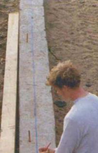
Chalklines on top of the concrete foundation indicate the position of the sill plates. (Photo by Roe A. Osborn.)

walls are out of parallel V2 in. and the sill plates are SV2 in. wide. Go to the narrow end of the foundation and measure in from the outside 35/s in. on each corner. Then go to the wide end and measure in 33/s in. at each corner. By making a small, Vs-in. change at each corner, you

FRAMING FLOORS

gain У2 in. overall, and the walls are now parallel. Pressure-treated shims can be put under the sill plates to bring every­thing up to level.

Once you know the condition of the foundation, take the time to sweep any debris from the concrete walls and to straighten the anchor bolts. Bolts can be
straightened by placing a З-ft. length of Унп. pipe over a tipped bolt and bend­ing it upright. The next step is to snap chalklines on the concrete to mark where the sill plates will be bolted (see the photo on the facing page). Be sure to use straight pressure-treated stock for the sill plates. Set the crooked ones aside to cut up for short walls later.