Category RENOVATION 3

CONNECTING TO FIXTURES

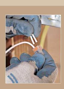
Electrical connections to light or fan fixtures are simple: ground wire pigtail to green screw (if any), hot pigtail to black lead wire or gold screw, and neutral pigtail to white lead wire or silver screw. If fixture lead lines are stranded, cut them a little longer than solid-copper pigtails so that both will seat correctly when they’re spliced with wire nuts. Push-in Wago Wall-Nuts are a good alternative (see "A New Kind of Nut,” on p. 248). Physical connections, such as mounting fixtures

WIRING A RECEPTACLE

image504

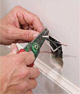
After finish walls are installed and painted, attach the wires to the devices. Start by stripping the wire ends.

image505

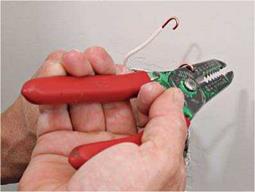
Some wire strippers have a small hole near the handle. Insert a stripped wire, flip your wrist 180 degrees and— voila!—a perfect loop and faster than needle-nose pliers.

to outlet boxes and attaching outlet boxes to framing, are covered on pp. 260-261.

Wiring fixtures quickly gets complicated when three – or four-way switches control fixtures, as you’ll see shortly. If the fixture is a combo—say, a light and fan—each function is usually controlled by a separate switch. Running three-wire cable (for example, 14/3 with ground) to the fixture enables you to run a separate hot wire to both the fan and the light.

INSTALLING SWITCHES

О First, turn off the power. Switches interrupt the flow of current through hot wires only. Neutral wires and ground wires are always con­tinuous, never interrupted. Whether a switch controls a receptacle, fixture, or appliance, hot wires only are attached to switching terminals.

Single-pole switch. A single-pole switch is sim­ple to install. Splice the ground and neutral wire groups as described for receptacles, in the pre­ceding sections. Attach the grounding pigtail to a green grounding screw on the switch, if any. Splice the neutral wires together with a wire nut; they need no pigtail because they don’t attach to switches. Finally, strip h in. of insulation from the ends of the hot wires and attach them to the switch terminals—either by screws or back wiring. It’s customary to install a single-pole switch with the manufacturer’s name at the top, so that the switch toggle will be up when a light is on and down when off.

Bending a cardinal rule. When an outlet box is closer to the power source than to the switch box, a single cable may run to the switch, as shown in "Switch at End of Cable,” on the facing page. Splice the ground and neutral wires from the source; then attach a neutral pigtail to a fixture lead wire. However, the hot wire from the source should not attach to a fixture lead—instead, the


WIRING A SWITCH


image507

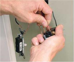
To back-wire switches, first attach the ground wire to the green screw. Then strip the insulated wire ends, using the stripping gauge on the back of the switch. Insert the wires into the terminal holes.


Wiring a Victorian Light Fixture


image508

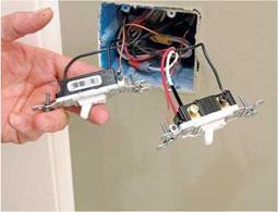
Two types of switches. Left:a single-pole switch; right: a three-way switch. The three-way switch shown has two traveler wires—one red and one white painted black to indicate a hot wire.


image509

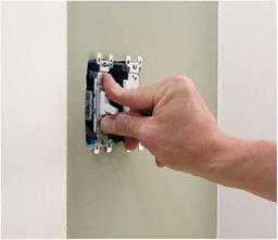
After wiring the switch, push it into the box to prepack its wires and seat it in the position you want. Caution: Don’t be tempted to use box screws to pull the devices in or you’ll end up with crooked devices and stripped screw threads.


image506

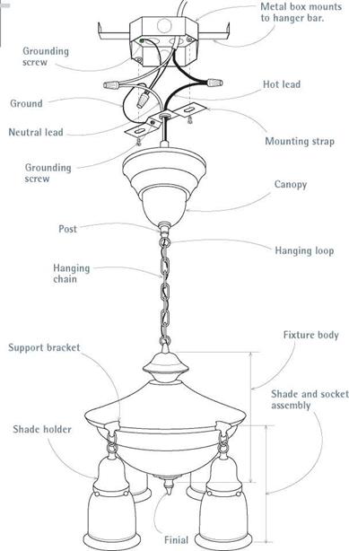
Connecting the incoming wires to fixture leads is standard: hot to hot, neutral to neutral, and splice ground wires. All metal parts should be grounded; if you’re attaching to a metal box, the grounding pigtail to the mounting strap is optional. Note: Fixture bodies and mounting devices vary considerably.
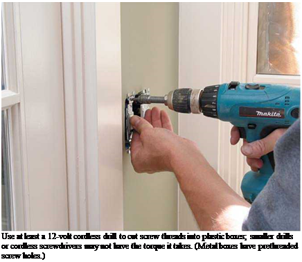
Подпись: Use at least a 12-volt cordless drill to cut screw threads into plastic boxes; smaller drills or cordless screwdrivers may not have the torque it takes. (Metal boxes have prethreaded screw holes.)

incoming hot wire is spliced to a cable wire run­ning to the switch.

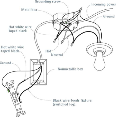
Here, for convenience, we break the rule of using the white wire only as a neutral wire and instead use black tape on each end of the white wire, to show that it is used as a hot wire. At the switch, attach the black wire and the white wire (taped black) to the switch terminals. This allows you to use inexpensive two-wire cable as a switch loop. Thus painting or taping the white wire black is a breach of the rule in letter only, because both wires are technically hot. We have not mixed actual hot and neutral wires.

More complex switches. Switch wiring gets complex when three – and four-way switches require three – or four-wire cable (plus grounds). If you get confused, redraw each configuration, identifying hot wires with an H, neutral wires with an N, and so on. At each splice remind your­self: Neutral wires and ground wires are continu­ous; switches interrupt hot wires.

If switches or light fixtures have green grounding screws, run a pigtail to them from the

Подпись: Switch at End of Cable

image511,image512

Light Fixture at End of Cable

Подпись: Switch-wiring at its simplest: Incoming and outgoing hot wires attach to the terminals of a single-pole switch. Neutrals and ground are continuous.Attach the incoming neutral to a fixture lead; run the hot to a switch at the end of the cable. Use the white wire of a two-wire cable as one of the hot wires attaching to the switch—but tape both ends of the white wire black to show that it’s hot.

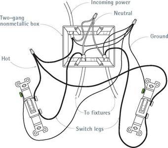
Подпись: I Two Switches, Two Fixturesimage513Подпись: This is a typical setup for switches by exterior doors. For example, one single-pole switch controls an exterior light fixture, while the second switch controls an interior fixture.

Three-Way Switch

image514

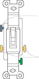
Common (COM) terminal

Traveler wires attach to gold screws.

Three-way switches control power from two locations. Each switch has two gold screws and a black screw (common terminal). The hot wire from the source attaches to the common terminal of the first switch. Traveler wires between the switches attach to the gold screws. Finally, a wire runs from the common terminal of the second switch to the hot lead of the fixture.

ground-wire splice (many older fixtures may not have grounding screws). However, if you’re using metal boxes, they must always be grounded: In this case, loop a pigtail from the ground-wire splice to a green screw attached to the metal box.

Conduit and Flexible Metal Cable

The NEC requires that conductors be protected by conduit or flexible metal cable where conduc­tors are exposed, where conductors run through metal studs (and could get nicked), where high moisture could corrode conductors, and so on. Flexible metal cable has factory-installed conduc­tors (wires). But you need to pull conductors through conduit.

FLEXIBLE METAL CABLE

Flexible metal cable is commonly used in remod­eling, and it satisfies most code requirements. In addition to its use in branch circuits, MC is

INSTALLING A GFCI RECEPTACLE

Important: Read earlier sections about installing standard receptacles before installing a GFCI receptacle. As already mentioned, the NEC requires GFCI protection in the following loca­tions: all bathroom receptacles; all kitchen counter receptacles; kitchen receptacles within 4 ft. of a sink; all outdoor receptacles; accessible basement or garage receptacles; and receptacles near pools, hot tubs, and the like.

О Shut off power to the outlet and test with a voltage tester to be sure it’s off. Carefully read the instructions that come with your GFCI. Devices vary, and your warranty—and your safety — depends on your installing the device correctly. GFCI receptacles are amperage rated (15 amp and 20 amp) and should match the cable wire size and be correctly sized for the circuit load.

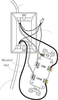
GFCIs are wired in essentially the same man­ner as standard receptacles—hot wires to gold screws, neutral wires to silver screws, ground wire to grounding screw—except here you’ll need to know which incoming cables are line wires (from the power source) and which are load wires (running on to the next outlet). So disconnect the old receptacle while the power is off and separate wires from each other. Temporarily turn the power back on and—being careful not to touch the bare wire ends—use a voltage tester to determine which pair of wires are "line.” That done, turn the power off again and use white tape and a felt – tipped pen to denote "LINE” and "LOAD” wires.

Attach the wires running from the power source to the screw terminals or wire leaders marked "LINE,” attach wires continuing to the next outlet to the terminals or leaders marked "LOAD,” and attach ground wires to the terminal or leader marked "GROUND” and (if it’s a metal box) to the pigtail that grounds the box. If there are no outlets downstream, use wire nuts to cap the two load leaders.

When connections are completed, gently press the device into the outlet box, screw the recepta­cle to the outlet box, install the cover plate, and turn the power back on. Then test the GFCI by pressing its "on”or "test” button, per the manufac­turer’s instructions. If the device won’t stay on or

Подпись: PROTIP Back-wired receptacles have holes in the back, into which you insert stripped wire ends. They're quicker to wire than screw terminals, but the receptacles' internal tension clamps can fatigue, leading to loose wires, flickering lights, and arcing. Moreover, each time you insert and remove plugs, the receptacles move slightly, which increases likelihood of clamp failure. Manufacturers have stopped making back-wired 20-amp receptacles, so think twice about installing 15-amp receptacles. Back-wired switches, on the other hand, rarely fail. 1111

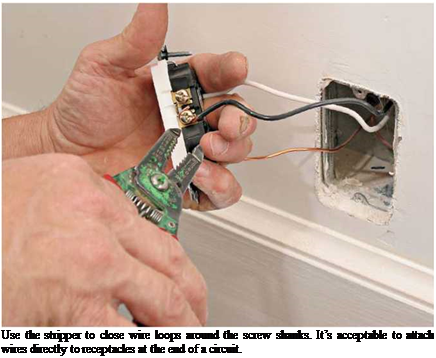
Подпись: Use the stripper to close wire loops around the screw shanks. It’s acceptable to attach wires directly to receptacles at the end of a circuit.

devices downstream don’t work, you have either a short circuit or a defective GFCI. Most makers recommend testing the devices once a month. All GFCI receptacles used outdoors must be housed in gasketed, weatherproof boxes with covers.

Fixtures, and Switches

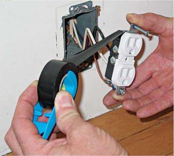
О Before working around any electrical device, disconnect the power to it and test with a voltage tester to make sure the power is off.

WIRING RECEPTACLES

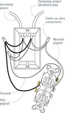
Before beginning this section, read the previous sections on grouping and splicing wire. The fol­lowing discussion assumes that each wire group (hot, neutral, ground) in the box is spliced together and has a pigtail that attaches to a receptacle terminal. Connecting wires and devices in this manner ensures that there will be continuous current to outlets downstream, even if a receptacle upstream malfunctions or is tem­porarily removed.

Method one: Using pigtails. First attach the grounding pigtail to the green grounding screw on the receptacle. If the grounding pigtail is insu­lated, strip ‘A in. of insulation from its end; then use needle-nose pliers or a hole in the wire strip-

A New KIND OF NUT

Splicing with twist-on wire nuts can be problematic. It’s impossible to tell if the wires have come loose as you twist on the nuts; and stranded wire tends to slide down solid wire when you join solid wires to twisted-strand fixture leads. Wago Wall-Nuts™ simplify the task: Strip the wire ends the specified amount, and then push them into nut ports that hold the wires fast. The clear plastic housing allows you to see if the wires are connected, and the ports grasp both stranded and solid wire well.

per handle to loop the end of the pigtail clockwise, as shown in the bottom left photo on p. 25′. Fit the looped wire onto the grounding screw, and then tighten it. (Screws tighten clockwise.) Next strip h in. of insulation from the neutral pigtail, loop it clockwise, and attach it to a silver screw on the receptacle. Finally, strip!2 in. of insulation, then loop and attach the hot pigtail to a gold screw on the opposite side of the receptacle.

When all wires are connected, tighten down any unused screws and gently push the wired receptacle into the outlet box, so the wires fold like an accordion. Make sure that the receptacle

Wiring a Receptacle I in Midcircuit

Note: In the wiring schematics on pp. 248-255, thin, solid lines denote ground wires, white wires denote neutral conductors, and black, red, or slashed wires denote hot conductors-unless otherwise indicated on an illustration.

image498

By splicing like wire groups and running pigtails (short wires) to the receptacle, this conventional method ensures continuous current downstream.

face is flat to the wall plane, not tilted, and the receptacle is centered in the box. Push the recep­tacle into the box by hand: If you use the screws to pull the receptacle into the box, you may strip a screw hole in a plastic box. Later, after the walls have been painted, screw a cover plate to the receptacle.

Method two: Feeding through receptacles.

Rather than splicing like wire groups and run­ning pigtails to the receptacles, you can instead attach hot and neutral wires directly to the recep­tacles. This wiring method—"feeding through receptacles”—is widespread because, on the whole, it is quicker, requires fewer conductors, and results in boxes that are less crowded than those wired with spliced wires and pigtails. It is also acceptable to the NEC.

But feeding wires through receptacles has detractors, who argue that in a circuit so wired, if a receptacle upstream fails or a wire comes loose, receptacles downstream will lose power.

Moreover, there is a voltage drop of about 1 per­cent per receptacle wired in this manner because receptacles offer more resistance to current flow than wire. If you have 6 or 10 receptacles daisy – chained in this manner, those overheated connec­tions can heat up your electricity bill.

However, in older homes with ungrounded outlets, there’s an upside to feeding through receptacles. If you install a GFCI receptacle on the circuit, the GFCI will protect all receptacles downstream. That is, if there’s a ground-fault at a receptacle downstream, the GFCI will cut power to it and therefore make the entire circuit safer.

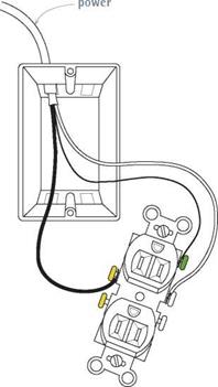
Подпись: PROTiP If you install three-prong receptacles or GFCI receptacles on an ungrounded circuit, the NEC requires that you label affected receptacles "no equip-ment ground." 1111 End of circuit. A receptacle at the end of a cir­cuit has only one cable entering the box and none going beyond it. In this case, it’s acceptable to attach wires directly to the receptacle terminals, without using pigtails. Attach the ground wire to the green ground screw, the neutral wire to a sil­ver screw, the hot wire to a gold screw.

Fixtures, and Switches

Feeding Wires I through Receptacles

Wiring a Receptacle I at End of a Circuit

image499

Incoming

image500


Attaching hot and neutral wires directly to receptacle terminals is quicker and results in a less crowded box. However, with this wiring method, if the receptacle fails, power can be disrupted to downstream outlets. Note: Ground wires are always spliced to ensure continuity.

Where there are no receptacles downstream, attach wires directly to the device.

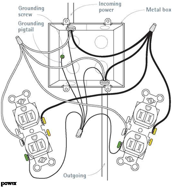
Подпись: Wiring a Fourplex Receptacle in a Metal BoxПодпись:Подпись: A two-gang box with fourplex (double duplex) receptacles will be crowded. Especially if the box is metal, use insulated ground pigtails, wrap electrical tape around receptacle bodies to prevent screw terminals from shorting out, and always ground the box (see the bottom photo on p. 243).Подпись: Wiring a GFCI ReceptacleПодпись: From power sourceПодпись: Spliced ground wiresПодпись:image502

A GFCI receptacle in midcircuit can protect receptacles downstream, if correctly wired. Attach wires from the power source to terminals marked “LINE." Attach wires continuing to receptacles downstream to terminals marked “LOAD." As with any receptacle, attach hot wires to gold screws, neutral wires to silver screws, and grounding wires to the green ground screw. Note: Here, only ground wires are spliced; hot and neutral wires attach directly to screw terminals.

Ganging. By ganging devices you can make the most of limited wall or counter space. Most often, a switch and a receptacle are housed in a single four-square box (4 in. by 4 in.) or in two smaller metal boxes ganged together. Two recep­tacles will also fit. When in doubt, consult the table "Box Fill Worksheet,” on p. 240, to make sure that the box in question is big enough. When ganging two devices, use two pigtails per wire group so you ensure continuity downstream.

DRILLING HOLES

With the boxes in place, drill holes to run cable from the service panel to the outlet boxes. As noted earlier, a h-in. right-angle drill with a 7/-in. Nail Eater wood-boring bit is the tool of choice.

For individual circuits, in which a cable serves only one appliance, reduce the amount of hole drilling by drilling up through the top plate(s) above the appliance and running cable through the attic till you’re above the service panel. Then drill holes down through the wall plates so you can drop the cable to the panel.

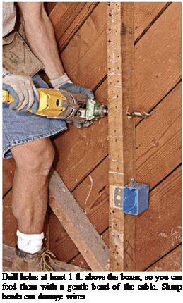
For circuits with many wall outlets, drill through studs 12 in. above the outlet boxes, so the cable can bend gradually toward the boxes. (Avoid sharp bends, which can damage wire insu­lation.) All holes should be centered in the studs, so that the cable is at least 1’/ in. away from the stud edges; that way drywall screws can’t punc-

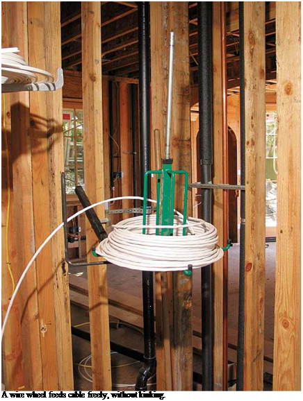
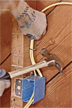
Подпись: A wire wheel feeds cable freely, without kinking. Подпись: Staple cable within 8 in. of singlegang plastic boxes and within 12 in. for all others. Cables should lie flat beneath the staple; never staple cable on-edge.Подпись: PROTIP The NEC requires at least 6 in. of "free" wire in a box, and at least 3 in. of it can extend beyond the front of the box. But seasoned electricians usually leave more wire sticking out. For inspectors, short stubby wires are the mark of an amateur. 1111 image490

ture it. If a cable is closer than 114 in., nail steel nail-protection plates to the studs. Be careful to drill holes at the same height. It’s much easier to pull cable through lined-up holes. A right-angle drill will also ensure that the holes are perpendi­cular to studs.

Sometimes it’s easier to run cable around an obstruction. For example, it’s possible to run cable through the corner studs if the holes are at the same height and there’s no 2 X blocking at the point where you drill. But if you’re running 12/2 cable or heavier, the cable will be too stiff to pull through the holes at right angles. In this case, drill through the wall plates and go over or under the corner. Likewise, drilling through dou­bled studs on either side of a door or window opening is a lot of work. So go around.

Finally, drill holes for cable "home runs”— lengths of cable that run from the panel board to the outlet box on each circuit that is closest to the panel.

PULLING CABLE

Pulling Romex cable is easier if you reel it off a wire wheel, a rotating cable dispenser that nails to framing and holds 250-ft. coils. Start by plac­ing the wire wheel near each home-run box and pulling off enough cable to extend roughly 1 ft. beyond each box and 4 ft. beyond the knockout where each cable enters the panel. When in doubt, run cable long. For example, wires inside a service panel may need to run 3 ft. to 4 ft. to reach a neutral or ground bus on the opposite side of the panel.

To run cable for individual circuits, again place the wire wheel near each home-run box, but this time pull cable "downstream”—away from the service panel. Many electricians pull cable through holes to the far end of the circuit and then walk back, pulling out additional cable loops that reach at least 8 in. beyond each box. After running cable to all outlet boxes, cut each loop and feed the cable ends into the box open­ings or knockouts, so the cables stick out about 8 in. Although most duplex receptacle boxes will contain two cables, double – or triple-gang boxes may have four or more.

Staple cable within 12 in. of most boxes, and every 4h ft. thereafter. However, if you’re using single-gang plastic boxes without internal cable clamps, staple cable within 8 in. of the boxes. Don’t overdrive the staples; cable should be just snug. When cable runs parallel to joists, staple it to the sides of the joists. When cable runs per­pendicular to joists, drill holes through the joists or staple the cable to the underside of each joist. Alternatively, you can nail a 1 X 4 board to the underside of the joists and then staple cable to it.

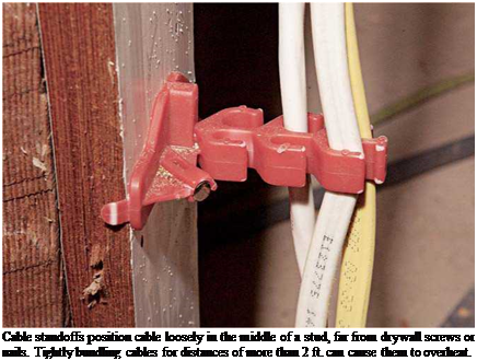
Подпись: Identifying Cable Runs To avoid confusion when it's time to wire devices, identify incoming cables. Use felt-tip markers to write on the cable sheathing or write on masking tape wrapped on grouped wires. Cables running from the panel board to an outlet should be marked "SOURCE," "FROM SOURCE," or "UPSTREAM." If you're wiring GFCI receptacles, these incoming cable wires attach to GFCI terminals marked "LINE." Cables running on to the next outlet (away from the power source) are denoted "NEXT OUTLET" or "DOWNSTREAM"; they attach to GFCI terminals marked "LOAD." Double- or triple-gang boxes will have a lot of cables entering, so make the cable descriptions specific: "SWITCH LEG TO CEILING FIXTURE," "THREE-WAY SWITCH #2," and so on. Подпись: Cable standoffs position cable loosely in the middle of a stud, far from drywall screws or nails. Tightly bundling cables for distances of more than 2 ft. can cause them to overheat. Подпись: TIP CABLE CONNECTORS (CLAMPS)Подпись:

Подпись: Use a screwdriver or lineman's pliers to remove the metal box knockouts. Cables entering through such openings must be protected by cable connectors.
image492

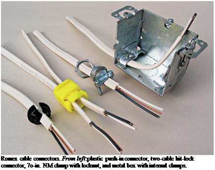
All outlet boxes must have clamps that grip cables, except single-gang plastic boxes whose cables must be stapled within 8 in. of the box. (Several Romex connectors are shown in the photo on p. 243.) Clamps secure cable so its con­nections can’t be yanked—thus preventing strain on connections inside the box. Plastic boxes have tension clamps that allow cable to be pulled in, but not out. When you’re fishing wire and installing cut-in boxes, cable clamps are crucially important because it’s impossible to staple cable hidden by walls.

Cable clamps in metal boxes also keep wires from being nicked by burrs created when metal box knockouts are removed. (Use a screwdriver to start knockouts and lineman’s pliers to twist

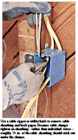
them free.) To further protect wire insulation, leave a small amount of cable sheathing—roughly h in.—sticking out from under clamps. That is, clamps should tighten down on a remnant of sheathing, not on individual, unsheathed wires. Finally, don’t overtighten clamps, which could damage the wire insulation. And if you remove a knockout mistakenly, use a knockout plug to cover the hole; a knockout plug is a thin cap with barbed sides or spring clips that expand after they clear the edge of the knockout hole. Use one cable per clamp unless the manufacturer allows more.

STRIPPING SHEATHING

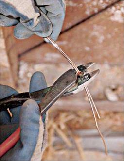
Many electricians use a utility knife to slit and remove plastic sheathing, lightly running the blade tip down the middle of the cable, over the bare ground wire inside. To remove sheathing with less risk of nicking wire insulation, use a cable ripper to slit the sheathing or a cable strip­per to remove a sleeve of sheathing. Use a utility knife or side-cut pliers to cut free any slit sheath­ing or kraft paper still in the box. Tighten the cable clamps; then group like conductors—hot wires to one side, neutrals to the other, grounds in the middle—and cut all wires to the same length, roughly 8 in.

Подпись:

Подпись: Crimping ground wires is quicker than splicing them with wire nuts. After crimping the sleeve, leave one ground wire long. Then attach it to the green ground screw of a receptacle.
image494

Splicing ground wires. To ensure a continuous ground throughout the system, splice together copper ground wires, using wire nuts or crimps. Ground wires are usually bare copper; if they’re green insulated wires, first strip approximately % in. of insulation off their ends.

To use wire nuts, first cut the ground wires to the same length, and butt their ends together, along with a 6-in. pigtail that you’ll later connect to the green ground screw of a receptacle. (The grounding pigtail can be bare copper or insulated wire whose ends have been stripped.) Use line­man’s pliers to twist the stripped wire ends clock­wise. Trim the ends of the grouped ground wires even; then twist on a wire nut, turning it in a clockwise direction. The threads inside the wire nuts cut into and bind the bare wires. Give a gen­tle tug to be sure the splice is complete.

To crimp ground wires, gather the wires but don’t twist them. Feed them through a copper sleeve, use a crimping tool to crimp the sleeve tight before snipping all the wires—except one— even with the sleeve. This one long ground wire emerging from the crimped group will connect to the green ground screw of a receptacle. You can use wire nuts to splice (join) ground wires; but crimping them is faster.

If the box is metal, it too must be grounded. Many electricians simply loop the bare-wire grounding pigtail and screw the loop to a green screw in the metal box. The bare-wire pigtail then continues on, to connect to the grounding screw on the receptacle. Or you can add a second pigtail to the ground-wire splice, so that the first screws to the metal box and the second to the receptacle, but that eats up space in the box and slows down the work.

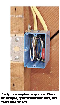
At this point, most local codes require a rough-in inspection. In addition to outlet boxes, inspectors will examine any connections in junc­tion boxes, typically 4-sq.-in. boxes. All electrical connections must be housed in covered boxes, but you must leave junction box covers off till the rough-in inspection is done.

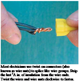
Splicing neutral and hot wires in outlet boxes is essen­tially the same as splicing ground wires. Once again, a pig­tail runs from both the hot and the neutral wire groups and attaches to the appropriate screw terminal on the recepta­cle. Because neutral and hot wires are always insulated, use wire strippers to strip the insula­tion off the wire ends.

Подпись: Most electricians use twist-on connectors (also known as wire nuts) to splice like wire groups. Strip the last 3A in. of insulation from the wire ends. Twist the wires and wire nuts clockwise to fasten. Feed the wire into an appro­priately sized hole in the tool’s jaws, squeeze the handles, and rock the tool so it cuts the insu­lation but doesn’t score the con­ductor. If you are using wire

Подпись: Ready for a rough-in inspection: Wires are grouped, spliced with wire nuts, and folded into the box. image497nuts to splice wire groups, strip roughly M in. of insulation from the wire ends; then twist each wire group together, using lineman’s pliers. If you are attaching a pigtail to the receptacle or fixture screws, strip h in. of insulation. Back-wired switches and receptacles have stripping gauges on the back that show how much to strip.
At switches, do not splice hot wires; splice only neutral and ground wire groups. Switches turn fixtures off and on by interrupting the cur­rent flowing through hot wires. Therefore, you must attach hot wires to switch terminals, not to each other.

LOCATING AND MOUNTING BOXES

After mapping the wiring plan, you can install the boxes. But if you’re wiring someone else’s house, first do a walk-through with the owners so they can approve the locations. Use a builder’s crayon or a heavy marker to indicate boxes or temporarily tack-nail (or screw-fasten) the boxes in place.

Box heights. There are few set rules about locat­ing boxes. Set the bottom of outlet boxes 12 in. above the subfloor, or use a hammer to approxi­mate box height, as shown in the top left photo on p. 244. In housing for disabled occupants, out­let box bottoms should be a minimum of 15 in. above the subfloor. For outlets over kitchen and bath counters, set the box bottoms 42 in. from the subfloor, so they’ll end up 8 in. above the counters and 4 in. above a standard 4-in.-high backsplash.

Locate wall switches on the lock side of a door (the side opposite the hinges). If you set the bot­toms of the switch boxes 44 in. or 48 in. above the subfloor, the box bottoms will align with the seam of a 48-in.-wide drywall panel installed horizontally—which means you’ll need to cut out only one panel. However, if a carpenter has added blocking at that height to nail the panel edges, raise the boxes till they clear the blocking.

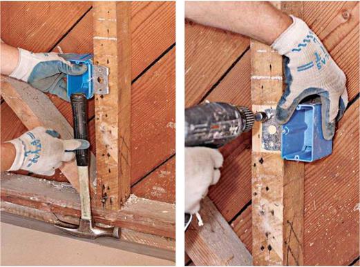
Mounting boxes. Mount boxes so they’ll be flush with finish surfaces. Most boxes have tabs or gauge marks stamped on the side to indicate dif­ferent surface thicknesses. If that’s not the case, hold a scrap of the finish material—for example, %-in. drywall—next to the front edge of the box as a depth gauge. Unless you’re installing nail-in boxes, use screws to mount the boxes so you can make adjustments if you need to. The depth of the Veco box shown on p. 244 can be adjusted after the drywall is up.

To attach ceiling boxes, you have these three choices: (1) screw the box directly to a joist;

(2) end-nail a piece of blocking between the

Use a hammer to set the box heights. This is much quicker than measuring, yet almost as accurate. Boxes will be roughly 12 in. above subfloors; set them 15 in. above the floor for disabled persons, if required.


Adjustable boxes can be raised or lowered till they’re flush with the finish walls. Here, the adjustment screw is visible below the electrician’s thumb. Note the bare wood under the mounting bracket: One pass of a power plane sets the brackets flush to the stud edges.


image487

Подпись: Drill holes at least 1 ft. above the boxes, so you can feed them with a gentle bend of the cable. Sharp bends can damage wires. joists, and screw the box to that; or (3) install an adjustable metal hanger bar between the joists, to which the box is mounted. Ceiling boxes must be secured to the structure, not merely to the fin­ish ceiling, so that the fixture will be adequately supported.
FIXTURES, AND SWITCHES

Although all UL-rated fixtures, switches, and receptacles will satisfy electrical codes, better – quality devices will last longer. Heavy-duty recep­tacles, for example, have nylon faces rather than plastic and metal support yokes that reinforce the back of the receptacle.

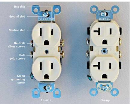
Receptacles. Most household receptacles are rated for 15-amp circuits and wired with 14AWG or 12AWG wire. The NEC specifies 20-amp protection for kitchen appliance, garage, and workshop circuits.


The NEC specifies GFCI protection for many locations, including bathroom, outdoor, and kitchen counter receptacles, so there are also 15-amp and 20-amp GFCI receptacles. In addi­tion, you can obtain various kinds of specialty 15-amp receptacles, including childproof models that require an adult’s grip to uncover them, weatherproof receptacles that combine cover and receptacle in an integral unit, recessed receptacles in which clock wires can be hidden, covered floor receptacles, and many more. In addition, there are receptacles specifically matched to the plugs of 30-, 40-, or 50-amp appliances. Your electrical supplier can tell you what’s available.


PROTIP

When cleaning touch-pad dimmers, wipe with only a clean soft rag, a damp sponge, or a cleaner recommended by the manufacturer. Touch pads are so sensitive that the wrong spray – on cleaner can make them go haywire, causing lights to cycle wildly up and down!

1111


Fixtures. Lighting fixtures vary greatly, from elaborate multibulb configurations to simple pull-chain porcelain fixtures. Most attach to a ceiling outlet box with two machine screws. Branch-circuit wires attach directly to two screws on the fixture (white wire to silver screw, black to gold screw) or, more commonly, to two color – coded lead wires from the fixture. Metal fixture boxes must be grounded.

Switches. Switches come in a variety of configu­rations. They include single pole, which control lights from a single location; three-way, which control lights from two locations; four-way, which control lights from three locations; rheostats (dimmer switches), which dim and brighten lights gradually; touch-pad dimmers, which respond to finger pressure rather than a mechanical switch; pilot-light combos, whose small bulbs shine when an attic or basement light is still on; switch-receptacle combos; pro­grammable switches; and space-saver switches.

Before installing any of the more exotic switches, make sure switch amperage matches that of the load (electrical demand of an appli­ance or piece of equipment) you’re feeding. And never run appliances or tools on a rheostat- controlled outlet. Rheostats vary voltage, and without full voltage, appliance or tool motors can burn out.

Rough-In Wiring

As noted earlier, electricians distinguish between new work and old work (remodel) jobs, regardless of the age of the building or the extent of the upgrade. New work means that framing is exposed, so you can attach boxes to studs or ceil­ing joists and easily drill holes for cable; whereas remodel wiring usually entails mounting cut-in boxes to finish surfaces and fishing cable through walls or floors to add outlets to existing circuits.

Certainly, the two approaches have a lot in common. But to avoid repetition, the following


ЙІ і


LEVITON I


21


The 20-amp receptacle (at right) has a horizontal slot so it can receive a special 20-amp plug in addition to standard 15-amp plugs. Unlike 20-amp receptacles, 15-amp receptacles cannot receive 20-amp plugs. Thus 20-amp receptacles cannot be used on 15-amp circuits.

image484

FIXTURES AND RECEPTACLES


Fixtures and receptacles are polarized, so they fit together only one way. On a correct­ly wired light fixture, the neutral wire of the lamp cord connects to the silver screw shell (where the bulb screws in); whereas the hot wire connects to a brass tab inside the bottom of the screw shell. Should you inadvertently touch the side of the screw shell, there’s no harm done. Whereas, if you reverse the order in which wires are attached-known as reversing the polarity—the outside of the screw shell becomes hot (energized) and could shock someone changing a bulb.

Receptacles and plugs are also polarized. A receptacle’s gold screw terminal connects to hot wires and, internally, to the hot (narrow) prong of a polarized plug. The receptacle’s silver screw terminal connects to neutral wires and, internally, to the neutral (wide) prong of a polarized plug. Finally, the green ground screw connects to the ground wire and the U-shaped grounding prong of the plug.


image485

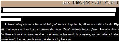
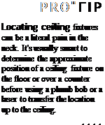
Подпись: When installing receptacles in a metal box, wrap electrical tape around the sides of the receptacle to cover and insulate the screw terminals.image486Подпись: lest BEFORE YOU TOUCH ? Before handling electrical wires or devices—or before cutting into finish surfaces around them—disconnect the power to that area and test with a voltage tester to make sure that the power is off. Before doing any work in the vicinity of an existing circuit, disconnect the circuit. Flip off the governing breaker or remove the fuse. (Don't merely loosen fuses. Remove them.) And leave a note on your service panel announcing work in progress, so that others in the house won't inadvertently turn the electricity back on. Подпись: PRO"ГIP Locating ceiling fixtures can be a literal pain in the neck. It's usually smart to determine the approximate position of a ceiling fixture on the floor or over a counter before using a plumb bob or a laser to transfer the location up to the ceiling. 1111

sections discuss their common elements in the context of new work and then examine the specif­ics of remodel wiring. Assume that nonmetallic cable (Romex) is being installed. Brief sections on installing MC cable and conduit will follow.

OVERVIEW

Electricians further divide installations into rough-in and finish phases. After the rough-in, there’s always an inspection by an authority hav­ing jurisdiction (AHJ). The following sequences are greatly oversimplified.

Rough-in phase.

1. Locate and mount boxes.

2 Drill holes, and run cable.

3. Feed cables into boxes, staple cables to studs, and clamp cables to boxes.

4. Remove the sheathing of cables inside boxes, group like wires and cut them to equal length, join ground wires, and fold all wires into the boxes.

Finish phase. The finish, or trim, phase takes place after a rough inspection has been signed off by the AHJ and the finish surfaces have been installed and painted.

1. Strip insulated wire ends, and then splice them together—black to black, white to white. Leave switch hot wires unspliced.

2. Attach wires to receptacles, fixtures, and switches.

3. Push wired devices into the boxes, and screw the devices to the boxes.

4. Screw on the cover plates.

CIRCUIT WIRING

Copper is the preferred conductor for residential circuit wiring. Aluminum cable is frequently used at service entrances, but it is not recommended in branch circuits.

Individual wires within a cable or conduit are color coded. White or light gray wires are neutral conductors. Black or red wires denote hot, or load­carrying, conductors. Green or bare (uninsulated) wires are ground wires, which must be connected continuously throughout an electrical system.

Because most of the wiring in a residence is 120-volt service, most cables will have three wires: two insulated wires (one black and one white) plus a ground wire, usually uninsulated. Other colors are employed when a hookup calls for more than two wires; for example, 240-volt circuits and three – or four-way switches.

BOXES

There is a huge selection of boxes, varying by size, shape, mounting device, and composition. But of all the variables to consider when choosing boxes, size (capacity) usually trumps the others. Install slightly oversize boxes, if possible: They’re faster to wire and, all in all, safer because jamming wires into small boxes stresses connections.

image479

WIRING

Aluminum wiring was widely used in house circuits in the 1960s and 1970s, but it was a poor choice. Over time, such wiring expands and contracts excessively, which leads to loose connections, arcing, overheating and—in many cases—house fires. If your house has aluminum circuit wiring, the most common symptoms will be receptacle or switch cover plates that are warm to the touch, flickering lights, and an odd smell around electrical outlets. Once arcing begins, wire insulation deteriorates quickly.

An electrician who checks the wiring may recommend adding COPALUM® connectors, CO/ALR-rated outlets and switches, or replacing the whole system.

Note: Aluminum service cable, thick stranded cable that connects to service panels, is still widely used because it attaches solidly to main lugs, without problems.

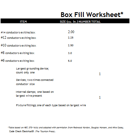
Capacity. The most common shape is a single­gang box. A single-gang box 3f2-in. deep has roughly 22Й cu. in. capacity: enough space for a single device (receptacle or switch), three 12/2 W/G cables, and two wire nuts. Double-gang boxes hold two devices; triple-gang boxes hold three devices. Remember: Everything that takes up space in a box must be accounted for— devices, cable wires, wire nuts, and cable clamps— so follow closely NEC recommendations for the maximum number of conductors per box.

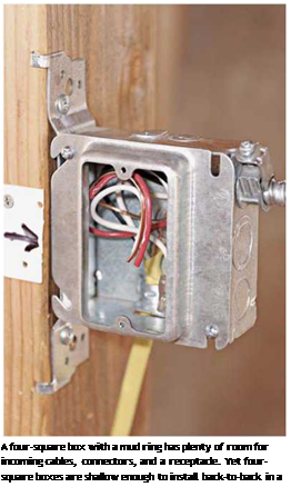
You can get the capacity you need in a num­ber of ways. Some pros install shallow four­squares (4 in. by 4 in. by 1И in. deep) throughout a system because such boxes are versatile and roomy. If a location requires a single device, pros just add a mud ring cover, as shown in the photo on p. 240. Because of their shallow depth, these boxes can also be installed back to back within a standard 2×4 wall. Thus you can keep even back-

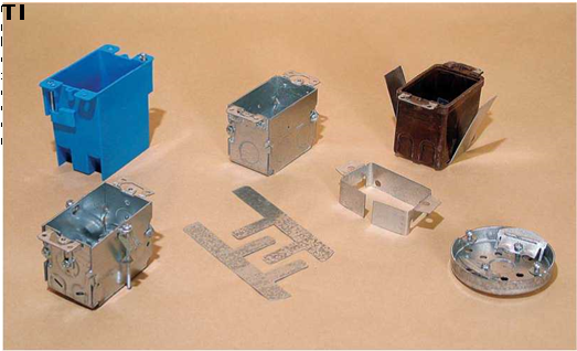
Подпись: VERSUS PLASTIC BOXES Подпись: Metal boxes are sturdy and are available in more sizes than plastic boxes. Some metal boxes can be interlocked for larger capacity. Also, metal boxes are usually favored for mounting ceiling fixtures because steel is stronger than plastic. If code requires steel conduit, armored cable (BX), or MC cable, you must use steel boxes. All metal boxes must be grounded. For most other installations, plastic is king. (Plastic boxes may be PVC, fiberglass, or thermoset.) Electricians use far more plastic boxes because they are less expensive. And, because they are nonconductive, they don't need to be grounded and are quicker to install. However, even if a box doesn't need to be grounded, all electrical devices within must be grounded by a continuous ground. Another reason to buy plastic: Box volumes are stamped on the outside. to-back switch boxes at the same height, from room to room. Shallow pancake boxes (4 in. in diameter by J2 in. deep) are commonly used to flush mount light fixtures.
Mounting devices. The type of mounting bracket, bar, or tab you use depends on whether you’re mounting to finish surfaces or structural mem­bers. When you’re attaching a box to an exposed stud or joist, you’re engaged in new construction or new work, even if the house is old. New-work
boxes are usually side-nailed or face-nailed through a bracket; nail-on boxes have integral nail holders. The mounting bracket for Veco® nonmetallic boxes is particularly ingenious (see the photos on p. 244). Once attached to framing, the box depth can be screw adjusted till it’s flush to the finish surface.

Adjustable bar hangers enable you to mount boxes between joists and studs; typically, hangers adjust from 14 in. to 22 in. Boxes mount to hangers via threaded posts or, more simply, by being screwed to the hangers. Bar hangers vary, too, with heavier strap types favored in walls, where boxes can get bumped more easily. Lighter hangers, as shown on p. 239, are typically used in ceilings, say, to support recessed lighting cans.

Подпись: Box Fill Worksheet* ITEM SIZE (cu. in.) NUMBER TOTAL #14 conductors exiting box 2.00 #12 conductors exiting box 2.25 #10 conductors exiting box 2.50 #8 conductors exiting box 3.0 #6 conductors exiting box 5.0 Largest grounding device; count only one 1 Devices; two times connected conductor size Internal clamps; one based on largest wire present 1 Fixture fittings; one of each type based on largest wire Total *Table based on NEC 370-16(b) and adapted with permission from Redwood Kardon, Douglas Hansen, and Mike Casey, Code Check Electrical® (The Taunton Press). Подпись: A four-square box with a mud ring has plenty of room for incoming cables, connectors, and a receptacle. Yet four-square boxes are shallow enough to install back-to-back in a 2x4 wall.

Cut-in boxes. The renovator’s mainstay is cut-in boxes because they mount directly to finish sur­faces. These boxes are indispensable when you want to add a device but don’t want to destroy a large section of a ceiling or wall to attach to the framing. Several types are shown in the top photo at right. Most cut-in boxes have plaster ears that keep them from falling into the wall cavity; what vary are the tabs or mechanisms that hold them snug to the back side of the wall: screw – adjustable ears, metal-spring ears, swivel ears, or

Подпись: Romex cable connectors. From left:plastic push-in connector, two-cable hit-lock connector, 7o-in. NM clamp with locknut, and metal box with internal clamps.

image483

bendable metal tabs (Grip – loks™). Important: All cut-in boxes, whether plastic or metal, must contain cable clamps inside that fasten cables secure­ly. That is, it’s impossible to sta­ple cable to studs and joists when they are covered by finish surfaces, so you need clamps to keep the cables from getting tugged or chafed by metal box’s edge.

Clamps. Every wiring system— whether nonmetallic (Romex), MC, or conduit—has clamps (connectors) specific to that sys­tem. Clamps solidly connect the cable or conduit to the box so there can be no strain on elec­trical connections within the box and, as important, Romex clamps protect cable sheathing from burrs created when a metal box’s knockouts are removed.

CIRCUIT WIRING

Подпись:GETTING BOX Edges FLUSH

Use an Add-a-Depth ring ("goof ring") to make box edges flush when an outlet box is more than ‘A in. below the surface—a common situation when remodelers dry – wall over an existing wall that’s in bad shape. To prevent the metal goof ring from short-circuiting screw terminals, first wrap electrical tape twice around the body of the receptacle or switch.

Reading a Cable

Cables provide a lot of information in the abbreviations stamped into their sheathing; for example, NM indicates nonmetallic sheathing, and UF (underground feeder) can be buried. The size and number of individual conductors inside a cable are also noted: 12/2 w/grd or 12-2 W/G, for example, indicates two insulated 12AWG wires plus a ground wire. Cable stamped 14/3 W/G has three 14AWG wires plus a ground wire. (The higher the number, the smaller the wire diameter.) The maximum voltage, as in 600V, may also be indicated.

Individual wires within cable have codes, too. T (thermoplastic) wire is intended for dry, indoor use, and W means "wet"; thus TW wire can be used in dry and wet locations. H stands for heat-resistant. N, for nylon jacketed, indi­cates a tough wire than can be drawn through conduit without being damaged.

Finally, make sure the cable is marked NM-B. Cable without the final "-B" has an old-style insu­lation that is not as heat resistant as NM-B cable.

CABLE, CONDUIT, AND WIRING

Most house wiring is flexible cable, but you may find any—or all—of the wiring types described here. Inside cables or conduits are individual wires, or conductors, that vary in thickness according to the amperage of the current.

► Nonmetallic sheathed cable (NM or Romex) is by far the most common flexible cable. Covered with a flexible thermoplastic sheathing, Romex is easy to route, cut, and attach.

► Metal-clad cable (MC) is often specified where wiring is exposed. Note: Some codes still allow armored cable (AC), but that’s increasingly rare.

► Conduit may be specified to protect exposed wiring; it is commonly thin-wall steel (EMT), aluminum, or PVC plastic. Metal conduit serves as its own ground. Apart from service entrances, conduit is seldom used in home wiring. When connected with weather – tight fittings and boxes, conduit can be installed outdoors.

► Knob-and-tube wiring (see the top photo on p. 15) is no longer installed, but there’s still plenty of it in older houses. If its sheathing is

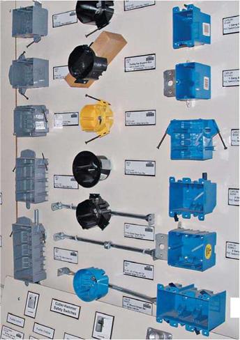
Подпись: There are hundreds of options for outlet boxes. The sample of blue plastic boxes at right shows [from top) one-gang cut-in, one-gang adjustable, two-gang nail-on, two-gang cut-in, two-gang adjustable, and three-gang boxes. The multicolored boxes in the middle are ceiling boxes. Подпись: Г~Iimage478

intact and not cracked, it may still be serviceable. You may even be able to extend it, but have an electrician do the work. Knob-and – tube is eccen­tric, requiring experience and a skilled hand.

TIP

In some very old houses, you may find that the neutral wires were attached to a switch— rather than the hot wires, as required by codes today. Thus, when working on old switches or fixtures, test all wires for current. Even if you’ve flipped a fixture switch off, there could still be a hot conductor in the fixture outlet box.

llll

image476
Подпись: TIP
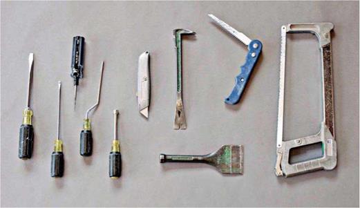
Подпись: Miscellaneous tools. From left:two slot-head screwdrivers, tapper (to cut threads in metal box holes), offset screwdriver, nut driver, utility knife, small pry bar/nail puller, plaster chisel, drywall saw, and hacksaw.

Подпись:

when an outlet is too distant. Cordless tools now have all the power you could want. Besides, they don’t need an extension cord and won’t electrocute you if you inadvertently drill or cut into a live wire. Cordless reciprocating saws can cut anything from plaster lath to studs; but use

a cordless jigsaw if you want to preserve the plaster around a cut-in box opening.

Miscellaneous tools. Other necessary tools include a hammer, tape measure, Speed Square, hacksaw, plaster chisel, drywall saw, nut driver, small pry bar, and spirit level.

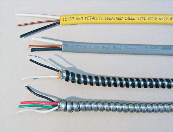
Electrical cable. From top:type NM (Romex), type UF (underground), armor clad (AC), and metal clad (MC). Note: The silver wire in the AC cable is a bonding wire, not a ground. In the MC cable, the green wire is ground, the white is neutral, and the red and black are hot.


image477

Choosing an Electrical Tester

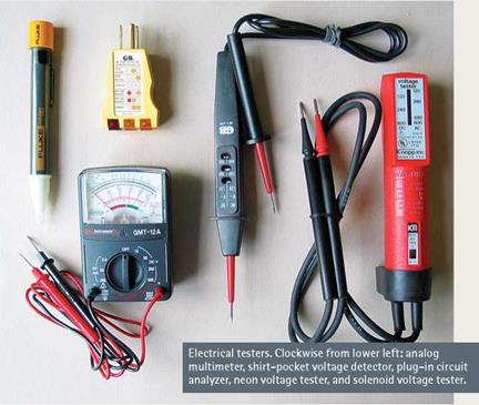
Testing to see if an outlet is energized is so critical to professional electricians that there are scores of specialized testers to choose from, some of which cost hundreds of dollars. Fortunately, amateur electricians can get a reliable tester for less than $30. Here are five types:

► Neon voltage testers are inexpensive and versatile. Insert the probes (prongs) into the receptacle slots or touch them to the screw terminals or to a metal outlet box to see if the unit is hot (energized). Buy quality: Better neon testers have insulated handles, whereas cheapies have bare metal probes so short that you risk shocking yourself when using them.

► Plug-in circuit analyzers can be used only with three-hole receptacles, but they quickly tell you if a circuit is correctly grounded and, if not, what the problem is. Different light combinations on the tester indicate various wiring prob­lems, such as no ground, hot and neutral reversed, and so on. Quite handy for quick home inspections.

► Shirt-pocket voltage detectors give a reading without directly touching a conductor. Touch the tool’s tip to an outlet, a fixture screw, or an electrical cord, and the tip glows red if there’s voltage present. Because they depend on battery power, voltage detectors are somewhat less reliable than other options, but all in all, it’s an ingenious tool.

► Solenoid voltage testers (often called "Wiggy’s") test polarity, AC, and DC voltage from 100 volts to 600 volts. Most models vibrate and light a bulb when current is present. Solenoid testers don’t use batteries, so readings can’t be compro­mised by low battery power. However, because of their low impedance, solenoid testers will trip GFCIs.

► Multimeters, as the name suggests, offer precise readings in multiple scales, which you select beforehand, although some models are autoranging (they select the correct scale). Extremely sensitive, they can detect minuscule amounts of current. Better models test AC and DC voltage, resistance, capacitance, and frequency.

image474

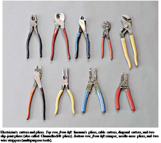
Подпись: Electrician's cutters and pliers. Top row, from left: lineman's pliers, cable cutters, diagonal cutters, and two slip-joint pliers (also called Channellock® pliers). Bottom row, from left:crimper, needle-nose pliers, and two wire strippers (multipurpose tools).