Category Timber Framing for the Rest of Us Rob Roy

Deflection

Deflection is similar to bending… but different. Bending concerns us most when it translates into bending failure, which is a bad thing. With deflection, we can tolerate certain amounts of it in certain circumstances. Springiness — or stiffness — in a floor is a characteristic of deflection. Cracking plaster on a ceiling, or separation of taped sheetrock joints, is an indication of excessive deflection.

Deflection is commonly expressed as a percentage or fraction of the span. Two common fractions you will encounter in span tables are V240 and V360 of a span. If a floor sags one inch over 240 inches (20 feet or 6 meters), this is a deflection of V240. A half-inch sag in 180 inches (15 feet or 4.6 meters) is an example of a deflection of V360. Charles Wing, author of several good books on homebuilding and sometimes called the father of the modern owner-builder movement, likes the V360 rule for first floors, where, normally, you don’t want to experience too much springiness.

There are also “rules” for ceilings. If you are supporting a plaster ceiling, deflection should be no greater than V360. With gypsum board, taping, and spackling, you can get by with V240 deflection. For roof rafters, a deflection of V180 is normally allowable by code.

Personally, I don’t use plaster or plasterboard ceilings, and I seldom use any kind of span greater than ten feet, because I put heavy earth roofs on almost every building I’m involved with. So, deflection has never been a big issue. With exposed plank ceilings, V180 of deflection would be fine for roof rafters, and V240 would certainly be acceptable for any floor with a wood ceiling beneath it.

Normally, if a floor joist or roof rafter plan meets the criteria for allowable loads on bending, it will be fine on deflection. Simply use commonly available span tables. I have included examples of some basic span tables in Appendix A, and also a list of where more comprehensive tables can be found. Here is just one example, to give you an idea of the kinds of dimensions we’re talking about, and I get this right out of the new International Residential Code for One – and Two – Family Dwellings, Table R502.3.1(2), a portion of which is reproduced in Appendix A. We assume that this is a residential living area with a live load of 40 pounds per square foot (PSF), a dead load (structural load) of 10 PSF and an allowable deflection of V360. Using Douglas Fir-Larch #1, and with joists 16 inches on center, a two-by-eight can span 13 feet 1 inch (3.99 meters). With two – by-tens, the allowable span increases to 16 feet 5 inches (5.0 meters). With a lesser quality of wood, such as #2 Southern Pine, the allowable spans drop to 12 feet 3 inches (3.12 meters) for two-by-eights and 15 feet 5 inches (4.7 meters) for two-by – tens. For residential sleeping areas, where loads of 30 pounds per square foot is assumed, allowable spans are greater. Find these figures in Appendix A, Table 1, and you will be well on your way to being able to use span tables.

Also in Appendix A, there are two examples of using a rafter span table with a 70-pound snow load and a 20- pound dead load. Back to posts…
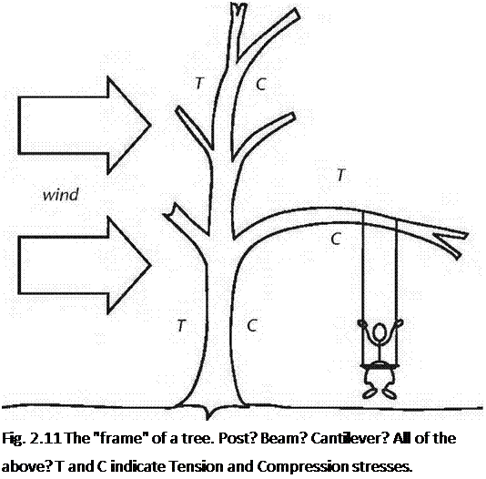
Подпись:We do not normally think of vertical members, such as posts or even trees, as being beams, but, in fact, they share a lot in common with beams.

The word “beam” even comes from an old English word meaning tree or tree trunk. When a tree is being blown by the wind, the windward side is in tension as the tree bends away from the wind. The leeward side is in compression. Actually, as the tree is unsupported at the top, it can be thought of as a cantilever, just another kind of beam. A tree branch, extending out from the trunk, is a cantilever built out from a cantilever. We’ll speak more of cantilevers in a moment.

In “post and beam” construction, the posts are the naturally strong component, because they are extremely strong on compression. For example, a six-by-six of a relatively low compressive strength of 1,150 to 1,400 inch-pounds per square inch (you don’t really have to know what this unit means to get the point here; I certainly don’t) will support 32,800 pounds at eight feet of height. That’s 16.4 tons! An eight-by-eight of the same quality will support 63,000 pounds, 31.5 tons.

Tons, I understand. Even with our two stories and heavy earth roof, five of the seven major eight-by-eight posts at Earthwood support about 10,000 pounds each and the other two (full-sized eight-by-eight solid oak) support only 15,000 each, way under their capacity. (An oak eight-by-eight is good for over 93,000 pounds at eight feet of height.) In short, the post part of “post and beam” framing is very strong.

Four-by-fours would actually do for five of the seven posts at Earthwood if it weren’t for our esthetic sensibilities and something called “slenderness ratio” or SR. Visually, a four-by-four supporting an eight-by-eight or ten-by-ten girder just doesn’t look right, like a four-by-eight rafter laid the wrong edge down. But, structurally, the four-by-four post would probably do the job.

“Slenderness ratio” is simply the relationship of the width of the post its length. A 96-inch (8-foot or 2.44-meter high) post that is only four inches wide on its narrowest dimension has an SR of 96 inches/ 4 inches, or 24. Put an eight-by-eight there, and the SR becomes 96 inches/ 8 inches, or 12. The higher the number, the weaker the post. A slender post is much more subject to buckling than compression failure. Lets say we had a four-by-four supporting a heavy load as a post, and that there was a large knot on one or more edges of the post. While knots can be fairly strong in compression, they are weak in tension, as they tend to separate easily from the surrounding wood. A lateral load, such as a sudden impact, or the oscillation during an earthquake, could easily cause such a post to buckle and fail. Extreme vertical loads could do it, as well.

Shear and Shear Failure

Shear failure is much more difficult to envision than bending failure. In fact, with light frame construction, shear failure seldom comes into play, whereas it is an important consideration for heavy timber framing, particularly with a very heavy load such as an earth roof or a steam train.

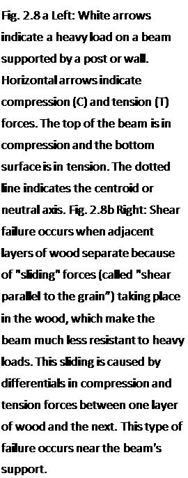
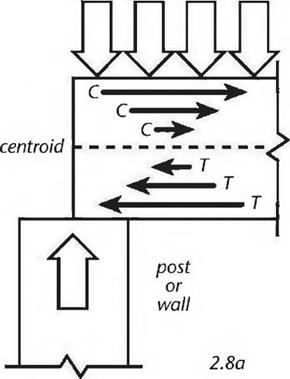
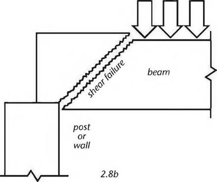
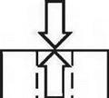
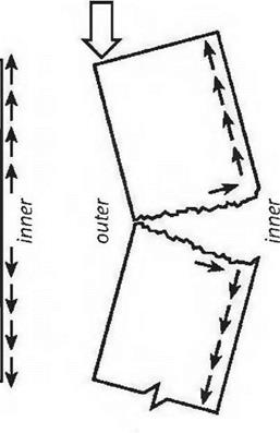
Подпись: Fig. 2.8 a Left: White arrows indicate a heavy load on a beam supported by a post or wall. Horizontal arrows indicate compression (C) and tension (T) forces. The top of the beam is in compression and the bottom surface is in tension. The dotted line indicates the centroid or neutral axis. Fig. 2.8b Right: Shear failure occurs when adjacent layers of wood separate because of "sliding" forces (called "shear parallel to the grain”) taking place in the wood, which make the beam much less resistant to heavy loads. This sliding is caused by differentials in compression and tension forces between one layer of wood and the next. This type of failure occurs near the beam's support.One good way of explaining shear is to think of it as a combination of compression and tension stresses. Remember that the top surface of a beam is in compression, the bottom surface is in tension, and the centroid (middle part of the beam) is neutral (thus also called the neutral axis.) Fig. 2.8a shows the compression and tension forces at one end of a beam, where it is supported over a post or wall. The arrows show the compression and tension forces. Note that the arrows are pointing in opposite directions, and that the strength of the compression or tension forces diminishes closer to the neutral axis. Fig. 2.8b shows the kind of failure that can happen when the stresses in the beam cause the wood fibers to slide along each other at varying rates. Not surprisingly, the separations often follow annual growth rings. This is why woods prone to shake, such as hemlock, are also low in shear strength. (Shake is the term for a weakness in wood caused by separations between annual growth rings.) It is no coincidence that if a two-by-six hemlock plank is tossed too casually to the ground, it will shatter parallel to the grain.
heavy load

image18


image19

image20

Shear and Shear Failure

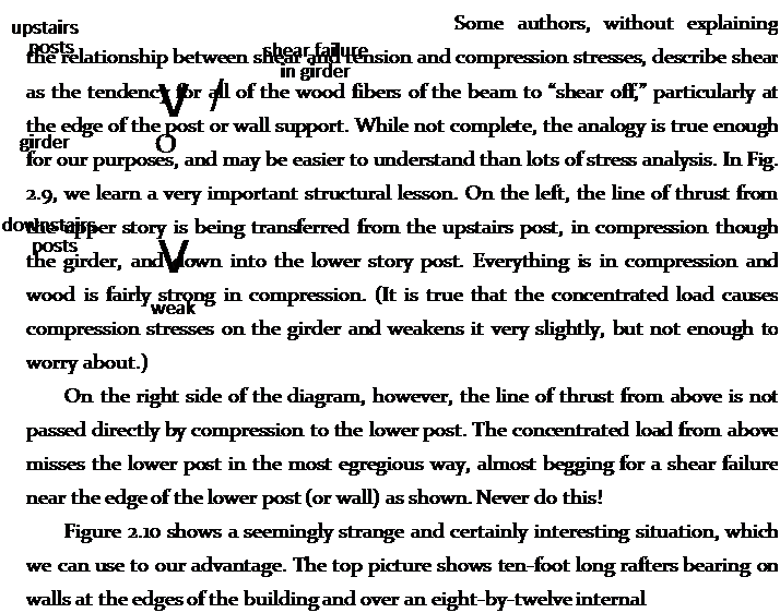
Fig. 2.9: The arrows indicate lines of thrust from the roof.


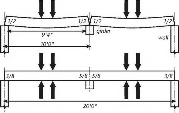
Fig. 2.10: Deflection is reduced with a double span as shown in the lower diagram, and bending strength is increased… but shear strength is decreases by about 25

percent.


image21

girder at the center of the building. If the rafters are bearing four inches onto the walls and girder, the clear span is actually 9 feet 4 inches (2.84 meters). In the bottom picture, we will use a 20-foot (6 meter) long rafter to do the same job.

The reader will probably not be surprised to learn that the situation at the top will promote more deflection in the rafters (deflection is discussed below) and will decrease the bending strength a little bit. The one-piece construction shown in the lower diagram “stiffens” the structure: greater bending strength and less deflection.

However — and this is the strange and interesting part — the structure at the top is actually stronger on shear. The structure in the lower part of the diagram has some very high shear stresses occurring on the top surface of the rafter where it passes over the girder. The effect of the sliding feature of the wood fibers over the neutral axis is increased, because the compression stresses on the top surfaces of the two spans are causing a tremendous tensile stress at the top of the rafter directly above the girder. Think of it: If the two spans are each trying to pull away from each other, because of the load on each span, those wood fibers at the top of the rafter (over the center) are working really hard not to break on tension. All of this translates to lower shear strength at this location. In the top picture, shear stresses over the supports are clearly the same at all four shear locations, expressed by the fractions V2 in each case. But, in the bottom picture, the shear stresses are expressed as 5Л at the walls at the right and left but increase to Vs where the long rafter is supported by the girder in the middle.

The upshot is that shear strength is gained by using two ten-footers instead of a single 20-footer supported in the middle. It is also true, as we have said, that bending strength is slightly diminished in the former example, and deflection is increased — but if the weak point in the engineering happens to be in shear, the former example may be better. This situation may work in our favor, when you consider that two ten-footers are much easier to handle — and certainly less expensive — than a single twenty-footer.

On Beams with a Round Cross-section, or Vigas

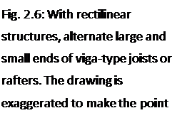
Подпись: Fig. 2.6: With rectilinear structures, alternate large and small ends of viga-type joists or rafters. The drawing is exaggerated to make the pointimage16

Many old barns and houses make use of floor joists and rafters that were made from locally grown straight tree trunks. Sometimes the builder would flatten one edge of the timber with an adz, so that roofing or flooring could be more easily nailed to it. In Mexico and the Southwest, exposed vigas (beams of round cross-section) are a common and attractive architectural feature.

Owner-builders today sometimes make use of their own home-grown timbers. They can be taken to a sawmill for squaring, they can be milled in the forest with a portable sawmill, or they can be barked and used in their natural round cross-sectional shape.

While this book is mostly concerned with the use of timbers milled on four sides, the author is in no way opposed to the use of viga-type beams, which can be quite beautiful. Here are some tips with regard to their use.

1. Choose sound straight trees for making vigas.

2. Remove the bark. The easiest time to do this is in the spring, when sap is rising. The greasy sap actually makes barking the wood very much easier, as it forms a slippery layer between the bark and the cambium wood layers. Good tools for barking include a pointed mason’s trowel, a straight hoe, or a peeling spud made from any piece of flat stock metal that has an edge sharpened. Barking at the wrong time of the year, such as autumn, may necessitate the use of a drawknife, which is a lot like hard work.

3. For the purpose of judging the strength of a viga, consider its small end as the sectional dimension. Remember the old saying that a chain is only as strong as its weakest link? This principle is often

appropriate with timber framing, where a mortise and tenon joint can actually reduce the shear strength of beams where they join a post. However:

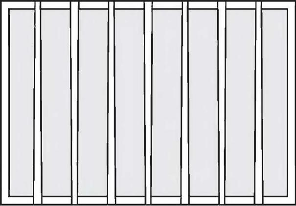
4. For maximum strength with rectilinear structures, alternate large and small ends on parallel rafters or joists, as per Fig. 2.6. This is different from the weakest link analogy, as the entire floor or roof is distributed over several parallel rafters and alternating weak and strong members lends greater strength to the entire structure. Stronger members assist weaker members.

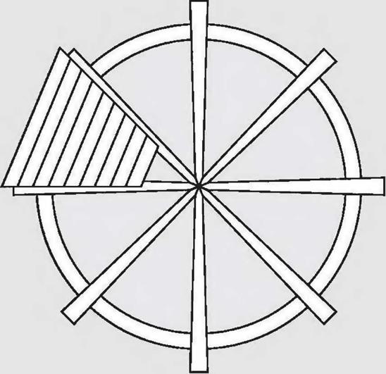
5. With a radial rafter system, where all the rafters or joists head towards the center, as in our round Earthwood house, put all the smaller ends towards the middle, where they are supported by a large post or a post- and-capital, as per Fig. 4.28. The frequency (space between members) is greater towards the center, so the strength there is naturally enhanced. The big ends are placed at the building’s circumference, where they

help to support the greater planking spans and their resultant loads. Fig. 2.7.

Incidentally, for beams with a round cross – section, like vigas, the section modulus is expressed as S = fTd3/32, or, simplifying constants, S = .09818d3. So, for a beam cut from a tree trunk with a small-end diameter of eight inches, we get a section modulus of.09818(8")3, or 50.27 inches cubed. A beam with a square cross-section, common with timber framing, has a section modulus of S = d3/6. So, for a full eight – by-eight, S = (8")3/6 = 85.33 inches cubed. I find it interesting that an 8" diameter log has so much less bending strength than an eight-by-eight timber. Also, the eight-by-eight is "stiffer." See the section on Deflection.

Fig. 2.7: With a radial rafter system, place the smaller end of the vigas over the center support post.


image17

Bending and Bending Failure

Yes, a good beam is a thing of beauty, but the main quality we are looking for in a beam is that it will not fail under the load we are asking it to carry. So we had better know a bit about the kinds of failures that can happen.

The failure in beams that people seem to grasp most easily is that of bending failure. If we keep loading a beam, particularly towards the middle of the span, we are placing ever greater bending stresses upon it. When we exceed the bending

Подпись: 2.5a Подпись: 2.5b strength of the beam, it will break, usually somewhere in the middle third of the span. This seems logical and natural, just as it seems natural that the two-by-eight plank described above is far more likely to break under a bending load if it is laid flat than if it is installed, properly, on edge. But common sense aside, it is useful to know why this is so from a structural or mathematical standpoint.
Because of a strength characteristic with the rather imposing name of section modulus, the depth (d) of the beam — the vertical dimension — has its value squared. But the breadth (b) of the beam carries only a regular linear value. For beams with rectilinear cross-sections, section modulus (S) is expressed: S = bd2/6. Interestingly, section modulus is solely a function of shape — geometry, if you like… and not a function of materials.

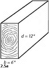
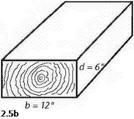
This strength relationship can be shown clearly if we look at the example of a timber with a 6-inch by 12-inch cross-section, because the constant — 6 — cancels out so conveniently. In Fig. 2.5a, we see a section of a six-by-twelve beam installed as it should be. The section modulus is the breadth (b, or 6") times the depth (d, or 12") squared, all divided by the constant 6. S = 6" X (12")2/6 = 144 inches cubed, the unit for section modulus (not to be confused with cubic inches.) On the bottom (Fig. 2.5b), the beam has been installed by a builder, who, to put it kindly, “is as thick as two short planks.” Now the breadth is 12 inches and the depth is 6 inches. So: S = 12" X (6")2/6 = 72 inches cubed. Now, mathematically, we can see that the beam is only half as strong in bending if we lay it down instead of standing it up correctly. I chose a six-by-twelve for easy math with whole numbers, but this relationship is true with any beam that is twice as deep as it is wide. With something like a two-by-ten joist, the difference is more extreme: the joist is five times stronger on bending installed “standing up” instead of “lying down.” The section modulus for a truly square beam or girder, like an eight-by-eight or ten-by-ten, can make use of the same formula, but as b and d are the same, it can be simplified to S = d5/6.

Compression and Tension in Beams

Beam is a good catch-all word to identify a (usually) horizontal timber whose job it is to carry a load across a span. Girders and floor joists are common specific examples, as are lintels over doors and windows. Even though many roof rafters are pitched to some degree, they perform as beams, too, although other thrust considerations come into play.

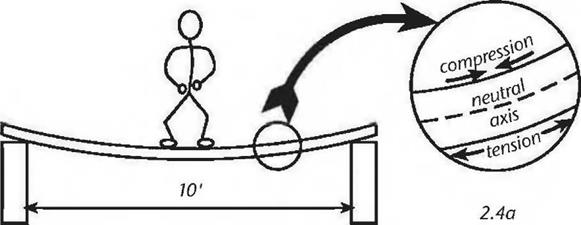
Let’s load a simple but imaginary beam to see how it works. We’ll make it a rather flimsy beam so that its exaggerated performance will show what’s happening. Imagine a 12-foot long two-by-eight plank spanning — flatwise — from one support to another. If the ends of the plank are each bearing on a foot­wide concrete block, the clear span between supports is ten feet. Now I’ll step on to the center of this “beam,” rather carefully, with my 170-pound weight. Obviously, the plank sags in the middle, and quite a bit. But it probably doesn’t break, even though it has me a little worried. What is happening is that the

underside of the plank is being stretched under my weight; that is, it is in tension. At the same time, the molecules on the top surface of the plank are trying to crush together; it is in compression.

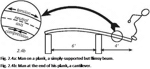
image12Подпись: Fig. 2.4a: Man on a plank, a simply-supported but flimsy beam. Fig. 2.4b: Man at the end of his plank, a cantilever. Allowing that this is true — and it is — it follows that an imaginary line along the center of the planks thickness is neither in compression nor tension. This line is known as the centroid or the neutral axis. See Fig. 2.4.
An imaginary beam as here described would be very springy, somewhat like a trampoline. Move one of the supports inward four feet, and we are on the way to

inventing both the cantilever and the diving board. Interestingly, when the beam is cantilevered by placing my weight at its free end, the top surface is now in tension and the bottom surface is in compression.

Instinctively, we know that to lay a “beam” flat like this is — well — stupid. Obviously, if the plank were rotated 90 degrees along its transverse axis — so that it looks like a proper floor joist — it would be very much stronger against bending pressures. It would feel quite stiff to walk along, providing I could maintain my balance for 10 feet. We may think that we know this instinctively, but I submit that it is a matter of our experience more than instinct.

Compression

Compression — in wood, not my father’s car engine — can be thought of as the tendency to crush or compress under a load. The actual crushing or compressing does not have to be measurable to be real. If 1 stand on a stout — say, 12-inch diameter by 12-inch high — oak chopping block, my weight puts that chopping block in compression, even though I am having no measurable impact upon it. My entire family could balance atop the block to no effect, yet the block is definitely in compression. It might seem that such a stout block would never fail under compression, and yet it can under extreme circumstances. In October of 2003, Jaki and 1 rotated a 20-foot long 20-ton stone on a 12-inch-wide pivot made of a dense hardwood, an incredible concentrated load. Yes, the pivot eventually failed — it was crushed and ruptured apart, finally — but we did manage to swing the stone through almost 90 degrees of arc before it did.

The stresses on posts or columns are due mostly to compression, particularly if the line of thrust from above is straight down through the center of the post, as in Figure 2.2a. (Our chopping block example, incidentally, is simply a short stout post.) However, if the line of thrust wanders out of the middle third of a post — or a wall — then the side of the post or wall where the load is concentrated is in compression, while the side away from it is in tension.

(Fig. 2.2b).


Fig. 2.2a: The line of thrust is in the middle third of the wall. The reactionary thrust is in compression.

Fig. 2.2b: The line of thrust has wandered into the outer third of the wall, still under compression, but the inner surface is on tension and the wall is unstable.

Fig. 2.2c: The line of thrust has left the confines of the wall, which now buckles and fails.


о


&

з

о


cu

c

c


Tension

Tension can be thought of as the opposite of compression. While comp­ression wants to squish the molecules of a material together, tension is trying


из


УЗ


1/3


1/3


1/3


1/3


Ar


Лг


2.2a


2.2b


2.2c


image7image8image9

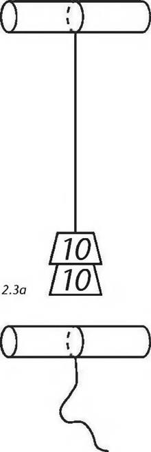
image10Подпись: 2.3bПодпись:image11to stretch the molecules apart. If I hang lead weights on a string, the string is in tension. If I keep adding more lead weights until the tensile strength of the string is exceeded, we will observe a failure in tension: the string breaks.
If the line of thrust actually leaves the edge of the support structure, as per Fig. 2.2C, the member will hinge somewhere along its height and something — like the upper story or the roof — will come crashing down.

While writing the above paragraph, I envisioned a building failing in the way described. It happens, particularly with old abandoned buildings under a severe load, such as heavy snow or strong wind. It occurred to me that the failed building lands up in some kind of an untidy heap, which, in and of itself, is actually a new structure, one designed instantly by the physics that apply near the surface of this planet. If you looked carefully at the resultant pile of twisted and broken timbers, you would see a structure with new lines of thrust being distributed along tension and compression, and by way of natural triangles and trusses. Such a pile might be weak, only able to support itself for a short time, or it might be surprisingly strong. An old barn building near us has been slowly receding into the landscape for 25 years.

We’ll talk more about posts later, but I think it would be helpful to consider beams first, because posts, surprisingly, share some of the same characteristics as beams.

Basic Timber Frame Structure

M

y father was a mechanical engineer. When we kids had difficulty learning how to coordinate the clutch with changing gears, he would explain to us the mechanics of what was actually taking place inside the transmission, and that seemed to make learning to shift a whole lot easier. We could visualize the nasty things that would happen if the clutch were not engaged before changing gears. You don’t need to know anything about clutches to build a timber frame, but in a similar way, knowledge about a few basic principles of structure will help you to prevent nasty things from happening to your building.

Load and Line of Thrust

Any structure has to support itself and anything that is added to it, such as furniture, people, earth, snow, even wind. All of these things fall under the general category of load, but the term should be broken down even further.

The dead load or structural load is the weight of the structure. First, a building must be able to support itself.

The live load is the total of the forces acting on the frame as a result of its use, such as furniture, people, items in storage, and the like.

The snow load is a specific live load, which varies from place to place. It is the weight of the maximum accumulation of snow that can be expected in your area. Check with the local building department. Plattsburgh, New York, for example, uses a snow load of 70 pounds per square foot (PSF).

Wind load is different in that it is not predicated upon weight. We can set it aside for a moment, but it is important and we will return to it in Chapter 4, page 75, under the heading Wind Can be a Serious Problem.

Those living in earthquake zones will need to consider yet another load, a lateral live load that occurs as a building oscillates during a tremor. In a severe

• 15

quake, this lateral load can be more severe than wind loading. Check with your local building department if you live in a seismic zone.

The resultant or combined load is the total effect and resulting direction of all of the various loads that act on a structure. We’ll see an example of this when we discuss the several different loads on an earth roof.

Sam Clark, author and professional builder, explains the business of a structure in a very clear way:

Подпись: Fig. 2.1: The various loads in this structure put great strains on the jointing. The line of thrust — marked L/T — transfers the resultant load most easily by spreading the sidewalls. This event is simply a matter of time and could even happen during construction.To withstand the loads on it, a house structure must meet three criteria. One, the individual members of the structure, such as beams, joists, and studs, must be strong enough. Two, the members must be attached to one another properly. The joints must be strong. Three, the lumber must be assembled so that the structure as a whole is rigid. (Clark, 1996.)
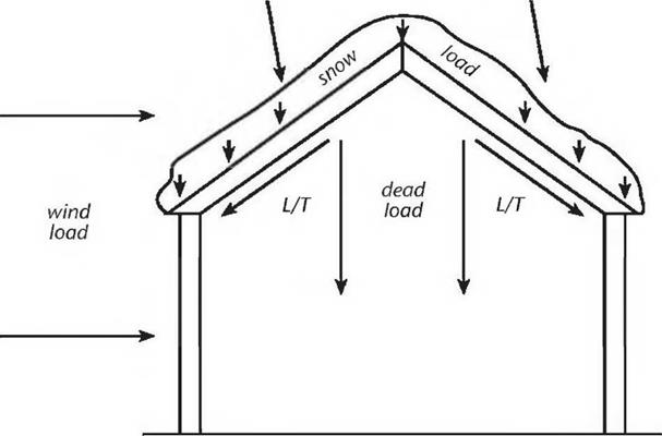
A term frequently used in discussions of stress in structure is the line of thrust or thrust line, which can be thought of as the transfer of a load. Structural design deals with thrust lines so that the building is kept in a state of static equilibrium, which, with timber framing, often consists of balancing compression and tension forces.

Figure 2.1 shows the various loads on a section of a simple gable-roofed structure. With the exception of the wind load, most of the line of thrust from the

Подпись: resultant or combined load image6roof is downward, following gravity. But the weakness of such a building is in its joints: the connection between rafters or roof surfaces at the ridge, and the connection of the rafters or roof surface with the posts or sidewalls.
As drawn, the combined roof load will impart tremendous lateral stresses on the sidewalls, causing them to spread and, ultimately, to fall over, as shown in Fig. 4.37a, on page 88 of Chapter 4. Neither the most skilled timber joinery nor the best metal connectors can be expected to last long under these circumstances. The problem is bad design.

While you’ve got your finger on page 88, check out Figures 4.37b and 4.37c, which show two good ways to make this weak structure much stronger. We’ll revisit these particular structural considerations, as they relate to actual building, in Chapter 4.


. Structural Insulated Panels

“Traditional” Timber Framing

I use the term “traditional” timber framing to describe the system of joining timbers to each other without benefit of metal or mechanical fasteners. Typically, posts, girders, rafters, king and queen pins, etc., are connected to each other by the use of time-tested joinery such as mortise and tenon joints, scarf jointing, dovetails, rabbetting, etc. A good example of traditional timber framing is seen in Figure 2.17, in the next chapter.

In most cases, one or more people will lay out the various sides, gable ends, and “bents” (internal wall framing or other internal structural assemblies) on the ground. Time and care are taken to join the various heavy timbers by one of the many clever and intricate joints that have evolved over the centuries. Sometimes, particularly with owner-builders, a completed section will be raised with the help

of friends, so that there is room on the site (or foundation slab) to build the next component. Alternatively — and this is more common with experienced timber frame builders — the entire barn or house frame may be erected in a single day Professionals often manufacture all of the components in a shop environment, making sure that the pieces fit together properly, and then reassemble the frame on site.

Although traditional timber frames are sometimes used with natural infill alternatives, they are more commonly built to support pre-made insulated panels on the exterior, with wooden siding installed later. The fine joints are in evidence on the internal skeleton of heavy timbers, a beautiful and impressive effect. Spacing of vertical members is more critical when applying manufactured stress skin panels than it is when a natural infilling is used between posts. See Appendix C and the Bibliography for resources about stress skin panels, and structural insulated panels.

Done professionally, traditional timber framing can be quite expensive because of the labor and materials cost, but good timber framers are worth every cent they get in terms of quality. Owner-builders can do the work, too, but developing and using the required skills will add very much more time to the project. I am an experienced owner-builder, but I would certainly take a two-week course at one of the building schools before embarking on a traditional timber­framing project.

Timber Framing for the Rest of Us

Strong, functional, and attractive timber-framed buildings are made by farmers, carpenters, and owner-builders throughout the world, and only a small proportion of these projects involve traditional timber framing. Most of these rural buildings — even houses, when heavy timbers are used — involve the use of truss plates, joist hangers, pole-barn nails, log cabin spikes, gravity, screws, bolts and ingenuity. These builders learn from their neighbors, family, local builders, and sometimes just by asking advice at the local sawmill or lumberyard. It’s sort of like the way beavers and other building species learn their trade.

But sometimes it’s hard to find someone to help on the project, so here we are. Now we need to talk about some basic structural principles.

Timber Framing: Advantages and Disadvantages

Whether you go with “traditional” timber framing (which the Timber Frame Guild likes to call “contemporary timber framing”) or “timber framing for the rest of us,” certain advantages and disadvantages are common to both systems.

Strength. Timber framing by either method is strong. It is not only strong in real structural terms, but it exudes a sense of strength in the architecture. It is hard to visit a half-timbered framed house or country pub in England and not be impressed with the atmospheric power of the structure, a power that owes much of its strength to the visual impact of the beautiful exposed timbers, especially the big old gnarled ones.

Heavy-timber frames, with or without infilling, are more resistant to trauma from earthquakes, wind uplift, and snow load than light-frame construction. In areas prone to these natural calamities, care must be taken to meet local building code with regard to tying the frame to the foundation, as well as the roof to the frame.

Conducive to infilling. As already stated, heavy-timber framing is more appropriate than stick framing as regards infilling with the various natural building methods popular today. With infilling, it is not critically important that exactly 14У2 inches (36.8 centimeters) is left between vertical members, either studs or posts. Masonry and cob can fit any space. Straw bales can be made to fit

almost any width of space, too, if the baling twine is retied as described in various straw bale construction manuals.

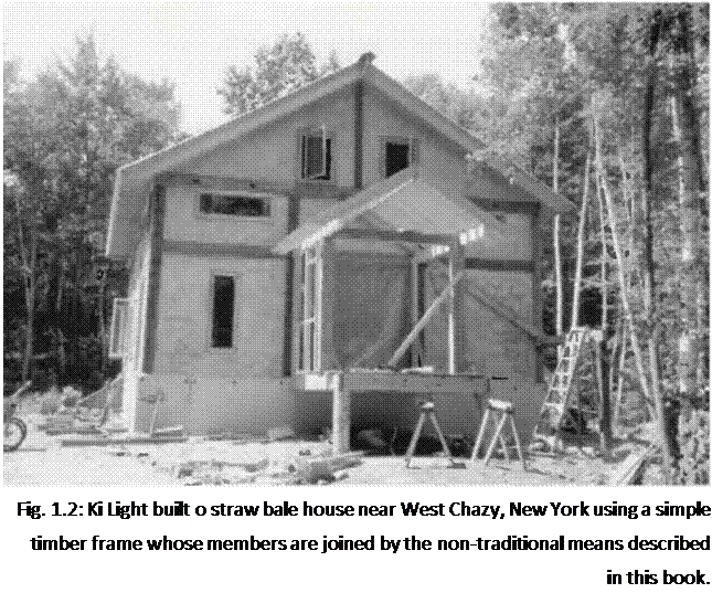
Подпись: Fig. 1.2: Ki Light built о straw bale house near West Chazy, New York using a simple timber frame whose members are joined by the non-traditional means described in this book. Esthetic appeal. Normally, timber frames are left exposed, either on the interior, the exterior, or, in many cases, on both sides of the wall, such as the guesthouses and the garage at Earthwood. With many of the professionally built contemporary timber frame houses, structural insulated panels are fastened to the outside of the frame, and the beautiful heavy timbers are left exposed on the interior, (see Sidebar on page 13) At some 16-sided cordwood homes, the heavy timbers are in evidence on the exterior, but not on the interior. Chapter 6 of my previous book Cordwood Building: The State of the Art [see Bibliography] contains a detailed description of this almost-round timber frame. The method is of most interest to cordwood masonry builders, and is not repeated in this work.
In all cases, the exposed timbers lend character, texture, and an esthetic sense of strength to the architecture. All of this translates into comfort, spiritual and otherwise.

Ease of construction. If you’ve never built anything before, you might actually find timber framing to be easier than conventional studding, which requires fairly exact tolerances for the application of sheetrock, plywood and the like. With timber framing, there are far fewer pieces to handle. And tolerances, at least in the post and beam frame, do not need to be quite so exact, particularly when the walls are infilled with natural materials. True, much of the work will require two people, but this is also true with stick-frame construction.

Economy. If you are buying from a local sawmill or a farmer, or if you are making timbers from your own trees, timber framing is almost certain to be more economical than buying finished lumber. When buying heavy timbers from a distant source, this advantage is lost and timber framing may become more expensive. The key to building anything economically by any method is to use local or indigenous materials.

Making the Grade

Подпись: Upon hearing that I planned to build a timber frame home with an earth roof, the immediate response from the building department supervisor was, "Are you a structural engineer? I'm not." I knew then that I would have to hire an engineer. But another problematic issue soon arose, revolving around the fact that I was felling my own trees (hardwood, no less) and chainsaw-milling them into posts and beams. The issue concerned the use of ungraded hardwood lumber. Finding an engineer was a process by itself, as I encountered resistance to the idea of using native timbers. Many engineers simply don't want to be bothered with "gray" areas when it comes to what they think of as unconventional building. Tracking down someone to grade my homespun hardwood timbers was even more difficult than finding the right engineer. We live in the northern part of Michigan's lower Peninsula. Numerous local sawmills process the fine maple, oak and beech stands in our region, but none of the ones I contacted graded hardwood for its structural properties, but only with respect to veneer lumber, flooring, and the like. I contacted a "certified" hardwood lumber grader through one of the mills, who made a 90-mile round trip to my place only to reveal that he didn't know how to grade posts and beams for structural purposes. So I cast my net further afield. Подпись: The Department of Forestry at Michigan State University referred me to the National Hardwood Lumber Association (NHLA) in Memphis, Tennessee. Through them I connected with a sympathetic inspector who proposed an alternative to having him visit my location and charging me the minimum fee of $470 a day, plus expenses. He volunteered to call the local "certified" inspector — the one who had already visited — and explain to him how to grade hardwood for structure. The grading was done according to guidelines from the Northeastern Lumber Manufacturers Association (NeLMA) in Maine. The inspector charged me $120 and apologized that the bill came to that much. It seemed quite reasonable to me, considering the time he spent educating himself to "make the grade." Incidentally, the building inspector was not the only one who needed the certified grading; my engineer also needed it in order to feel comfortable about assigning values to my timbers. Thankfully, my building inspector is basically on my side and seems to appreciate the lengths I've gone to satisfy code. I've maintained a cordial relationship with all the inspectors I've dealt with, and though it's been mighty frustrating at times, the good will is generally repaid in kind. It pays dividends to treat the building department as a resource, and not an adversary.

Mark Powers, owner-builder, Alonson, Michigan

Author’s note: The two lumber organizations mentioned above, NHLA and NeLMA, are listed in Appendix C.

In short, the grading of lumber can be an expensive proposition, which defeats the advantage of using local rough-cut lumber in the first place. At this time, despite widespread adaptation of the International Building Code, it is possible for most people in rural areas to build with non-graded lumber. Check on this with the town or county building inspector before placing a big lumber order with your local sawmill, or cutting quantities of your own lumber with a chainsaw mill. If evasion is a strategy that you have in mind — I am not advocating this, you understand — then you might want to gain the information anonymously.

My guess is that wherever the local forest products industry is strong, there will be (or soon will be) provisions such as the one recently adopted by New York to allow the use of rough-cut lumber. Economic considerations aside, you cannot easily purchase heavy timbers from ordinary building supply yards. Local sawmills, farm sawmills, and personal timber cutting (small chainsaw or bandsaw mills) are the realistic and affordable choices, and these are discussed in Chapter 3.