Fastening the Timber Frame to the Foundation
Whatever foundation method is selected, local codes will vary on their requirements for tying the timber frame down to it, depending on the likelihood of hurricanes, tornadoes and earthquakes. In most areas, a heavy timber frame will not vertically leap off of the foundation so the main consideration is to prevent the sill plate or the posts from moving laterally. This is most easily accomplished by joining the posts to the foundation with positioning pins. As northern New York does not suffer from any of the aforementioned natural disasters, this is what I have been doing with all our buildings since 1975.
The joint between posts and foundation. Sometimes just the posts are fastened to the foundation, and infilling (such as cob, cordwood, or straw bale) completes the wall between posts after the frame is completed, such as La Casita in Fig. 4.2. Our downstairs doorposts at Earthwood are also pinned direcdy to the foundation. I pour the footings or the floating slab without placing positioning pins (anchor bolts) in the concrete, for two reasons: 1) It is difficult to trowel the concrete smoothly within a few inches of the anchor bolt, leaving an irregular bearing surface for the post to stand upon and 2) Murphys Law tells you that the pin or anchor bolt will not be in the right place when you come to use it, particularly with doorframes.
Therefore, I install my positioning pins in another way. After the concrete has set — it is hard and strong after two weeks — I use a carbide masonry bit to drill holes into the concrete exactly where they should be. I can measure off the corners and double-check my measurements. These holes are drilled the same depth as the length of the expansion shield which will be later driven into them. These cylindrical shields, available at any building supply store, are made of lead and are split in half to receive a certain size lag screw. The shield has all the pertinent information molded right into the lead. For example, you might see D, %S’’embossed in the lead. This tells you to drill the hole with a five-eighths-inch (1.6 centimeter) Drill bit, and that you will insert a three-eighths-inch (1.0 centimeter) screw into the shield later. Drill the hole a smidgen deeper than the length of the shield. I find two-inch (5.0 centimeter) shields to be convenient: not too much drilling, but plenty strong enough. Blow the dust out of the hole with a straw, but wear eye and nose protection.
The shields are driven into the clean hole with a hammer so that the top of the shield is flush with the concrete surface. Next, turn the hex-headed lag screw into the shield with a socket wrench until the screw is tight. Choose a length so that when the hex head is cut off (takes 30 seconds with a hacksaw), about two inches will be left exposed above the concrete. If you use a two-inch shield, then, you will want to buy four-inch lag screws.
There is another fastener that will do this job a little more easily and has the advantage of leaving a threaded end proud of the foundation, for the installation of angle iron as a fastening aid or for the installation of sill plates (described below.) Simpsons fastener of this kind is called an “Easy-Set pin drive expansion anchor,” quite a mouthful, so just ask the clerk for an expansion anchor or strike bolt. A pin sticks out of the anchor, and when the pin is struck, the anchor expands tightly into the hole. So, again, drill a hole (Simpson recommends a hole one-sixteenths-inch greater than the anchor diameter), insert the anchor, and give the pin a good blow with a hammer. Choose a length of strike bolt appropriate for the application. For most purposes, leave the top of the anchors shaft extending two inches proud of the foundation. The downside of strike bolts is that they are about three times as expensive as the expansion shield method, so I still use the shields and lag screws. They don’t call me Rob Roy for nothing.
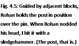
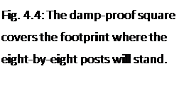
Now, before installing the post, there is a very important step which must not be omitted. Cut a square of material — called, by the Brits, a “damp-proof course”— the same size as the footprint of the post. An eight-by-eight post requires an eight-inch by eight-inch (20 by 20 centimeter) square of damp-proof material. I have used pieces of asphalt shingle as well as 240-pound roll roofing for the purpose, both successfully. These materials are almost an eighth of an inch thick. Before placing the posts, position the square of asphalt over the anchor pin and press down. Sometimes you can actually press the square down over the pin right to the foundation. Sometimes, you may have to make an impression and actually cut the little hole out with a knife. In either case, you will now have the post’s footprint completely covered to prevent “rising damp.” This protects the underside of the post from deterioration by damp and rot. Believe me, it works. I have done this for 25 years with no deterioration in any post or doorframe. (The International Residential Code at Section R323 also requires “an impervious moisture barrier,” wherever a wooden post meets concrete.) I have seen others put the post directly on the concrete without the square of asphalt damp proofing, and those posts have deteriorated badly. Plus, the almost eighth-inch thick piece
acts as a steadying or leveling influence when it comes to actually standing the post in place.


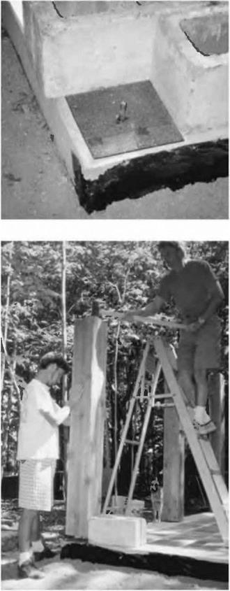
 Erecting an individual post is a two-person, two-step process, because of the positioning pin. First, the post is stood up onto the pin. Concrete blocks can be used as positioning aids so that you know that the post will stand on just the right footprints, as seen in Figs. 4.4 and 4.5. Make sure that the post is the right length and has two good squared ends. Now, while one person holds the post, the other person, on a stepladder, gives it one stiff “thwack” with a heavy hammer, making an imprint on the underside of the post. Next, the post is taken down and a hole of the same diameter as the threaded lag screw is drilled at least as deep as the pin is high, say two inches in our example. Finally, the post is stood up again, but this time it is there to stay, the pin in the hole keeping it in the right place, even during an earthquake.
By the one-post-at-a-time method, each post must be supported in two different directions by long diagonal scrap timbers, nailed to wooden stakes pounded firmly into the ground. (If the post is in the middle of a slab, or at some intermediate point along the wall, horizontal pieces of flat scrap, such as two-foot long (61 centimeter) pieces of two-by-four, can be screwed to the bottom of the post to act as stabilizers. A piece of plywood in the shape of an isosceles triangle will work nicely, too. Review figure 2.21).


Leave a reply