Basic Timber Frame Structure
|
M |
y father was a mechanical engineer. When we kids had difficulty learning how to coordinate the clutch with changing gears, he would explain to us the mechanics of what was actually taking place inside the transmission, and that seemed to make learning to shift a whole lot easier. We could visualize the nasty things that would happen if the clutch were not engaged before changing gears. You don’t need to know anything about clutches to build a timber frame, but in a similar way, knowledge about a few basic principles of structure will help you to prevent nasty things from happening to your building.
Any structure has to support itself and anything that is added to it, such as furniture, people, earth, snow, even wind. All of these things fall under the general category of load, but the term should be broken down even further.
The dead load or structural load is the weight of the structure. First, a building must be able to support itself.
The live load is the total of the forces acting on the frame as a result of its use, such as furniture, people, items in storage, and the like.
The snow load is a specific live load, which varies from place to place. It is the weight of the maximum accumulation of snow that can be expected in your area. Check with the local building department. Plattsburgh, New York, for example, uses a snow load of 70 pounds per square foot (PSF).
Wind load is different in that it is not predicated upon weight. We can set it aside for a moment, but it is important and we will return to it in Chapter 4, page 75, under the heading Wind Can be a Serious Problem.
Those living in earthquake zones will need to consider yet another load, a lateral live load that occurs as a building oscillates during a tremor. In a severe
• 15
quake, this lateral load can be more severe than wind loading. Check with your local building department if you live in a seismic zone.
The resultant or combined load is the total effect and resulting direction of all of the various loads that act on a structure. We’ll see an example of this when we discuss the several different loads on an earth roof.
Sam Clark, author and professional builder, explains the business of a structure in a very clear way:
 To withstand the loads on it, a house structure must meet three criteria. One, the individual members of the structure, such as beams, joists, and studs, must be strong enough. Two, the members must be attached to one another properly. The joints must be strong. Three, the lumber must be assembled so that the structure as a whole is rigid. (Clark, 1996.)
A term frequently used in discussions of stress in structure is the line of thrust or thrust line, which can be thought of as the transfer of a load. Structural design deals with thrust lines so that the building is kept in a state of static equilibrium, which, with timber framing, often consists of balancing compression and tension forces.
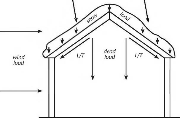
Figure 2.1 shows the various loads on a section of a simple gable-roofed structure. With the exception of the wind load, most of the line of thrust from the
![]()
 roof is downward, following gravity. But the weakness of such a building is in its joints: the connection between rafters or roof surfaces at the ridge, and the connection of the rafters or roof surface with the posts or sidewalls.
As drawn, the combined roof load will impart tremendous lateral stresses on the sidewalls, causing them to spread and, ultimately, to fall over, as shown in Fig. 4.37a, on page 88 of Chapter 4. Neither the most skilled timber joinery nor the best metal connectors can be expected to last long under these circumstances. The problem is bad design.
|
|
|
|


Leave a reply