Shear and Shear Failure
Shear failure is much more difficult to envision than bending failure. In fact, with light frame construction, shear failure seldom comes into play, whereas it is an important consideration for heavy timber framing, particularly with a very heavy load such as an earth roof or a steam train.
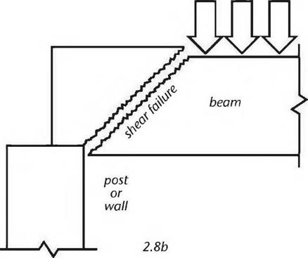
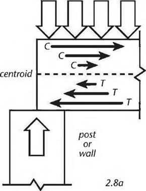
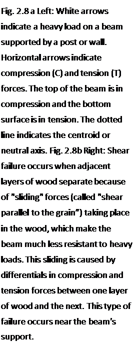 One good way of explaining shear is to think of it as a combination of compression and tension stresses. Remember that the top surface of a beam is in compression, the bottom surface is in tension, and the centroid (middle part of the beam) is neutral (thus also called the neutral axis.) Fig. 2.8a shows the compression and tension forces at one end of a beam, where it is supported over a post or wall. The arrows show the compression and tension forces. Note that the arrows are pointing in opposite directions, and that the strength of the compression or tension forces diminishes closer to the neutral axis. Fig. 2.8b shows the kind of failure that can happen when the stresses in the beam cause the wood fibers to slide along each other at varying rates. Not surprisingly, the separations often follow annual growth rings. This is why woods prone to shake, such as hemlock, are also low in shear strength. (Shake is the term for a weakness in wood caused by separations between annual growth rings.) It is no coincidence that if a two-by-six hemlock plank is tossed too casually to the ground, it will shatter parallel to the grain.
|

 |
|
|
|
|
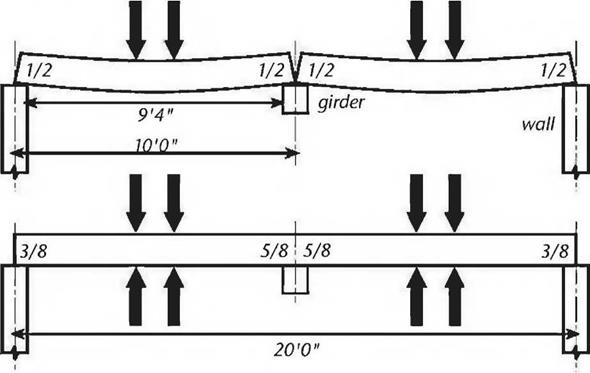
girder at the center of the building. If the rafters are bearing four inches onto the walls and girder, the clear span is actually 9 feet 4 inches (2.84 meters). In the bottom picture, we will use a 20-foot (6 meter) long rafter to do the same job.
The reader will probably not be surprised to learn that the situation at the top will promote more deflection in the rafters (deflection is discussed below) and will decrease the bending strength a little bit. The one-piece construction shown in the lower diagram “stiffens” the structure: greater bending strength and less deflection.
However — and this is the strange and interesting part — the structure at the top is actually stronger on shear. The structure in the lower part of the diagram has some very high shear stresses occurring on the top surface of the rafter where it passes over the girder. The effect of the sliding feature of the wood fibers over the neutral axis is increased, because the compression stresses on the top surfaces of the two spans are causing a tremendous tensile stress at the top of the rafter directly above the girder. Think of it: If the two spans are each trying to pull away from each other, because of the load on each span, those wood fibers at the top of the rafter (over the center) are working really hard not to break on tension. All of this translates to lower shear strength at this location. In the top picture, shear stresses over the supports are clearly the same at all four shear locations, expressed by the fractions V2 in each case. But, in the bottom picture, the shear stresses are expressed as 5Л at the walls at the right and left but increase to Vs where the long rafter is supported by the girder in the middle.
The upshot is that shear strength is gained by using two ten-footers instead of a single 20-footer supported in the middle. It is also true, as we have said, that bending strength is slightly diminished in the former example, and deflection is increased — but if the weak point in the engineering happens to be in shear, the former example may be better. This situation may work in our favor, when you consider that two ten-footers are much easier to handle — and certainly less expensive — than a single twenty-footer.


Leave a reply