Blog Archives

FIXTURE-UNIT TABLES

Fixture-unit tables are often used when sizing drains and sewers. The table in Figure 4.1 is an example of a table that expresses the maximum number of fix­ture units allowed on pipes of various sizes and with various amounts of fall. Before we go on, look at the category for 3-inch pipe, at a V4-inch per foot fall. It says that you are allowed 27 drainage fixture units. But, notice the lit­tle number 2 next to the number of fixture units. That number indicates a note or exception. When you look at the bottom of the table, you will see that the note tells you that not more than two water closets can be carried on a 3-inch pipe. There are exceptions, but if you stick with this rule, you can’t go wrong. This is one of the tables that I was telling you about earlier.

Diameter of pipe

read more

Contact Filter Paper Techniques

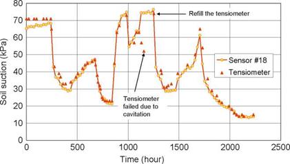
Although far less common than in the laboratory, techniques for in-situ matric suc­tion measurements using the contact filter paper (CFP) method and in-situ total suction measurements using the non-contact filter paper method have also been described (Greacen et al., 1989). The filter paper technique is, in theory, applicable over the entire range of total suction, but the method tends to be impractical for both extremely high and extremely low suction values. Reliable measurements tend to be limited to a range spanning about 0-10 MPa matric suction for the contact filter paper techniques and between 1 to 10 MPa of total suction for the non-contact technique.

The filter paper method is used as an indirect means of measuring soil suction...

read more

Extreme-value distributions

Hydrosystems engineering reliability analysis often focuses on the statisti­cal characteristics of extreme events. For example, the design of flood-control structures may be concerned with the distribution of the largest events over the recorded period. On the other hand, the establishment of a drought- management plan or water-quality management scheme might be interested in the statistical properties of minimum flow over a specified period. Statistics of extremes are concerned with the statistical characteristics of Xmax, n = max{X1, X2,…, Xn} and/or Xmjn,„ = min{X1, X2,…, Xn} in which X1, X2,…, Xn are observations of random processes...

read more

. FROM PLANS TO PLATES

Подпись:—4-

Chalklines are snapped on the floor to show the location of all the walls. The top and botzom plates will be tacked to the deck along those lines.

. FROM PLANS TO PLATES

plates temporarily tacked together on the sub – floor, you can mark up the plates to identify exactly where each stud, king stud, header, and trimmer is located. If you haven’t already done so, take the time to familiarize yourself with the various parts that go into a wood-frame wall (see the illustration on p. 84).

Mark wall layouts

Three marking tools are essential: a chalkline, keel, and a carpenter’s pencil. A chalkline and an ample supply of chalk allow you to snap exterior and interior wall layout lines on the

4

sublloor or slab (see the photo on p. 78)...

read more

PNEUMATIC NAILERS

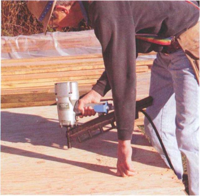
My first pneumatic tool drove only sta­ples, and I used it to nail subfloor and roof sheathing. Today, pneumatic nailers drive many types of fastener. In some areas of the country, they are almost as common on job sites as hammers.

What makes a pneumatic nailer so appealing is its speed. The nails are automatically fed into the nailer from a clip or coil (which can hold 200 nails or more), so you don’t have to keep reach­ing into your tool belt for nails.

Today, there’s a nailer for every job, from rough framing to roofing to the finest finish work. I own two framing nailers, a finish nailer, and a palm nailer. Both framing nailers drive 8d or 16d nails (see the photo below)—one feeds the nails from a clip, and the other feeds them from a coil. Both fit well in my hand,

PNEUMATIC NAILERS

A fram...

read more

DRAIN-AND-SEWER CALCULATIONS

D

oing calculations for drains and sewers is similar, in principle, to what you will use for vents in the next chapter. The process involves fixture units, the developed length of piping, sizing tables, and so forth. Pay­ing attention to details is an important element in designing any type of sys­tem, and this certainly holds true when sizing drains and sewers. Moving too quickly and using the wrong sizing table can cause you a lot of trouble. When work is simplified, it sometimes seems so simple that it is taken too lightly. Don’t make mistakes by not paying attention to footnotes and exclusions when you use sizing tables. If you read the tables carefully and apply them properly, sizing is not difficult.

Подпись:Some plumbers get so accustomed to using sizing tables that they fail to thi...
read more

On the river to Nubia, navigation works on the Nile (IIIrd and IInd millennia BC)

Navigation canal at the first cataract

Nubia is rich in quarries, and in gold and amethyst mines. A concerted effort to exploit these resources of the south began in the VIIth Dynasty, under the ancient Empire. But the Aswan rapids, comprising the first cataract of the Nile (Figure 3.4), present an obsta­cle to navigation. In about 2400 BC the Pharaoh Merenre I has his close lieutenant Ouni build a flume system to allow boat passage through this obstacle. Ouni, who later becomes governor of Upper Egypt, had his autobiography engraved in his tomb, where one can read the following:

“Then His Majesty sent me to dig five canals (flumes?) in Upper Egypt and to construct three

barges and four transport boats, from acacia wood of the land of Ouaouat. The chiefs of the

lands of Ouaouat, Iam and...

read more

Suction Plate

A simple laboratory variant of the tensiometer method for measuring matric suction of fine-grained soils uses a semi-pervious sintered glass plate. A small soil sample

Suction Plate

Fig. 3.15 Comparison between laboratory soil suction measurements with tensiometers and TCS. Reproduced with permission of D. Fredlund

is placed on the glass plate and covered immediately with a cap so that the vapour pressure around the soil comes to equilibrium with the suction in the soil, preventing drying. On the other side of the plate de-aired water is provided in a small chamber. The soil attempts to suck water across the glass plate from the chamber but the only way this can happen is by water being drawn into the chamber via a narrow-bore tube...

read more

Part iii: Shape of Particles of the Coarse Aggregate Fraction

The shape of the aggregate particles, from flat and elongated to cubical ones, exer­cises a certain influence on the SMA mixture. A high content of flat and elongated particles has the following effects:

• Increases the content of air voids in a compacted mixture of coarse (active) aggregates

• Decreases the workability of a mixture

• Increases the risk of fat spots appearing when compacting the SMA course

In the German DAV handbook (Druschner and Schafer, 2000), attention has been paid to the impact of the shape of particles from the fraction 2/5.6 mm on the content of voids in SMA, especially with reference to the SMA mixtures 0/8 and 0/8S.

read more

Step 10-Install Nail-Flange Windows

Before Wall is Stood Up

a. Check plans for correct window.

b. Check window opening for protrusions (nails, wood splinters, etc.) that might hold window away from edge.

c. Install window flashing. (See “Window Flashing Installation," Chapter 6.)

d. Set window in opening, making sure window is right side up.

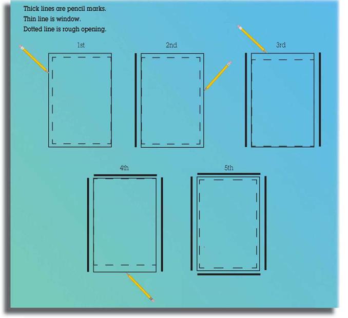
e. Slide window to each end of opening, and draw a line on the sheathing or flashing with a pencil along the edge of window. (Draw lines before caulking window.)

f. Center window in marks you have just drawn.

g. Nail window sides and bottoms, using appropriate nails.

h. Do not nail top of window.

Step 10-Install Nail-Flange Windows

11: Stand wall.

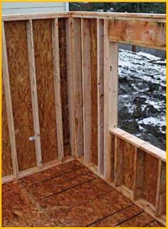
12: Set bottom plate. 13: Set double plate. 14: Set reveal.

Step 10-Install Nail-Flange Windows
Step 10-Install Nail-Flange Windows15: Nail wall.

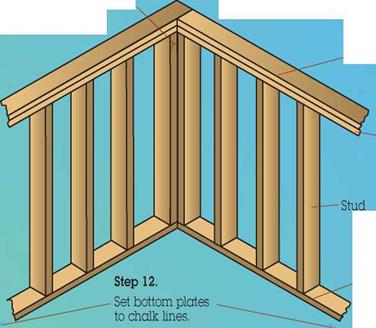
Подпись: The reveal is the amount of space on the corner stud of a wall after another wall is joined to it.Подпись:Подпись: Double plateПодпись: Step 15. Nail walls together, and nail bottom plate. Подпись:Подпись: Bottom plateStep 10-Install Nail-Flange Windows

Nail the end stud to set the reveal* in the middle of the wall where the two walls join...

read more