FIXTURE-UNIT TABLES
Fixture-unit tables are often used when sizing drains and sewers. The table in Figure 4.1 is an example of a table that expresses the maximum number of fixture units allowed on pipes of various sizes and with various amounts of fall. Before we go on, look at the category for 3-inch pipe, at a V4-inch per foot fall. It says that you are allowed 27 drainage fixture units. But, notice the little number 2 next to the number of fixture units. That number indicates a note or exception. When you look at the bottom of the table, you will see that the note tells you that not more than two water closets can be carried on a 3-inch pipe. There are exceptions, but if you stick with this rule, you can’t go wrong. This is one of the tables that I was telling you about earlier.
|
Diameter of pipe |
Fall in |
inches per foot |
||
|
(in) |
‘/ні |
% |
‘/4 |
‘/2 |
|
2 |
21 |
26 |
||
|
2 Vi |
24 |
31 |
||
|
3 |
202 |
272 |
362 |
|
|
4 |
180 |
216 |
250 |
|
|
5 |
390 |
480 |
575 |
|
|
6 |
700 |
840 |
1000 |
|
|
8 |
1400 |
1600 |
1920 |
2300 |
|
10 |
2500 |
2900 |
3500 |
4200 |
|
12 |
3900 |
4600 |
5600 |
6700 |
|
15 |
7000 |
8300 |
10,000 |
12,000 |
|
‘Includes branches of the building drain. The minimum size of any building drain serving a water closet shall be 3". “Not over two water closets. |
FIGURE 4.1 ■ Allowable fixture-unit loads. (Courtesy of McGraw-Hill)

|
|||||||||||||||||||||||||||||||||||||||||||||||||||||||||||||||||
|
|||||||||||||||||||||||||||||||||||||||||||||||||||||||||||||||||
|
|||||||||||||||||||||||||||||||||||||||||||||||||||||||||||||||||
|
|||||||||||||||||||||||||||||||||||||||||||||||||||||||||||||||||
|
|||||||||||||||||||||||||||||||||||||||||||||||||||||||||||||||||
|
The table in Figure 4.1 is easy enough to understand. If you find the size of the pipe you are working with, you can quickly ascertain the number of fixture units allowed on the pipe at a given grade. When you know the number of fixture units and the grade of the pipe, you can tell what size pipe is suitable. For example, a 4-inch sewer that is installed with a grade of one-quarter of an inch per foot can handle up to 216 fixture units, and that’s a lot of drainage. Upgrading to a 6-inch pipe with the same grade will allow you to load the pipe with 840 drainage fixture units. That’s all there is to that table.
![]()
![]()
 The listings in Figure 4.2 are comprehensive and easy to understand. For example, a residential toilet is assigned a fixture-unit rating of four. A typical lavatory has a rating of one fixture unit. Domestic shower stalls are rated for two fixture units. If you add this up, you find that the three normal bathroom fixtures total a rating of seven fixture units. However, if you look at the top of the list, you will see that a bathroom group that consists of a toilet, lavatory, and bathtub or
 shower has a rating of 6 fixture units. Wait a minute, that’s one fixture unit less than the individual ratings for the same fixtures. What gives? In this case, assuming that all of the fixtures were being placed in the same bathroom, you could use the lower of the two ratings. Why? Because it is assumed that not all of the fixtures will be being used simultaneously if they are confined to a single room. The use of a table, like the one in Figure 4.2, makes sizing drains a lot easier.
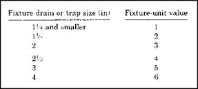
There may be times when the fixture that you are seeking a rating for will not be listed on a fixture-unit table. If this is the case, you can use a table, like the one in Figure 4.3, to assign a rating for fixture units. For example, a fixture with a 2-inch drain that is not otherwise listed would be
|
|
|||||||||||||||||||||||||||||||||||||||||||||||||||||||||||||||||||
|
|||||||||||||||||||||||||||||||||||||||||||||||||||||||||||||||||||
|
|||||||||||||||||||||||||||||||||||||||||||||||||||||||||||||||||||
|
|||||||||||||||||||||||||||||||||||||||||||||||||||||||||||||||||||
|
|||||||||||||||||||||||||||||||||||||||||||||||||||||||||||||||||||
|
|||||||||||||||||||||||||||||||||||||||||||||||||||||||||||||||||||
|
|||||||||||||||||||||||||||||||||||||||||||||||||||||||||||||||||||
|
|
FIGURE 4.6 ■ Trap-to-vent distances. (Courtesy of McGraw-Hill) |
several of the ratings are marked with exclusions. This is the type of detailed information that you must be on the lookout for.
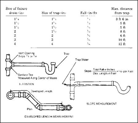
Suppose you are concerned about sizing a vent stack that will accommodate wet-vented fixtures? No problem, just use a table like the one in Figure 4.5. This table is so simple that it needs no explanation. Now, what if you need to know how long a trap arm may be? Refer to a table like the one in Figure 4.6 for the answers to your questions. Depending on trap size, the size of the fixture drain, and the amount of fall on the trap arm, you can choose a maximum length quickly.
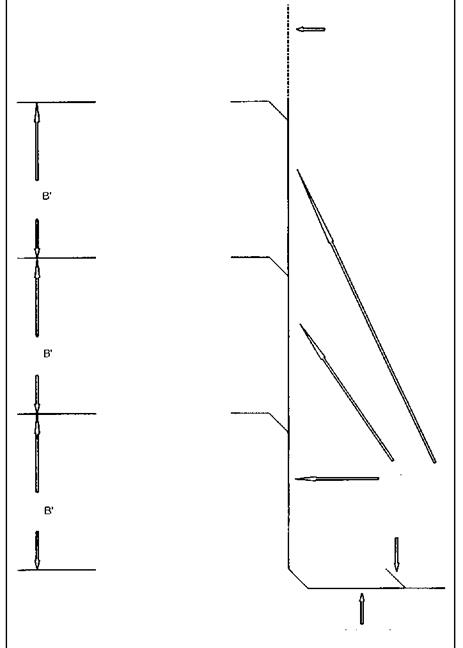
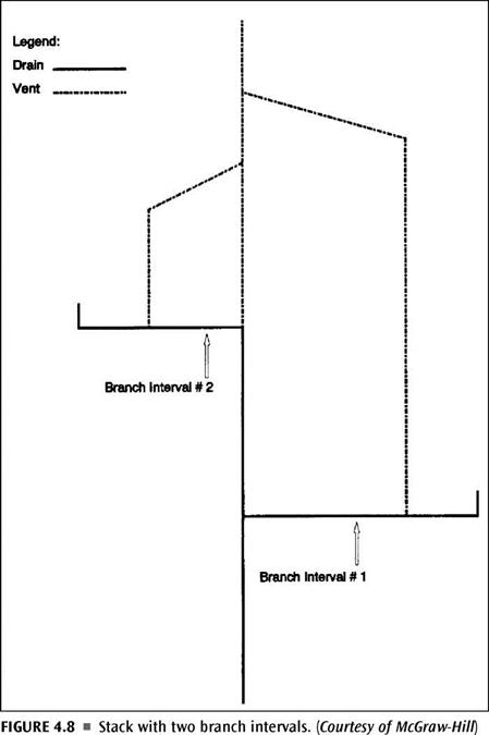
Take a look at Figure 4.7. It is a riser diagram of a branch-interval detail. It is sometimes necessary to break a drainage system down into branch intervals for sizing. If you need to do this, you can refer to this drawing for a clear understanding of where branch intervals break and what they are. Figure 4.8 shows a stack with two branch intervals. To size a system like this, you must apply your sizing techniques to each individual branch and to the stack.
|
|
|
|
|
|
|
|
|
|
|
|
|
|
|
|
|
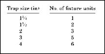
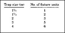
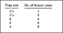
Trap sizing is a simple procedure. All you need is some basic information and a sizing table. If you know your trap size, you can determine the fixture-unit load that is allowable. When you know the number of fixture units that will be placed on a trap, you can decide on a trap size. There’s not much to it. Figures 4.9, 4.10, and 4.11 show limits for fixture units on traps in the three main plumbing codes. If you notice, two of the codes have the same ratings, but one is more liberal than the other two. Remember to use your local code when doing actual sizing.
|
FIGURE 4.9 ■ Zone Two’s fixture – unit requirements on trap sizes. (Courtesy of McGraw-Hill) |
|
FIGURE 4.10 ■ Zone Three’s fixture-unit requirements on trap sizes. (Courtesy of McGraw-Hill) |
|
FIGURE 4.11 ■ Zone One’s fixture – unit requirements on trap sizes. (Courtesy of McGraw-Hill) |
![]()
 |
 |
 |
|
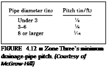
Having the right pitch on a pipe is necessary when complying with a plumbing code. The amount of pitch, or grade, on a pipe can affect its allowable length and fixture-unit load. You can use the tables in Figures 4.12, 4.13, and 4.14 as examples of how a local code might put rules in place for you to follow. The tables are easy to understand and use.
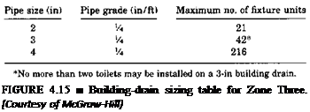
Sizing building drains is simple when you have a sizing table and some basic information. Refer to Figure 4.15 for an example of a sizing table for a building drain. In this example, all pipes are based on a pitch of one-quarter of an inch per foot. A 3-inch pipe can carry up to 42 fixture units, but not more than two toilets. Tables like this one should be available in your local codebook.


Leave a reply