DRILLING HOLES
With the boxes in place, drill holes to run cable from the service panel to the outlet boxes. As noted earlier, a h-in. right-angle drill with a 7/-in. Nail Eater wood-boring bit is the tool of choice.
For individual circuits, in which a cable serves only one appliance, reduce the amount of hole drilling by drilling up through the top plate(s) above the appliance and running cable through the attic till you’re above the service panel. Then drill holes down through the wall plates so you can drop the cable to the panel.
For circuits with many wall outlets, drill through studs 12 in. above the outlet boxes, so the cable can bend gradually toward the boxes. (Avoid sharp bends, which can damage wire insulation.) All holes should be centered in the studs, so that the cable is at least 1’/ in. away from the stud edges; that way drywall screws can’t punc-


ture it. If a cable is closer than 114 in., nail steel nail-protection plates to the studs. Be careful to drill holes at the same height. It’s much easier to pull cable through lined-up holes. A right-angle drill will also ensure that the holes are perpendicular to studs.
Sometimes it’s easier to run cable around an obstruction. For example, it’s possible to run cable through the corner studs if the holes are at the same height and there’s no 2 X blocking at the point where you drill. But if you’re running 12/2 cable or heavier, the cable will be too stiff to pull through the holes at right angles. In this case, drill through the wall plates and go over or under the corner. Likewise, drilling through doubled studs on either side of a door or window opening is a lot of work. So go around.
Finally, drill holes for cable "home runs”— lengths of cable that run from the panel board to the outlet box on each circuit that is closest to the panel.
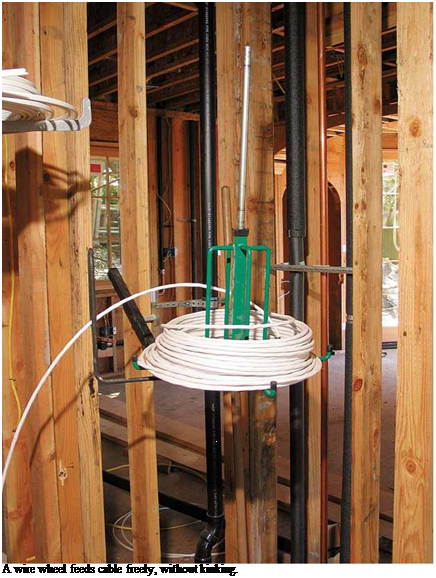
Pulling Romex cable is easier if you reel it off a wire wheel, a rotating cable dispenser that nails to framing and holds 250-ft. coils. Start by placing the wire wheel near each home-run box and pulling off enough cable to extend roughly 1 ft. beyond each box and 4 ft. beyond the knockout where each cable enters the panel. When in doubt, run cable long. For example, wires inside a service panel may need to run 3 ft. to 4 ft. to reach a neutral or ground bus on the opposite side of the panel.
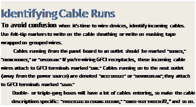
To run cable for individual circuits, again place the wire wheel near each home-run box, but this time pull cable "downstream”—away from the service panel. Many electricians pull cable through holes to the far end of the circuit and then walk back, pulling out additional cable loops that reach at least 8 in. beyond each box. After running cable to all outlet boxes, cut each loop and feed the cable ends into the box openings or knockouts, so the cables stick out about 8 in. Although most duplex receptacle boxes will contain two cables, double – or triple-gang boxes may have four or more.
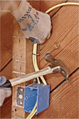
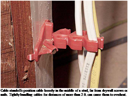
Staple cable within 12 in. of most boxes, and every 4h ft. thereafter. However, if you’re using single-gang plastic boxes without internal cable clamps, staple cable within 8 in. of the boxes. Don’t overdrive the staples; cable should be just snug. When cable runs parallel to joists, staple it to the sides of the joists. When cable runs perpendicular to joists, drill holes through the joists or staple the cable to the underside of each joist. Alternatively, you can nail a 1 X 4 board to the underside of the joists and then staple cable to it.
![]()
 |
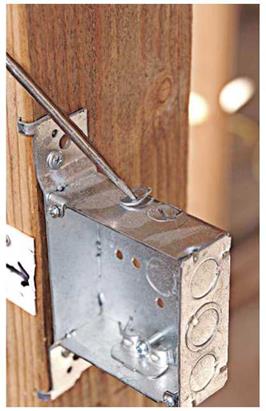 |
All outlet boxes must have clamps that grip cables, except single-gang plastic boxes whose cables must be stapled within 8 in. of the box. (Several Romex connectors are shown in the photo on p. 243.) Clamps secure cable so its connections can’t be yanked—thus preventing strain on connections inside the box. Plastic boxes have tension clamps that allow cable to be pulled in, but not out. When you’re fishing wire and installing cut-in boxes, cable clamps are crucially important because it’s impossible to staple cable hidden by walls.
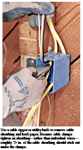
Cable clamps in metal boxes also keep wires from being nicked by burrs created when metal box knockouts are removed. (Use a screwdriver to start knockouts and lineman’s pliers to twist
them free.) To further protect wire insulation, leave a small amount of cable sheathing—roughly h in.—sticking out from under clamps. That is, clamps should tighten down on a remnant of sheathing, not on individual, unsheathed wires. Finally, don’t overtighten clamps, which could damage the wire insulation. And if you remove a knockout mistakenly, use a knockout plug to cover the hole; a knockout plug is a thin cap with barbed sides or spring clips that expand after they clear the edge of the knockout hole. Use one cable per clamp unless the manufacturer allows more.
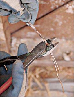
Many electricians use a utility knife to slit and remove plastic sheathing, lightly running the blade tip down the middle of the cable, over the bare ground wire inside. To remove sheathing with less risk of nicking wire insulation, use a cable ripper to slit the sheathing or a cable stripper to remove a sleeve of sheathing. Use a utility knife or side-cut pliers to cut free any slit sheathing or kraft paper still in the box. Tighten the cable clamps; then group like conductors—hot wires to one side, neutrals to the other, grounds in the middle—and cut all wires to the same length, roughly 8 in.
 |
 |
Splicing ground wires. To ensure a continuous ground throughout the system, splice together copper ground wires, using wire nuts or crimps. Ground wires are usually bare copper; if they’re green insulated wires, first strip approximately % in. of insulation off their ends.
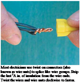
To use wire nuts, first cut the ground wires to the same length, and butt their ends together, along with a 6-in. pigtail that you’ll later connect to the green ground screw of a receptacle. (The grounding pigtail can be bare copper or insulated wire whose ends have been stripped.) Use lineman’s pliers to twist the stripped wire ends clockwise. Trim the ends of the grouped ground wires even; then twist on a wire nut, turning it in a clockwise direction. The threads inside the wire nuts cut into and bind the bare wires. Give a gentle tug to be sure the splice is complete.
To crimp ground wires, gather the wires but don’t twist them. Feed them through a copper sleeve, use a crimping tool to crimp the sleeve tight before snipping all the wires—except one— even with the sleeve. This one long ground wire emerging from the crimped group will connect to the green ground screw of a receptacle. You can use wire nuts to splice (join) ground wires; but crimping them is faster.
If the box is metal, it too must be grounded. Many electricians simply loop the bare-wire grounding pigtail and screw the loop to a green screw in the metal box. The bare-wire pigtail then continues on, to connect to the grounding screw on the receptacle. Or you can add a second pigtail to the ground-wire splice, so that the first screws to the metal box and the second to the receptacle, but that eats up space in the box and slows down the work.
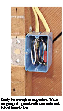
At this point, most local codes require a rough-in inspection. In addition to outlet boxes, inspectors will examine any connections in junction boxes, typically 4-sq.-in. boxes. All electrical connections must be housed in covered boxes, but you must leave junction box covers off till the rough-in inspection is done.
Splicing neutral and hot wires in outlet boxes is essentially the same as splicing ground wires. Once again, a pigtail runs from both the hot and the neutral wire groups and attaches to the appropriate screw terminal on the receptacle. Because neutral and hot wires are always insulated, use wire strippers to strip the insulation off the wire ends.
 Feed the wire into an appropriately sized hole in the tool’s jaws, squeeze the handles, and rock the tool so it cuts the insulation but doesn’t score the conductor. If you are using wire
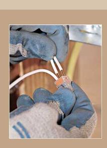 nuts to splice wire groups, strip roughly M in. of insulation from the wire ends; then twist each wire group together, using lineman’s pliers. If you are attaching a pigtail to the receptacle or fixture screws, strip h in. of insulation. Back-wired switches and receptacles have stripping gauges on the back that show how much to strip.
At switches, do not splice hot wires; splice only neutral and ground wire groups. Switches turn fixtures off and on by interrupting the current flowing through hot wires. Therefore, you must attach hot wires to switch terminals, not to each other.


Leave a reply