CONNECTING TO FIXTURES
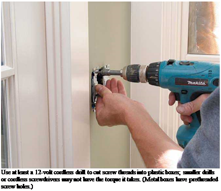
Electrical connections to light or fan fixtures are simple: ground wire pigtail to green screw (if any), hot pigtail to black lead wire or gold screw, and neutral pigtail to white lead wire or silver screw. If fixture lead lines are stranded, cut them a little longer than solid-copper pigtails so that both will seat correctly when they’re spliced with wire nuts. Push-in Wago Wall-Nuts are a good alternative (see "A New Kind of Nut,” on p. 248). Physical connections, such as mounting fixtures
WIRING A RECEPTACLE
|
|
|
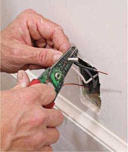
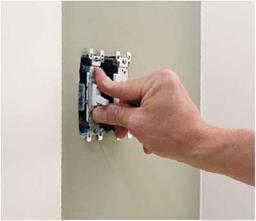
After finish walls are installed and painted, attach the wires to the devices. Start by stripping the wire ends. |
|
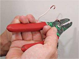
Some wire strippers have a small hole near the handle. Insert a stripped wire, flip your wrist 180 degrees and— voila!—a perfect loop and faster than needle-nose pliers. |
to outlet boxes and attaching outlet boxes to framing, are covered on pp. 260-261.
Wiring fixtures quickly gets complicated when three – or four-way switches control fixtures, as you’ll see shortly. If the fixture is a combo—say, a light and fan—each function is usually controlled by a separate switch. Running three-wire cable (for example, 14/3 with ground) to the fixture enables you to run a separate hot wire to both the fan and the light.
О First, turn off the power. Switches interrupt the flow of current through hot wires only. Neutral wires and ground wires are always continuous, never interrupted. Whether a switch controls a receptacle, fixture, or appliance, hot wires only are attached to switching terminals.
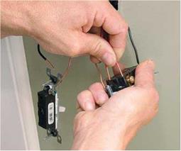
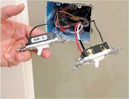
Single-pole switch. A single-pole switch is simple to install. Splice the ground and neutral wire groups as described for receptacles, in the preceding sections. Attach the grounding pigtail to a green grounding screw on the switch, if any. Splice the neutral wires together with a wire nut; they need no pigtail because they don’t attach to switches. Finally, strip h in. of insulation from the ends of the hot wires and attach them to the switch terminals—either by screws or back wiring. It’s customary to install a single-pole switch with the manufacturer’s name at the top, so that the switch toggle will be up when a light is on and down when off.
|
|
||
|
|||
|
|
|||
|
|||
|
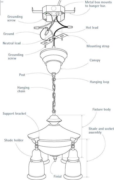
Connecting the incoming wires to fixture leads is standard: hot to hot, neutral to neutral, and splice ground wires. All metal parts should be grounded; if you’re attaching to a metal box, the grounding pigtail to the mounting strap is optional. Note: Fixture bodies and mounting devices vary considerably.
incoming hot wire is spliced to a cable wire running to the switch.
Here, for convenience, we break the rule of using the white wire only as a neutral wire and instead use black tape on each end of the white wire, to show that it is used as a hot wire. At the switch, attach the black wire and the white wire (taped black) to the switch terminals. This allows you to use inexpensive two-wire cable as a switch loop. Thus painting or taping the white wire black is a breach of the rule in letter only, because both wires are technically hot. We have not mixed actual hot and neutral wires.
More complex switches. Switch wiring gets complex when three – and four-way switches require three – or four-wire cable (plus grounds). If you get confused, redraw each configuration, identifying hot wires with an H, neutral wires with an N, and so on. At each splice remind yourself: Neutral wires and ground wires are continuous; switches interrupt hot wires.
If switches or light fixtures have green grounding screws, run a pigtail to them from the
![]()
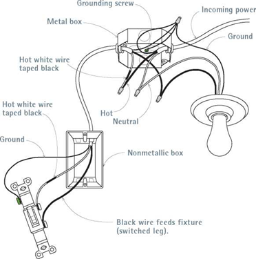 |
 Attach the incoming neutral to a fixture lead; run the hot to a switch at the end of the cable. Use the white wire of a two-wire cable as one of the hot wires attaching to the switch—but tape both ends of the white wire black to show that it’s hot.


|
|
|
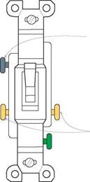
Common (COM) terminal |
|
Traveler wires attach to gold screws. |
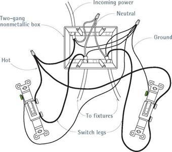
Three-way switches control power from two locations. Each switch has two gold screws and a black screw (common terminal). The hot wire from the source attaches to the common terminal of the first switch. Traveler wires between the switches attach to the gold screws. Finally, a wire runs from the common terminal of the second switch to the hot lead of the fixture.
ground-wire splice (many older fixtures may not have grounding screws). However, if you’re using metal boxes, they must always be grounded: In this case, loop a pigtail from the ground-wire splice to a green screw attached to the metal box.
Conduit and Flexible Metal Cable
The NEC requires that conductors be protected by conduit or flexible metal cable where conductors are exposed, where conductors run through metal studs (and could get nicked), where high moisture could corrode conductors, and so on. Flexible metal cable has factory-installed conductors (wires). But you need to pull conductors through conduit.
Flexible metal cable is commonly used in remodeling, and it satisfies most code requirements. In addition to its use in branch circuits, MC is


Leave a reply