Fixtures, and Switches
О Before working around any electrical device, disconnect the power to it and test with a voltage tester to make sure the power is off.
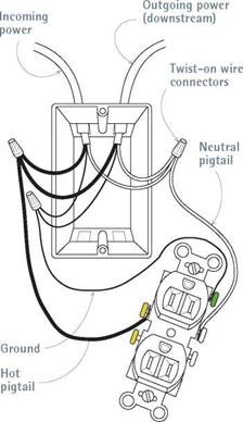
Before beginning this section, read the previous sections on grouping and splicing wire. The following discussion assumes that each wire group (hot, neutral, ground) in the box is spliced together and has a pigtail that attaches to a receptacle terminal. Connecting wires and devices in this manner ensures that there will be continuous current to outlets downstream, even if a receptacle upstream malfunctions or is temporarily removed.
Method one: Using pigtails. First attach the grounding pigtail to the green grounding screw on the receptacle. If the grounding pigtail is insulated, strip ‘A in. of insulation from its end; then use needle-nose pliers or a hole in the wire strip-
A New KIND OF NUT
Splicing with twist-on wire nuts can be problematic. It’s impossible to tell if the wires have come loose as you twist on the nuts; and stranded wire tends to slide down solid wire when you join solid wires to twisted-strand fixture leads. Wago Wall-Nuts™ simplify the task: Strip the wire ends the specified amount, and then push them into nut ports that hold the wires fast. The clear plastic housing allows you to see if the wires are connected, and the ports grasp both stranded and solid wire well.
per handle to loop the end of the pigtail clockwise, as shown in the bottom left photo on p. 25′. Fit the looped wire onto the grounding screw, and then tighten it. (Screws tighten clockwise.) Next strip h in. of insulation from the neutral pigtail, loop it clockwise, and attach it to a silver screw on the receptacle. Finally, strip!2 in. of insulation, then loop and attach the hot pigtail to a gold screw on the opposite side of the receptacle.
When all wires are connected, tighten down any unused screws and gently push the wired receptacle into the outlet box, so the wires fold like an accordion. Make sure that the receptacle
Wiring a Receptacle I in Midcircuit
Note: In the wiring schematics on pp. 248-255, thin, solid lines denote ground wires, white wires denote neutral conductors, and black, red, or slashed wires denote hot conductors-unless otherwise indicated on an illustration.
|
|
By splicing like wire groups and running pigtails (short wires) to the receptacle, this conventional method ensures continuous current downstream.
face is flat to the wall plane, not tilted, and the receptacle is centered in the box. Push the receptacle into the box by hand: If you use the screws to pull the receptacle into the box, you may strip a screw hole in a plastic box. Later, after the walls have been painted, screw a cover plate to the receptacle.
Method two: Feeding through receptacles.
Rather than splicing like wire groups and running pigtails to the receptacles, you can instead attach hot and neutral wires directly to the receptacles. This wiring method—"feeding through receptacles”—is widespread because, on the whole, it is quicker, requires fewer conductors, and results in boxes that are less crowded than those wired with spliced wires and pigtails. It is also acceptable to the NEC.
But feeding wires through receptacles has detractors, who argue that in a circuit so wired, if a receptacle upstream fails or a wire comes loose, receptacles downstream will lose power.
Moreover, there is a voltage drop of about 1 percent per receptacle wired in this manner because receptacles offer more resistance to current flow than wire. If you have 6 or 10 receptacles daisy – chained in this manner, those overheated connections can heat up your electricity bill.
However, in older homes with ungrounded outlets, there’s an upside to feeding through receptacles. If you install a GFCI receptacle on the circuit, the GFCI will protect all receptacles downstream. That is, if there’s a ground-fault at a receptacle downstream, the GFCI will cut power to it and therefore make the entire circuit safer.
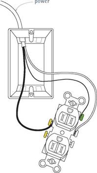
 End of circuit. A receptacle at the end of a circuit has only one cable entering the box and none going beyond it. In this case, it’s acceptable to attach wires directly to the receptacle terminals, without using pigtails. Attach the ground wire to the green ground screw, the neutral wire to a silver screw, the hot wire to a gold screw.

Feeding Wires I through Receptacles
Wiring a Receptacle I at End of a Circuit

|
Attaching hot and neutral wires directly to receptacle terminals is quicker and results in a less crowded box. However, with this wiring method, if the receptacle fails, power can be disrupted to downstream outlets. Note: Ground wires are always spliced to ensure continuity.
Where there are no receptacles downstream, attach wires directly to the device.


![]()
![]()
![]()
![]()

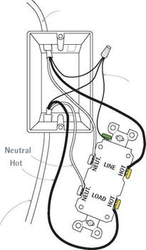
A GFCI receptacle in midcircuit can protect receptacles downstream, if correctly wired. Attach wires from the power source to terminals marked “LINE." Attach wires continuing to receptacles downstream to terminals marked “LOAD." As with any receptacle, attach hot wires to gold screws, neutral wires to silver screws, and grounding wires to the green ground screw. Note: Here, only ground wires are spliced; hot and neutral wires attach directly to screw terminals.
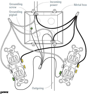
Ganging. By ganging devices you can make the most of limited wall or counter space. Most often, a switch and a receptacle are housed in a single four-square box (4 in. by 4 in.) or in two smaller metal boxes ganged together. Two receptacles will also fit. When in doubt, consult the table "Box Fill Worksheet,” on p. 240, to make sure that the box in question is big enough. When ganging two devices, use two pigtails per wire group so you ensure continuity downstream.


Leave a reply