Cantilever
A cantilever, as in Fig. 2.4, can be thought of as an upside down beam, supported at just one end. It is “upside down” in the sense that its top surface is in tension while its bottom surface is in compression. Note that the unsupported part of the cantilever tends to impart the same kind of upside-down stresses as the supported part. I think of it as being a bit like a first-class lever: the downward pressure of
the overhanging load pivots at the wall (which acts like a fulcrum) and causes an uplifting pressure on the supported portion.

 During my researches, I have found writers (some of them engineers) who say that the over-hanging part should be one-third of the supported apart. Others say 40 percent. Some say 50 percent is the absolute limit. Let us think of these numbers as parameters. Personally, I see no reason in house-
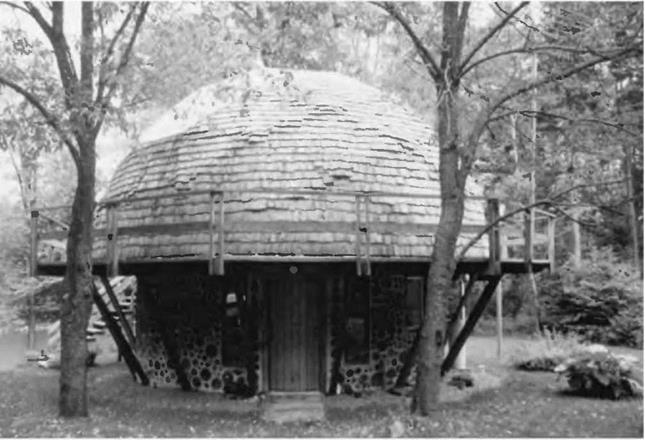
recommendation, and if there is a large load on the cantilever, I’d either Fig. 2.14: The Mushwood Cottage. consult a structural engineer or avoid the cantilever altogether.
At Mushwood, our summer cottage (Fig. 2.14), the second-story 29-foot (8.8- meter) diameter geodesic dome is supported by 16 radial four-by-eight joists, which, in turn, are supported by a 22-foot (6.7-meter) diameter cordwood masonry first story and a large post at the center of the building. The overhang of the dome by itself is 3V2 feet (1 meter) beyond the outside edge of the cordwood wall, and the supported portion of the joist is 11 feet (3.35 meters). Dividing 3.5 by 11 gives 31.8 percent—not too bad at all, it would seem, but really it is not very good, as the dome is applying a concentrated load to the end of the cantilever.
In the case of a concentrated load, an overhang of 25 percent should be thought of as the limit (Clark, 1966, p. 189). However, Jaki and I wanted a three – foot walkway all around the deck, also to be supported by the radial rafters. Snow sliding off the dome accumulates on this deck, a heavy distributed load. If a lot of snow slides off the dome at once, we re looking at an impact load. Adding the 3-foot deck to the зї/2-foot dome overhang, we have a total cantilever of 6V2 feet (1.98 meters). The supported portion of the joist is still 11 feet. The new relationship is 6.5/11 = 59 percent, which exceeds anyone’s rule of cantilever by quite a bit.
We attended to the problem by installing sixteen diagonal supports, which carry the line of thrust from the dome through the diagonals (which are in compression) to the floating slab foundation that supports the cordwood
![]()
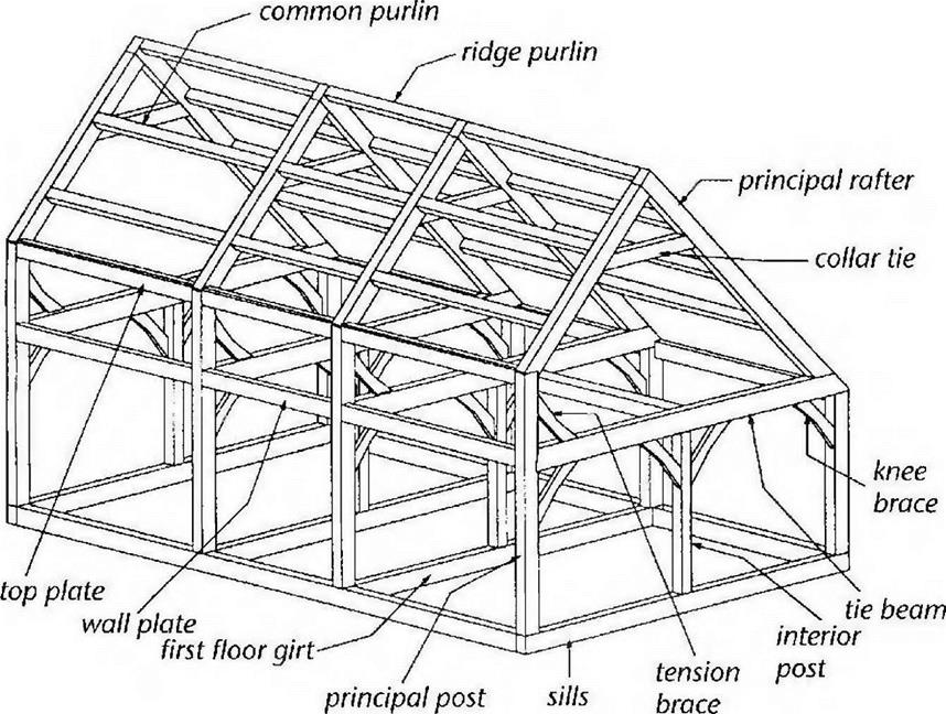
Fig. 2.16: The principal members of this basic bent framing plan are the Posts, Tie Beam, and Rafters. The secondary members are the Interior Posts, Queen Posts, and Collar Tie. The secondary members are necessary only when bent spans exceed the structural limitations of any of the principal members. Braces are required to make this a rigid structural framework. These joints are made with fine crafted joinery, but such a bent could be constructed using mechanical fasteners and then raised into place. The drawing is by Steve Chappell, author of The Timber Framer’s Workshop (Fox Maple Press, 1999), and is used with permission.
|
bent as “a transverse structural frame-work.” Jack Sobon, author of Build a Classic Timber-Framed House (see Bibliography) describes a bent as “an assemblage of timber-frame components that can be put together lying flat and then reared up into position.” He adds that bents are usually cross-frames, but adds that they can also be longitudinal wall frames.
There are no bents at our garage, in the sense of transverse frameworks, although the gable ends could have been built flat on the concrete slab and tilted up into position. The longitudinal sidewall framework could have been built that way, too. In the actual event, posts were simply stood up, individually fastened to the slab as described in Chapters 4 and 5, and the girts heaved into place and fastened together with connectors.
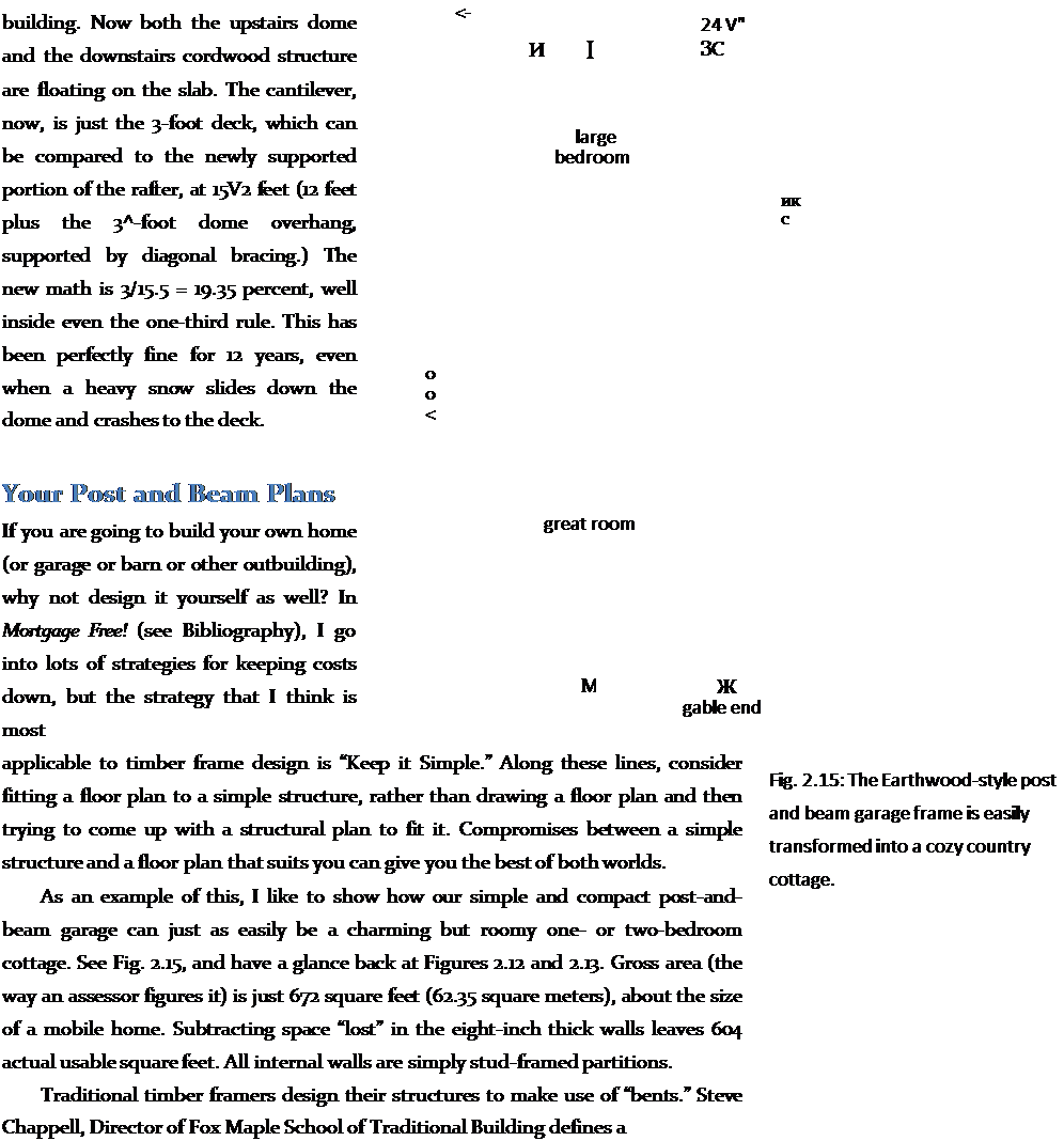
Fig. 2.16 shows a typical bent for a traditional timber frame. The installation of the top portion of such a bent is shown in Fig. 2.17. Four such transverse bents
|
(two internal and one at each gable end) would be the major framework for a structure such as the one shown in Fig. 2.18, except that the upstairs of the frame in Fig. 2.18 is a little different; it is a saltbox design instead of the more common gable roof like Figures 2.16 and 2.17.
 You could put a plank-and-beam roof on the lower frame of a building like our garage, but we chose premade engineered roof trusses to support our shingled roof. The convenience, economy, and strength characteristics of pre-built engineered trusses cannot be over-emphasized, and I will speak more of them in Chapter 4.
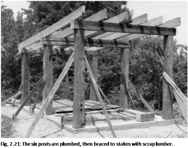
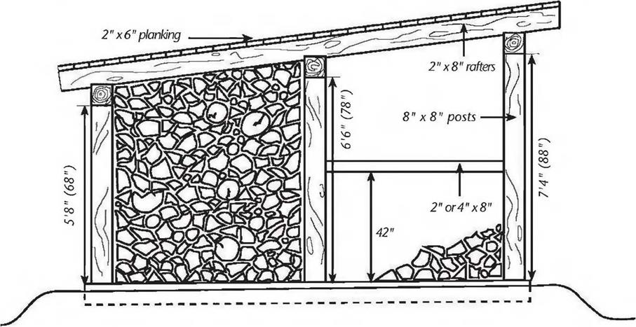
There are as many timber frame plans as there are buildings. At one end of the scale, our little cordwood sauna design consists of just 6 major posts, 3 girders, and 6 long rafters, as per Figures 2.19, 2.20 and 2.21. At the other end of the scale are houses of 3,000 square feet and more.
You can design your own structure based on the design principles in this chapter, keeping in mind the various fastening techniques described in Chapters 4 and 5. Unless you are very confident of your own engineering capabilities — or are using a tried and proven plan — you should have a structural engineer check your plans. This is a lot less expensive than going to an engineer and saying, “Please design me a timber frame for this floor plan and such-and-such a snow load.”
In New York State, any home of 1,500 square feet or greater must carry either an architect’s or an engineer’s stamp to get a building permit. (This takes the onus of responsibility off of the local building inspector.) Ki Light, a neighbor of mine, drew the plans for his post-and-beam house (with straw bale infilling) and took them to a local engineer to see if he could get his plans stamped. Ki and his wife spent a couple of hours with the man, and spoke of things like rafter frequency and span. “It took a while to explain straw bale construction to him,” Ki told me, “but, as we’d be laying up the straw bales within a heavy post-and-beam frame, he
was okay with it.” The meeting cost the Lights $100. They received some good advice, and the engineer stamped their plans. In a couple of days they had their permit.
Another strategy that has worked well for some is to bring your seat-of-the – pants structural drawings to a college engineering class and have the class check and critique the plans… under the guidance of the professor, of course!
Finally, there are two sections in Chapter 4: Building Techniques, which also contribute to an understanding of structure. They are Build Quality, Gravity and Inertia, beginning on page 87, and Roof Systems beginning on page 88. I have put them there because they cover building techniques more than structure. But they are important enough to read now, and then again when you get to Chapter 4.
Now, you will need to know where you are going to get your timbers.


Leave a reply