Category Stone Matrix Asphalt. Theory and Practice

Czech method

2.3.1 General Principles

The Czech method has been employed in the Czech Republic based on the Czech guidelines TP 109.

The distinctive feature of this method is the consideration of the influence of the coarse aggregate content on asphalt mixture properties. Some knowledge of the impact of coarse particle quantity in creating an SMA aggregate structure has been adopted during design. In the Czech method, particles bigger than 4 mm (called

HDK here as designated in Czech method) are regarded as coarse aggregate, making an active part of the aggregate mix.

Stage 7: Selecting an Optimum Content of Binder

After the selection of an optimum aggregate mix, the amount of binder should be selected in such a manner that the desired content of air voids in a compacted SMA

TABLE 7.1

Requirements for a Laboratory-Compacted SMA Binder Mixture Using a Marshall Hammer or superpave Gyratory compactora

property

requirement

Notes

Minimum content of binder,

>6.0

Before adjustment of aggregate density

% (m/m)

Content of air voids in a

>4.0

Usually 3.5-4.0

compacted sample, % (v/v)

Voids in a mineral aggregate VMA, % (v/v)

>17.0

Quantity required at production in an asphalt plant; in fact it should be slightly higher in a laboratory, min. 17.5%-18.0%

VCAMIX

<vcadrc

Appropriate filling volume among coarse particles and stone-to-stone contact are guaranteed

Marshall stability, kN

>6.2

Suggested, not required, quantity applies only to samples compacted with a Marshall hammer

Water resistance, TSR, %

>70

Test after AASHTO T283 (see Chapter 12)

Drain-off at the production

<0.3

Test after AASHTO T305 (see Chapter 8)

temperature in an asphalt plant, % (m/m)

Note: TSR = Tensile Strength Ratio a Based on NAPA SMA Guidelines QIS 122.

sample is available. To achieve this objective, a series of samples with different amounts of binder (usually three points) should be produced, guided by the results achieved in the previous tests with an initially assumed quantity of binder. In reality, 12 samples should be made—four for each point of binder content. Having deter­mined the bulk density and maximum density and calculated the air void content, a target quantity of binder should be selected so that the content of air voids is in the 3.5-4.0% (v/v) range.

The final amount of binder is selected based on test results. The selected SMA composition should be subjected to further testing. The final requirements are dem­onstrated in Table 7.1.

Stage 6: Selecting an Aggregate Mix

An optimum variant should be selected out of the three defined trial design grada­tion curves. The selection criteria of the optimal gradation curve should consist of the smallest amount of coarse aggregate combined with the following two conditions at the same time:

• VCAMIX is lower than VCAdrc or the VCA ratio (VCAmix/VCAdrc) is less than 1.0.

• VMA is higher than 17.0% (v/v) (usually minimum values of 17.5-18.0%).

If the VCAMIX is higher than the VCAdrc, the creation of a skeleton is not guaran­teed. It can be changed by increasing the amount of particles bigger than the BP sieve—that is, increasing the amount of aggregates retained on the BP sieve should increase the VCAdrc. So sometimes additional trial gradations must be analyzed before finding an optimal solution.

Using this method, only one mix is eventually left. The monitoring of the skeleton and aggregate structure is behind us. Now it is time for the binder.

Stage 5: Testing an Aggregate Mix and an Asphalt Mixture

So far, we have carried out a series of tests. Let us sum up all the data at our disposal as follows:

• Air voids in the compacted coarse aggregate VCAdrc

• Initial (or adjusted if needed) content of binder

We have also made a series of compacted SMA samples. Now it is time to determine the following features for them:

• Bulk density of the compacted SMA sample

• Maximum density of the SMA mix

• Content of air voids in the compacted SMA samples (Va)

• Content of VMA

• Content of air voids in the coarse aggregate of the aggregate mix

(VCAMIX)

Among these features, only VCAMIX is a new one. It is vitally important to under­stand the differences between the terms VCAdrc, VMA, and VCAMIX. All of them describe voids in an aggregate mix or one portion of the aggregate mix. Figures 7.9 through 7.11 show their graphic representations. The following is a brief description of the three:

• VCAdrc—content of air voids in the compacted coarse aggregate (coarse aggregate portion of the total aggregate mix, retained on the BP sieve)

image65image66image67vcadrc Volume of air voids in coarse aggregate

Volume of coarse grains

image68,image69,image70
FIGURE 7.9 Definition of VCADrc—the content of air voids in a compacted coarse aggregate.

image71,image72,image73,image74

VCAMIX—content of air voids in the coarse aggregate of a compacted SMA mixture—that is, the volume of everything but the coarse aggregate in the SMA mixture, or the volume of binder, filler, fine aggregate, and air voids)

• VMA—content of air voids in an SMA aggregate mix, equal to the sum of air void volume in a compacted SMA plus the volume of effective binder, excluding filler and fine aggregate

Stage 4: Determining an Initial Content of Binder

The minimum content of binder in an SMA has been fixed at 6.0% (m/m), but a slightly higher quantity of binder in a mixture is advised. This is intended to provide protection from exceeding the lower production limit when producing the SMA.

To begin, an initial trial quantity of binder in mixtures should be adopted (the same for each of the three mixtures). The trial binder quantity should be adjusted depending on the density of the aggregate mixes. The reference density of an aggre­gate mix is typically 2.75 g/cm3; if the density differs, the quantity of binder should be adjusted in accordance with this rule: each change of density by 0.05 g/cm3 cor­responds to an adjustment of binder by 0.1% (m/m). For densities less than 2.75, and for densities greater than 2.75, the adjustments are positive ( + ) or negative (-), respectively.

A series of samples should be made up of 12 specimens of the SMA asphalt mix­ture, four for each SMA trial design gradation. Then nine of the 12 samples will be compacted according to the selected method (three for each SMA design), while the remaining three samples will be used to determine the maximum density according to AASHTO T209.

Samples can be compacted using either the Marshall method or the Superpave gyratory compactor. Compaction parameters are as follows:

• Marshall hammer: 50 blows on each side of a sample 100 mm in diameter

• Superpave gyratory compactor: 100 revolutions[34] on samples 150 mm in diameter

Due to the risk of excessive crushing, higher compaction efforts are not recom­mended. The temperature of compaction samples should be determined using AASHTO T 245, which specifies that the compaction temperature is that at which the binder viscosity equals 280 ± 30 cSt, or that provided by the manufacturer of a modified binder (when applicable).

Dry-Rodded Method

The dry-rodded method has been standardized in AASHTO T 19-00, where its thor­ough description has been included. It is recommended to perform two tests per sample and use the average value. The following gives a short outline of the equip­ment used and the modus operandi.

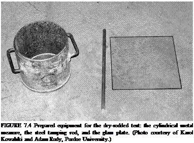
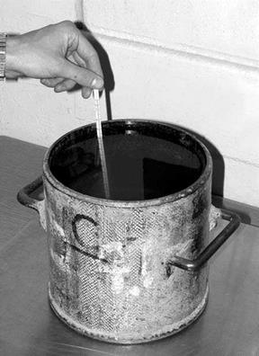
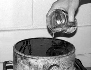
The equipment needed includes a balance, a steel tamping rod (rammer), a cylin­drical metal measure, a shovel, glass calibration plate (Figure 7.4), and grease or thick glycerin. The sample of aggregate is dried in an oven to a constant mass. The sample should be about 125-200% of an amount that fits in the container. The cylin­drical measure is calibrated by determining the volume using water and the glass plate (Figures 7.5 and 7.6); water-density corrective coefficients in relation to the temperature should be taken into account.

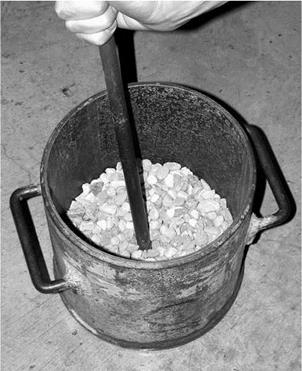
The test is performed as follows: [31] [32]

3.

Подпись: FIGURE 7.4 Prepared equipment for the dry-rodded test: the cylindrical metal measure, the steel tamping rod, and the glass plate. (Photo courtesy of Karol Kowalski and Adam Rudy, Purdue University.)

Having completed tamping the second layer of aggregate, fill the container with aggregate to overflowing and continue tamping down as previously described.

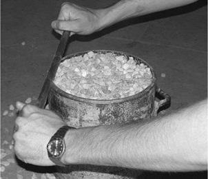
4. Even out the aggregate using your fingers or scrape away any excess aggre­gate with a rod so that protruding coarse particles will compensate for any gaps between them (Figure 7.8).

5. Determine the mass of the compacted aggregate by weighing the measure with aggregate and weighing it empty.

6. Calculations

• Calculate the bulk density of an aggregate according to the formula

G –

V

M = Bulk density of the coarse aggregate, kg/m3 G = Mass of a cylindrical measure and aggregate, kg T = Mass of a cylindrical measure, kg V = Volume of a cylindrical measure, m3 [33]

Dry-Rodded Method

Подпись:

(Gca-y w)-M
G – Y

ca w

-100% (v/v)

image61

FIGURE 7.5 Calibrating the measure—determining the water temperature. (Photo cour­tesy of Karol Kowalski and Adam Rudy, Purdue University.)


image62

FIGURE 7.6 Calibrating the measure—determining the measure volume. (Photo courtesy of Karol Kowalski and Adam Rudy, Purdue University.)


image63

FIGURE 7.7 Tamping down the first layer of a poured aggregate. (Photo courtesy of Karol Kowalski and Adam Rudy, Purdue University.)


image64

FIGURE 7.8 Clearing away the excess aggregate. (Photo courtesy of Karol Kowalski and Adam Rudy, Purdue University.)


M = Bulk density of a coarse aggregate in the dry-rodded condition, kg/m3 Gca = Bulk specific gravity (dry basis) of a coarse aggregate according to AASHTO T85 = GsbD

Yw = Density of water, kg/m3

Stage 3: Determining Air Voids in a Compacted Coarse Aggregate

The Americans have undertaken analyses on the usefulness of various methods of testing for contact between coarse particles. Ultimately, they have settled on the dry – rodded test according to AASHTO T 19-00 (Brown and Haddock, 1997). It has also been standardized as ASTM C29-97.

Let us remember what we are considering now; we are looking for the content of air voids among the compacted coarse particles that make a skeleton. Thus we are screening the coarse aggregate (regarded as the active fraction) of each of three trial aggregate mixes (three design gradation curves of Stage 2) through the boundary sieve (BP sieve) selected in accordance with the NMAS. Furthermore, three such screened samples of the coarse aggregate will be tested according to the dry-rodded method.

What does the dry-rodded method involve? All in all, it consists of compacting the coarse aggregate and determining the air voids among the particles. As a result, dry-rodded testing provides the percentage of air voids in a compacted skeleton of coarse aggregate denoted as VCAdrc. It should be remembered that Volume of coarse Aggregate-Dry Rodded condition (VCAdrc) has been determined for the part of an aggregate mix that is larger than the BP sieve for the size of SMA being designed.

And now the first stage of control in creating the skeleton is behind us.

U. S. METHOD

This method emerged in 1990 after a tour of Europe when some U. S. engineers learned of the benefits of SMA. A series of research efforts started soon after to develop a method of designing SMA. This resulted, among other things, in publica­tions (Brown and Haddock, 1997; Brown and Mallick, 1994) that tried to reach to the heart of the matter of SMA mixtures and suitable methods of designing and testing them.

The essential aspect of designing an SMA aggregate mix using the U. S. method is the introduction of the idea of stone-to-stone contact, or a direct contact among coarse particles. Those grains, called active grains, make a strong mineral matrix and give the SMA its deformation resistance. The method of testing the stone-to-stone contact has also been defined. It is called the dry-rodded test and will be explained later in greater detail. Designing SMA in the United States has been described in different publications (e. g., in NAPA SMA Guidelines QIS 122 and the standards AASHTO M325 and AASHTO R46). The method described in these guidelines will be discussed here. It consists of the following stages: [28]
mix exceed 0.2 g/cm3, the composition of an aggregate mix should be converted from mass into volume, and only such values can be compared with gradation limits (the requirement using AASHTO MP 8-00, currently M325).

7.2.2 Stage 2: Selecting a Gradation Curve

Composing an adequate aggregate mix is the crucial step in the design process. Adequate in this case means meeting the following conditions:

• A design gradation curve lying between the gradation limits

• Suitable contact among coarse particles—that is, the fine aggregate and filler do not interfere with the contact among the largest particles (the stone – to-stone contact is guaranteed)

When the standard method is used, at least three trial aggregate mix composi­tions are designed, with their gradation curves lying close to the upper, middle, and lower gradation boundaries of the allowable ranges of gradation. Obtaining three such curves involves changing ratios between the fine and coarse aggregate contents.

The quantity of filler is generally assumed to be constant, depending on the size of the SMA’s biggest particle. With that in mind, the content of particles smaller than 0.075 mm should amount to approximately 14% (m/m) in the finest SMA 0/4.75 mm, while in coarser SMA mixtures the filler content should be approximately 10% (m/m). With the filler amount essentially fixed, the ratio between coarse and fine particles may be changed to adjust the position of the SMA aggregate mix gradation curve.

U. S. METHOD
image55 image56,image57,image58

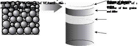
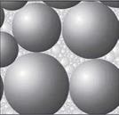
How do we secure contact between the coarse particles? Before discussing this, the aggregate mix should be remembered. The volume division between coarse (skeleton, active) particles and fine ones (filling, passive) is displayed in Figure 7.2. As shown, this division displays a strong particle skeleton made up of appropriate coarse grains. The term coarse aggregates has been intentionally omitted because,

FIGURE 7.2 The volume distribution of the elements in a mineral mix.

after all, the particles are bigger than 2.36* mm; however, these are too small to create a strong skeleton. The boundary sieves for SMA mixtures (called breakpoint [BP] sieves), from which the coarse skeletons start, depend on the following nominal maximum aggregate size (NMAS[29] [30]) of the mixture:

• NMAS > 12.5 mm BP sieve: 4.75 mm

• NMAS = 9.5 mm BP sieve: 2.36 mm

• NMAS = 4.75 mm BP sieve: 1.18 mm

The most common mix is probably SMA 0/12.5 mm with the 4.75 mm BP sieve. According to the method, the skeleton making aggregates are 4.75 mm or larger. So these particles are not simply chippings but a slightly coarser aggregate. A 0/9.5 mm SMA with the 2.36 mm BP sieve has a skeleton made up of typical coarse fraction only (i. e. larger than 2.36 mm).

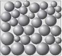
Now let us look again at an SMA 0/12.5 mm. Coarse grains making a skeleton have to be in contact with each other. Next let us consider a compacted layer consist­ing only of coarse aggregate particles. During compaction, the particles will become interlocked tightly so that they will come to rest against each other; and there will be nothing to prevent them from touching. As a result, we have the full, 100% stone – to-stone contact we are aiming at. Now, looking at that compacted layer of coarse aggregate, we can easily see some free space among the coarse particles. If we are able to insert passive (filling) particles into that space, then our aim of preventing the coarse particles from being shoved aside will be achieved. Putting it in a nutshell, particles smaller than 4.75 mm cannot have a higher volume than the remaining air voids in the compacted skeleton part. This way of packing the mix is displayed in Figure 7.3.
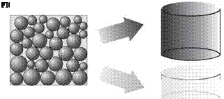
image59 U. S. METHOD

Further steps are self-evident; because all particles bigger than 4.75 mm create the aggregate structure, they have to be examined separately from the aggregate

mix. The next objective will be determining the air voids in a compacted coarse aggregate—namely, the space for filling aggregates.

Volumetric Parameters

The volumetric relationship in an asphalt mixture is shown schematically in Figure 7.1 in German terms. Equations are based on TP A-08 2007 and Hutschenreuther and Woerner (2000).

Symbols in Figure 7.1 include the following:

Hbit = Volume of voids in compacted asphalt samples, % (v/v)

Bv = Binder volume, % (v/v)

Mv = Mineral aggregate volume, % (v/v)

HMbit = Voids in mineral aggregate (VMA), % (v/v)

Obviously, the sum of all the parts should equal 100%.

MV + BV + Hbit = 100%

The way of calculating volume parameters and defining them is outlined here.

Подпись: Hhit

Volumetric Parameters Подпись: Binder volume

Air voids

Aggregate volume

Mv

FIGURE 7.1 Volume relationship in an asphalt mixture according to terminology adopted in Germany. (From Graf, K., Splittmastixasphalt—Anwendung und Bewahrung. Rettenmaier Seminar eSeMA’06. Zakopane [Poland], 2006. With permission.)

Volumetric Parameters

The binder volume in an asphalt mixture

В = Binder content in the mixture, % (m/m)

pA = Bulk density of the asphalt mixture (sample), g/cm3

pB = Binder density at a temperature of 25°C, g/cm3

Volume of mineral aggregate

Подпись: MV =Pa (100 – В)

pR, M

pA = Bulk density of the asphalt mixture (sample), g/cm3 В = Binder content in the mixture, % (m/m) pRM = Density of the aggregate mix, g/cm3

Content of air voids in compacted asphalt mixture

Hbit = PR-bit Pa -100%

PR, bit

pA = Bulk density of the asphalt mixture (in German Raumdichte), g/cm3 pRbit = Maximum density of the asphalt mixture (in German Rohdichte), g/cm3

Air voids in compacted mineral aggregate (the hypothetical voids content)

HM, bit = Hbit + BV

Bv = Binder volume, % (v/v)

Hbit = Air voids in the compacted asphalt mixture, % (v/v) Voids filled with a binder

hfb = -^- • 100%

HM, bit

Bv = Binder volume, % (v/v) HM, bit = VMA, % (v/v)

7.1.3 Comments

• In most cases of designing an SMA, the steps described in Section 7.1.1 are sufficient.

• The void contents in compacted Marshall specimens after the application of various compactive efforts (2 x 50 and 2 x 75 blows [Graf, 2006]) have also been compared. For a designer, a large difference between samples of the same SMA mixture under different compactive efforts is an indicator of too high a compactability under the influence of an excessive effort. However, that practice has not been formalized.

• Some German engineers check the voids in mineral aggregate (HMbit) to find out if it is higher than 18% (v/v), as do their fellow U. S. engineers. However, this practice remains unsanctioned.

Overview of SMA Design Methods

The basic and universal rules of stone matrix asphalt (SMA) design were described in the previous chapter. Chapter 7 provides an overview of SMA design methods devel­oped in various countries. Undoubtedly, there are many of them, so their description could be the subject of a separate book. We will focus here on the most distinctive or the most interesting ones available in the technical literature.

The literature about SMA design methods can be both instructive and creative. You may judge for yourself which method most closely fits your needs or seems to have the most merit.

7.1 GERMAN METHOD

7.1.1 Description of the Method

The German method is based on long-standing experience in the application of repeatable materials and mixes. Such an approach not only makes analyzing cases of successful and unsuccessful SMA much easier but also drawing conclusions and ultimately proposing changes to technical specifications.

It was discussed earlier that the recommended ratios of SMA ingredients (see Table 2.1), combined with precisely determined gradations of each aggregate frac­tion supplied by quarries, enable SMA design in principle almost without the use of boundary gradation curves. Obviously, such gradation curves are being published— the first one for SMA was ZTVbit-StB 84—and then widely applied in practice. The new ZTV Asphalt-StB 07 and TL Asphalt-StB 07 standards have been in use since 1st January 2009.

The following stages may be identified in the German method:

• Design composition of an aggregate mix according to gradation limits

• Determination of a series of binder contents in the mixture

• Preparation of Marshall samples (2 x 50 blows) for each variant of SMA mixture

• Determination of the volumetric parameters of the SMA specimens

• Selection of an optimum variant of the mixture meeting requirements

• Air voids in compacted asphalt samples at 2.5-3.0% (v/v)[27]

• Voids filled with binder

• Draindown testing with Schellenberg’s method

• Wheel-tracking (rutting) test (for selected types of SMA)

The content of the coarse aggregate fraction specified in ZTV Asphalt-StB 07 amounts to 70-80% (m/m) for SMA 8S and SMA 11S but only 60-70% (m/m) for SMA 5N.*