Category Stone Matrix Asphalt. Theory and Practice

Summary of the Method

The determination of air voids based on compacted Marshall samples has been regarded in the Netherlands as the weakest point of the Dutch method of design. According to many engineers, these samples do not reflect the true arrangement of coarse aggregate particles in real pavement. Under real-world conditions, displacement of grains and their close arrangement occur as a result of the high temperature of the pavement and post-compaction; this may be followed by the reduction of air voids among the par­ticles that create the skeleton. Then a significant decrease of air voids in the pavement can result, right up to a complete filling-up with mastic. Subsequently, with a lack of space between the coarse aggregates, they may be shoved aside; the loss of interpar­ticle contact and a bleeding of the mastic onto the surface of a wearing course may occur. Because of that, among other considerations, SMA for heavy traffic is designed with air voids amounting to 5% in the Netherlands, not 3- 4% as in other countries.

Factory or production control adopting the principles depicted in Figure 7.15 appears to be an interesting solution; however, it necessitates the determination of relationships shown there at the design stage, which appears to be a rather time-con­suming procedure. Such activities in a laboratory are reasonable provided that there is a putative guarantee of using aggregates of the same origin over the course of at least one season—that is, an unchanged SMA design will be used for a long period. Then one could afford to carry out such thorough tests. The FPC system requires a new series of tests in case of a change of an aggregate supplier.

The aforementioned method outlined in Section 7.4 describes the state of SMA design in the Netherlands in 2004. A series of research studies were conducted there in 2004-2006, leading to a change in the design procedure. Consequently the pro­cess of design was simplified in 2007. The new cycle of SMA design is as follows: [46]

• Calculate the FRs ratio.

• Calculate an actual SMA void content based on an additional corrective factor (shift factor), which denotes the relationship between the expected and actual SMA void contents.

• Assess an analyzed SMA composition based on the results of the actual air void content, adjust composition if necessary, and redo the calculations.

• Produce extra mixtures of x + 2.5% and x – 2.5% of the coarse aggregate fraction, followed by an assessment of their parameters.

Application of the Method during Production Control

Subsequent to the design of the recipe and its approval, it is time for the pro­duction of an SMA mix. Production control using the Dutch method takes into account the same factors that have been used during SMA design (job mix for­mula [JMF]).

The properties of some elements are naturally changeable; this particularly applies to the aggregate gradation, particle shape, and resistance to crushing.

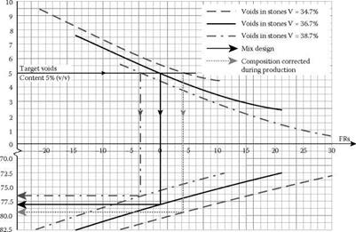
As noted earlier, designing an SMA using the Dutch method is based on optimiz­ing the coarse-aggregate content in order to obtain the selected air void content in compacted samples of the SMA. So if the gradation of the supplied coarse aggregate changes during production of the SMA in an asphalt plant, then the SMA volumet­ric parameters change accordingly. Therefore the factory production control (FPC) should include examining the amount of air voids in the coarse aggregate fraction as used in the SMA design. Each new delivery of coarse aggregates should undergo such tests. The results should be compared with corresponding results of testing the materials used in the SMA design. If the difference in the air void volume is greater than 1.5% (v/v), an adjustment must be made to the design in accordance with the principles put forward in Figure 7.15.

How can we make good use of Figure 7.15? Let us fix the following values of a mix: [44]

image77

FIGURE 7.15 Graph showing the relationship between the contents of coarse aggregate fractions and air voids applied to the adjustments of mixes when producing SMAs. Note: FRs = Filling ratio stone skeleton. (From Voskuilen, J. L.M., Jacobs, M. M.J., and van Bochove, G. G., Proceedings of the 3rd Eurasphalt & Eurobitume Congress Vienna 2004— Paper 326, 1802. With permission.)

Let us assume that the properties of new deliveries of aggregates have altered slightly and are marked by a different content of air voids. To maintain the fixed volumetric relationships in the mix under these circumstances, the content of the coarse-aggre­gate fraction in the SMA design must be changed. Thus we test the new delivery of the coarse-aggregate fraction in a gyratory compactor,* being sure to test not only one single fraction but the entire newly composed material larger than 2 mm. Let us examine two different types of results of this testing:

• Case 1: the content of air voids in the new compacted coarse-aggregate fraction amounts to 34.7% (v/v) (i. e., 2% [v/v] less than in the design).

• Case 2: the content of air voids in the new compacted coarse-aggregate fraction amounts to 38.7% (v/v) (i. e., 2% [v/v] more than in the design).

Whether we deal with the Case 1 or Case 2, the air voids should equal 5% (v/v) of the SMA mix. So let us have a look at Figure 7.15. We can read the instructions on how the content of coarse aggregate fraction in the aggregate mix should be adjusted for the given contents (34.7% and 38.7%) of air voids in the coarse aggregate frac­tions and air voids in SMA (5.0%). Consequently we find: [45]

• Case 1: the content of air voids in the compacted chipping fraction amounts to 34.7% (v/v), so the coarse aggregate content should be increased to approximately 79.5% (m/m).

• Case 2: the content of air voids in the compacted chipping fraction amounts to 38.7% (v/v), so the coarse aggregate content should be decreased to approximately 76.5% (m/m).

Adjustments to the mix make sense. If there are fewer air voids in the coarse aggregate fraction (particles are packed better in a volume unit), it is necessary to increase the coarse aggregate content (“to open” the mix) in order to retain the 5% of air voids in the SMA. If the coarse aggregate mix is more open after compaction than during design, the quantity in the mix should be reduced (it is necessary “to close” the mix). As we can see, this is the same principle that may be applied to adjust two fillers with different contents of air voids according to Rigden.

Preparation of Samples

Preparation of samples for an SMA recipe is conducted according to the Marshall method, with a compaction effort of 2 x 50 blows, or in a gyratory compactor, where the number of rotations are selected in such a manner that the specimen bulk density is similar to results obtained from the Marshall method. While designing SMA with the use of the gyratory compactor, the maximum density of the mix is experimen­tally established.[42] 7.4.3 Design Method

The applied method of SMA design in the Netherlands belongs to the group of volu­metric methods. However, the assumption of a constant amount of binder in a mix makes a significant difference in comparison with other volumetric methods. When any of the final SMA parameters do not comply with the requirements, only the aggregate mix is subject to change. The consecutive stages of design using the Dutch method are discussed next.

The sequence of activities during SMA design is as follows (Jacobs and Voskuilen, 2004; Voskuilen, 2000):

1. Determine the density of materials and execute an aggregate size

analysis.

2. Read a constant binder content (depending on the gradation of the mix)

3. Establish an initial design of the aggregate mix (mix 1).

3.1 Conduct tests of air voids (Vs) in the coarse aggregate fraction (grains greater than or equal to 2 mm) with a gyratory compactor and determine the degree of crushing of the coarse aggregates (analysis of material passing through a 2 mm sieve).

3.2 Adjust the aggregate mix by adding a crushed coarse aggregate fraction to the sand fraction.

3.3 Calculate the volume of mastic for the initially adopted FRs ratio (e. g., -4) using the formula.

V =1 FRs +1 І. V m 100

3.4 Calculate the volumes of the filler and sand in the mix (in the ratio of 65:35 [m/m]) for the previously calculated mastic volume, taking into account the known and constant binder content (e. g., 6.5% [m/m] for SMA 11[43]).

3.5 Calculate the coarse aggregate fraction’s volume in the aggregate mix (the sum of volumes of all constituents should be equal to 100%).

3.6 Convert the estimated volumes of SMA components into mass units.

4. Establish the mass of coarse aggregate fraction in the initial design of an aggregate mix as x% (m/m).

5. Initiate two other variants of the aggregate mix with different contents of the coarse aggregate fraction.

5.1 Mix 2: (x – 2.5%)

5.2 Mix 3: (x + 2.5%)

6. Estimate the sand and filler contents (using the proportion of 65:35 [m/m]) for each of mixes 2 and 3.

7. Prepare SMA Marshall samples (2 x 50 blows) or gyratory compacted sam­ples and determine the air void content in the compacted samples.

8. Determine the relationship between the coarse aggregate fraction content versus the air voids in the SMA.

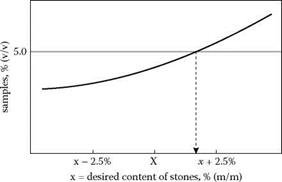
9. Design this coarse aggregate content (directly or through an interpolation of results, see Figure 7.14) so that the content of air voids is in accordance with the requirements presented next.

10. Estimate the FRs ratio for the design mix.

image76

FIGURE 7.14 Example of the design coarse-aggregate fraction content based on the content of voids; x = desired content of stones, % (m/m). (From Voskuilen, J. L.M., Ideas for a volumetric mix design method for Stone Mastic Asphalt. Proceedings of the 6th International Conference Durable and Safe Road Pavements, Kielce [Poland], 2000. With permission.)

The requirements for air voids in compacted SMA 0/11 samples, applied in the Netherlands, are as follows:

• Type 1—for low-volume traffic

• Marshall hammer 2 x 50: 4.0% air voids

• Gyratory compactor: 3.0% air voids

• Type 2—for heavy traffic

• Marshall hammer 2 x 50: 5.0% air voids

• Gyratory compactor: 4.0% air voids

Note: the relationship between air voids obtained from the Marshall method (an impact method) and those obtained from a gyratory compactor should not be interpreted as the difference -1%, because the air void content obtained in samples from the gyratory compactor largely depends on the adopted number of rotations and the angle of rotation of the gyratory compactor. Therefore air void content is not the same in every case.

Practical Guidelines for Design

7.4.2.1 SMA Constituents

Coarse aggregates of 2/6 mm are not permitted in an SMA mixture with a grada­tion of 0/11 mm just to guarantee a gap gradation. The sand fraction has to consist of a minimum of 50% crushed stone, whereas the content of air voids according to Rigden and the bituminous number* should form the basis for selection of the filler. As in many other countries, the amount of stabilizer is based on draindown testing.

The road binder 70/100,* and in special cases modified binder, should be used in SMA. No Reclaimed Asphalt Pavement (RAP) is allowed in SMA in the Netherlands.

7.4.2.2 Designing an Asphalt Mixture

Reading the recommended fixed binder content in SMA from the standard marks the beginning of design. This quantity depends on the SMA gradation; the bigger the maximum aggregate size in a mix, the lower the intended amount of binder. It is necessary to stress again that the accepted amount of binder is a constant value; hence it is not subject to change in the design stage but is to be matched with an aggregate mix.

The amount of binder is fixed prior to establishing the filler content. The con­tent of filler (particles less than 0.063 mm) must fall within the range of 6-10% (m/m). Limestone filler is preferred; since its content of Rigden air voids is known, its behavior in the mixture is somewhat predictable.8

Fixing the amount of the sand fraction is based on the indicated constant ratio of this fraction to the quantity of filler. This ratio amounts to 65:35 (m/m) if the densi­ties are comparable with the reference density.

It has been accepted in the later stages of design that the binder content and the ratio between the filler and sand are fixed and that only the coarse aggregate content is subject to change (design). Of course, the higher the coarse aggregate content, the lower the sand-filler content. As we remember from Chapter 6, for such an assump­tion with a variable quantity of coarse aggregate of the same origin, the VMA will be subject to change.

Finally, the content of the coarse-aggregate fraction should amount to between 72.5 and 82.5% (m/m) according to Dutch regulations, so it is increased by 2.5% (m/m) in comparison with the most frequently used requirements (70-80% [m/m]). This is directly related to the higher requirements for the air voids content in heavy- duty pavements, at the level of 5% (v/v) (in other countries such pavements typically require 3- 4% [v/v]).

Binder and Stabilizer (Drainage Inhibitor)

A constant, fixed binder content, exclusively dependent on the size of the maximum particle, D, in an aggregate mix is the most unusual feature of the Dutch method. When designing SMA, the binder content for a given gradation should be taken from the regulations; for example, an SMA 0/11 for heavy-duty traffic should have a binder content of 6.5% (m/m). The quantity of binder remains unaltered; it is to be matched with a proper gradation of the aggregate mix. In other words, in the Dutch method, for a specified SMA 0/11, one has to design an aggregate mix so that it will contain 6.5% of binder with air voids at the level of 5.0% (v/v)[40] [41].

In many countries in the practice of designing asphalt mixtures it used to be said that the optimal amount of binder has been matched with a given aggregate mix. The Dutch method recommends the reverse. One could say that during the design the optimal aggregate mix had been matched with a given quantity of binder.

Fine Aggregate and Filler

According to concept of van de Ven et al. (2003), an SMA mixture probably has no real stone skeleton immediately after compaction. A real skeleton in SMA is cre­ated during service under the effects of traffic and climatic loading when sand and filler grains between the coarse aggregates (skeleton) may be crushed or moved. Accordingly, at the design stage, the content of fine aggregate and filler must be determined.

Cause-and-effect relationships between the filler and the fine aggregate (crushed sand) have not been determined in a design method. Some Dutch research into this has led to establishing the optimal relationship between those elements. Research on sand-filler mixes and the filling and replacing effects occurring between them have been elaborated on in a Dutch publication (Voskuilen, 2000). This effect is shown in Figure 7.13; its description is as follows:

• The compacted fine aggregate (crushed sand) contains a quantity of air voids.

• As filler (particles smaller than 0.063 mm) is gradually added, it fills the air voids in the sand, and the voids in the sand-filler mix get smaller. This is the filling-stage; the existing skeleton of the mix is made of sand (the shaded area in Figure 7.13);

• The decrease of air voids continues until the voids in the sand are com­pletely filled (reaching the minimum possible); then only air voids in the filler remain;

• The further addition of filler with a simultaneous decrease in the amount of sand causes a gradual increase of air voids in the mix. This is the replace­ment stage; the existing skeleton of the mix is made of filler (the clear area in Figure 7.13), and grains of sand are being shoved aside by filler particles.

We have found the root of the aformentioned effect—after all, it accompanies the supplementing of fine aggregate to coarse grains in SMA—from the gradual
decrease of air voids, through the void’s minimum, up to the gradual skeleton open­ing (as described in Chapter 6 in Section 6.2.3 on binary systems).

Looking at the form of the example in Figure 7.13, which shows the connection between the filler quantity and the content of air voids, we can observe that the rate of decrease of air voids is faster in the filling phase than its increase in the replacement phase. Thus, in the case of necessary adjustments to the content of air voids, a change in the sand fraction content will produce a stronger effect than will altering the filler content (leaving the chipping fraction unchanged) (Voskuilen, 2000).

According to Dutch research (Voskuilen, 2000), the recommended ratio of the quantity of fine aggregate (sand) to the quantity of filler amounts is 65:35 (m/m). If the filler density is about 2.700 g/cm3 and the density of crushed sand is about 2.650 g/cm3, this proportion may be employed without recalculation. Mass proportions should be converted into volume proportions in cases of significant deviations from these density values.

We were aware of air voids among coarse aggregate some time ago; now that we have set the sand-filler ratio, we can determine the total mastic volume in the SMA. The mastic volume is calculated according to the formula (Voskuilen, 2000)

Подпись: Vmimage75
pb pf ps pa

mb = Binder mass, % (m/m)

pb = Binder density, g/cm3

mf = Filler mass, % (m/m)

pf = Filler density, g/cm3

ms = Sand fraction mass, % (m/m)

ps = Sand fraction density, g/cm3

ma = Stabilizer (drainage inhibitor) mass, % (m/m)

pa = Stabilizer (drainage inhibitor) density, g/cm3

The filling ratio stone skeleton (FRs) is used in the Dutch method to determine the theoretical degree of filling of the air voids in the coarse-aggregate skeleton with mastic (i. e., for investigating whether the design mastic volume is an optimal one). FRs is defined with the formula

V – V

FRs = -^—^ -100%
Vs

FRs = Percentage ratio of filling the coarse-aggregate skeleton with mastic, % (v/v)

Vm = Mastic volume, % (v/v)

Vs = Air voids in the compacted coarse-aggregate skeleton, % (v/v)

Air voids in the compacted coarse-aggregate skeleton (Vs) are calculated using the formula

Vs = pg pg -100% pg

pg = Density of the coarse aggregate fraction, g/cm3

pb = Bulk density of the coarse aggregate fraction compacted in a gyratory com­pactor with a lubricating agent, g/cm3

The assessment of FRs ratio is as follows:

FRs < 0 implies that the air voids are not filled with enough mastic.

FRs = 0 implies that the air voids are filled with the mastic.

FRs > 0 implies that the air voids are overfilled with mastic.

For every SMA design, the FRs ratio should not exceed 0. One should remember that this is a theoretical factor and does not take into consideration the enlarging effect of the increasing air voids in the coarse-aggregate skeleton. Due to this, compacted SMA mixtures with air void contents of 4-5% (v/v) can all be marked by FRs = -4 (Jacobs and Voskuilen, 2004). It is easy to see that the content of the coarse-aggregate fraction and the size of air voids in the coarse-aggregate skeleton are dependent on the FRs level.

Coarse-Aggregate Skeleton

The first step, as in the U. S. method (see Section 7.2), is determining the volume of the skeleton of coarse particles and the voids between them available for the remain­ing SMA elements. Determining the volume occupied by the coarse aggregate skel­eton consists of defining its density and testing the coarse aggregate compaction (namely, the amount of air voids remaining among the coarse grains after compact­ing). As we know, the amount of air voids in a compacted coarse aggregate may be determined using the following methods:

• With dry aggregates, using the dry-rodded test after AASHTO T19 as in the U. S. method, or using a gyratory compactor, Marshall hammer, or on a vibrating plate

• Using a special lubricating agent[38] and chosen method of compaction

The substantial difference between the dry-rodded method and other methods is the dry compaction of aggregate used in the U. S. method and the “grease” process used in the others. Explaining this issue logically, air voids determined using the dry – rodded method must be larger because of the higher resistance to the displacement of particles relative to each other, so they will not be arranged as closely as in the grease method. The use of grease will also result in less crushing of the aggregate during compaction. After all, when compacting SMA on a site, the presence of binder in the mixture lubricates it, making the displacement of aggregate particles easier. So it seems that the method using grease, though more problematic in practice, enables us to obtain results closer to reality. Any substance with a viscosity resembling the viscosity of binder at about 150°C may be employed as a lubricating agent or as a grease in the mixture. In the Netherlands, medical oil has been used for that purpose, with 1.5% (m/m) added to the aggregate mixture. The possibility of conducting the whole operation at room temperature, without heating up the oil and aggregate, is a notable advantage of this substance.

The coarse aggregate of an analyzed mixture (a sample of 4 kg) is compacted by being placed in 150 mm diameter specimen mold and undergoing 300 rotations in a gyratory compactor[39] with the external angle of rotation set on 1°. After the density of the coarse-aggregate particles (greater than 2 mm) and the air voids in the compacted aggregate are determined, the aggregate is extracted from the oil and the gradation is measured. Consequently, apart from the result of air voids in compacted coarse aggregates, some additional information is gained on the aggregates’ resistance to crushing. A compactor, when set at 300 rotations, causes overcompaction of the mix­ture and, to some degree, destruction of grains corresponding with the laydown and compaction process and after several years of service.

Another important factor that should be taken into account while analyzing air voids among coarse grains is their crushing and wearing, which occurs at the production stage of a mixture, at its laydown, and during its later service. Crushing of the grains causes the displacement of particles, hence a decrease of air voids in the coarse aggregate skeleton (post-compaction). Coupling this with the knowledge of susceptibility of the aggregate to crushing and wearing that is gained by screening the aggregate after compacting it in the gyratory compac­tor, it is necessary to increase the air voids in the designed SMA to a certain degree (e. g., to 5% instead of 4%). This should guarantee that, even after long­term service under heavy loads, there will be no bleeding of mastic (fat spots) from among the grains of a skeleton. This method of reasoning has been adopted in the Netherlands, where the air void content in compacted laboratory samples for heavy duty traffic has been increased to 5% (v/v) (Jacobs and Voskuilen, 2004; Voskuilen, 2000).

The use of aggregates susceptible to crushing alters the volume relationships in the aggregate mix in the following ways:

• The volume of the coarse particle skeleton decreases (because some of the coarse particles becomes fine particles).

• The volume of fine particles, which are not involved in the coarse skeleton’s performance, increases.

• The content of air voids in the aggregate mixture decreases.

• Consequently the quantity of air voids in the SMA drops, so the risk of overfilling with mastic increases.

Using this method, the effect of increasing air voids in the coarse skeleton has been taken into account. We should remember that air voids have been determined using the method of dry or greased compaction of coarse aggregates. In this test, only the aggregate greater than 2 mm has been used. In a real mixture, coarse grains are coated with mastic, so naturally there are particles of filler or crushed sand among the coarse particles. These particles slightly increase the content of air voids among the coarse aggregates, particularly at the first stage of an SMA’s performance. In the Netherlands the effect of an added increase of air voids among coarse particles has been called the enlarging effect. With the passage of time, the decrease of air voids among coarse aggregates occurs as a result of post-compaction, reorientation of coarse grains, wear, and the movement of fine particles.

General Principles and Some Theory

The principles of designing an aggregate mix and then the content of binder are presented in Figure 7.12. It is an illustration of a telescopic[37] method of creating SMA, which involves inserting consecutive elements into free space (air voids) in a compacted component of a larger size. In other words:

• A volume of fine aggregate is inserted into the air voids in the compacted coarse aggregate skeleton with the effect of increasing the air voids among the coarse aggregates (enlarging effect).

• A volume of filler particles is inserted into the air voids in the compacted fine aggregate.

• A volume of binder is introduced into the air voids in the compacted filler.

• The free space remaining after inserting all these elements produces the content of air voids in a compacted SMA.

Voids Enlarging effect

Filler

Binder + stabilizer

FIGURE 7.12 Placing consecutive elements of SMA in a mixture. (From Voskuilen,

Ideas for a volumetric mix design method for Stone Mastic Asphalt. Proceedings of the 6th International Conference Durable and Safe Road Pavements, Kielce [Poland], 2000. With permission.)

Filling the air voids with the subsequent elements has already been partially dem­onstrated and discussed when explaining the concept of air voids in a filler (see Chapter 3).

Determining the density of all the SMA components is the basis of the design activity because the Dutch method is a volumetric-type method.

DUTCH METHOD

There is a widespread belief among many engineers that SMA, due to its peculiar­ity, should be designed by volume. The volume concept also forms the basis of an experimental method of design applied in the Netherlands.

To put it concisely, we can repeat what has been explained in the previous chap­ters of this book as follows:

• Air voids remain in the stone skeleton after its compaction.

• The volume of mastic, including the fine aggregate, filler, binder, and stabi­lizer (drainage inhibitor), has to be put into that free space.

The following description of this SMA design method includes the guidelines of 2004 and has been prepared based on information from two publications (Jacobs and Voskuilen, 2004; Voskuilen, 2000). This method was revised (simplified) in 2007; a description of the changes made is explained in Section 7.4.5.

Design Method

The SMA design procedure consists of the following stages:

• Selection of the design aggregate mix using an analysis of the impact of the coarse aggregate content on SMA properties

• Determination of the optimum design content of the binder for the selected gradation

Step by step, the design proceeds as follows (for SMA 0/11).

A. Design an aggregate mix

1. Determine the properties of raw materials.

1.1 Gradation of aggregates

1.2 Penetration at 25°C and softening point (R&B) of the binder

1.3 Establishing the compaction temperature for preparing samples (adjusted to the type of binder)

2. Design an aggregate mix gradation according to the required gradation limits; using this method the aggregate mix No. 3 (referred to later as mix 3) is evolving.*

3. (Based on experience)[35] [36]‘ we arbitrarily accept an optimal binder content for mix 3.

4. At this point, mix 3 has an optimal binder content (temporary); next exam­ine the influence of changes to the aggregate mix on SMA features.

5. Design four new variants of an SMA aggregate mix in the following way.

5.1 The binder and filler contents remain unchanged.

5.2 Design four new aggregate mixes.

5.2.1 Mix 1—decrease the content of HDK by -5.0% to -7.0%, and increase the content of fine aggregate by + 5.0 to + 7.0%

5.2.2 Mix 2—decrease the content of HDK by -2.5% to -3.5%, and increase the content of fine aggregate by + 2.5% to + 3.5%

5.2.3 Mix 4—increase the content of HDK by + 2.5% to + 3.5%, and decrease the content of fine aggregate by -2.5% to -3.5%

5.2.4 Mix 5—increase the content of HDK by + 5.0% to + 7.0%, and decrease the content of fine aggregate by -5.0% to -7.0%

– With changes to the content of HDK fraction (> 4 mm), appro­priately decrease or increase the content of the fine fraction (0.09/4 mm); the filler remains unchanged.

– While changing the quantities of HDK and fine fraction, the inter­nal proportions of fractions (e. g., 4/8 and 8/11) should probably be maintained at a constant level.

5.3 Produce four Marshall samples of each mix (1 through 5), each con­taining the same quantity of binder that was adopted for mix 3 as optimal.

5.4 For each mix, determine the following:

5.4.1 Stability according to Marshall

5.4.2 The binder volume

5.4.3 The content of air voids in compacted 2 x 50 samples (M)

5.4.4 The content of air voids in the aggregate mix (Mk)

5.4.5 The voids filled with binder (Sv)

5.5 Draw graphs of relationships between the elements in Step 5.4 and the content of coarse aggregate HDK.

5.6 Analyze the parameters of the mixes (1 through 5) and select the best one, based on:

5.6.1 The analysis of the inflection point at the relationship between the content of air voids and the content of HDK in SMA samples

5.6.2 The designer’s experience

5.7 Based on the results of the analysis of the previous item, select the best gradation curve or determine a new one (i. e., mix 6).

B. Design an optimum binder content

5.8 Based on the results from Step 5.4, the optimum binder content for the selected gradation of 5.7 may be determined by producing a series of Marshall samples again, with a binder content 0.3% (m/m) higher and lower than the amount initially adopted as optimal for mix 3.

5.9 Select an optimal variant of the binder content based on the following:

5.9.1. Stability according to Marshall greater than or equal to 6 kN

5.9.2. Binder volume

Greater than or equal to 14.5% (v/v) for SMA 0/11 Greater than or equal to 15.0% (v/v) for SMA 0/8

5.9.3. The content of air voids in compacted 2 x 50 (M) SMA sam­ples, which should be from 3.0 up to 4.5% (v/v)

5.10 Conduct additional tests for the optimum content of binder in SMA.

5.10.1. Air void content in SMA samples compacted with an excessive effort of 2 x 100, minimum required greater than or equal to 2.5% (v/v)

5.10.2. Resistance for rutting, 10,000 cycles at a temperature of 50°C, required maximum less than 1.6 mm

5.10.3 Test draindown with Schellenberg’s method, required to be less than 0.3% (m/m)

5.10.4 If requirements are satisfied, design is completed.

7.3.3 Summary

To sum up the Czech method, it is worth noting that, despite leaving the simple basic principles of design, it facilitates examining the influence of the coarse fraction on the properties of an SMA mixture. Generally it takes into consideration all of the essential rules and relationships explained in greater detail in Chapter 6.