U. S. METHOD
This method emerged in 1990 after a tour of Europe when some U. S. engineers learned of the benefits of SMA. A series of research efforts started soon after to develop a method of designing SMA. This resulted, among other things, in publications (Brown and Haddock, 1997; Brown and Mallick, 1994) that tried to reach to the heart of the matter of SMA mixtures and suitable methods of designing and testing them.
The essential aspect of designing an SMA aggregate mix using the U. S. method is the introduction of the idea of stone-to-stone contact, or a direct contact among coarse particles. Those grains, called active grains, make a strong mineral matrix and give the SMA its deformation resistance. The method of testing the stone-to-stone contact has also been defined. It is called the dry-rodded test and will be explained later in greater detail. Designing SMA in the United States has been described in different publications (e. g., in NAPA SMA Guidelines QIS 122 and the standards AASHTO M325 and AASHTO R46). The method described in these guidelines will be discussed here. It consists of the following stages: [28]
mix exceed 0.2 g/cm3, the composition of an aggregate mix should be converted from mass into volume, and only such values can be compared with gradation limits (the requirement using AASHTO MP 8-00, currently M325).
7.2.2 Stage 2: Selecting a Gradation Curve
Composing an adequate aggregate mix is the crucial step in the design process. Adequate in this case means meeting the following conditions:
• A design gradation curve lying between the gradation limits
• Suitable contact among coarse particles—that is, the fine aggregate and filler do not interfere with the contact among the largest particles (the stone – to-stone contact is guaranteed)
When the standard method is used, at least three trial aggregate mix compositions are designed, with their gradation curves lying close to the upper, middle, and lower gradation boundaries of the allowable ranges of gradation. Obtaining three such curves involves changing ratios between the fine and coarse aggregate contents.
The quantity of filler is generally assumed to be constant, depending on the size of the SMA’s biggest particle. With that in mind, the content of particles smaller than 0.075 mm should amount to approximately 14% (m/m) in the finest SMA 0/4.75 mm, while in coarser SMA mixtures the filler content should be approximately 10% (m/m). With the filler amount essentially fixed, the ratio between coarse and fine particles may be changed to adjust the position of the SMA aggregate mix gradation curve.
 |
 |
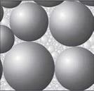
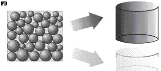
How do we secure contact between the coarse particles? Before discussing this, the aggregate mix should be remembered. The volume division between coarse (skeleton, active) particles and fine ones (filling, passive) is displayed in Figure 7.2. As shown, this division displays a strong particle skeleton made up of appropriate coarse grains. The term coarse aggregates has been intentionally omitted because,
FIGURE 7.2 The volume distribution of the elements in a mineral mix.
after all, the particles are bigger than 2.36* mm; however, these are too small to create a strong skeleton. The boundary sieves for SMA mixtures (called breakpoint [BP] sieves), from which the coarse skeletons start, depend on the following nominal maximum aggregate size (NMAS[29] [30]) of the mixture:
• NMAS > 12.5 mm BP sieve: 4.75 mm
• NMAS = 9.5 mm BP sieve: 2.36 mm
• NMAS = 4.75 mm BP sieve: 1.18 mm
The most common mix is probably SMA 0/12.5 mm with the 4.75 mm BP sieve. According to the method, the skeleton making aggregates are 4.75 mm or larger. So these particles are not simply chippings but a slightly coarser aggregate. A 0/9.5 mm SMA with the 2.36 mm BP sieve has a skeleton made up of typical coarse fraction only (i. e. larger than 2.36 mm).
Now let us look again at an SMA 0/12.5 mm. Coarse grains making a skeleton have to be in contact with each other. Next let us consider a compacted layer consisting only of coarse aggregate particles. During compaction, the particles will become interlocked tightly so that they will come to rest against each other; and there will be nothing to prevent them from touching. As a result, we have the full, 100% stone – to-stone contact we are aiming at. Now, looking at that compacted layer of coarse aggregate, we can easily see some free space among the coarse particles. If we are able to insert passive (filling) particles into that space, then our aim of preventing the coarse particles from being shoved aside will be achieved. Putting it in a nutshell, particles smaller than 4.75 mm cannot have a higher volume than the remaining air voids in the compacted skeleton part. This way of packing the mix is displayed in Figure 7.3.
 |
|
Further steps are self-evident; because all particles bigger than 4.75 mm create the aggregate structure, they have to be examined separately from the aggregate
mix. The next objective will be determining the air voids in a compacted coarse aggregate—namely, the space for filling aggregates.


Leave a reply