Category Stone Matrix Asphalt. Theory and Practice

Original Schellenberg’s Method

A method of mastic draindown testing was published in 1986 by Kurt Schellenberg and Wolfgang von der Weppen (Schellenberg and Weppen, 1986). Their original method, which consisted of warming up a sample of SMA mix placed in a glass beaker, is summarized in Table 8.1.

TABLE 8.1

Parameters of Draindown Testing according to Schellenberg’s Method

Number of samples 1

Test temperature 170°C ± 1°C

Sample weight 1000-1100 g

Test time duration 60 ± 1 minutes

Test procedure 1. Warm-up an empty beaker in an oven at test temperature, take it out and

weigh it, and put it into the oven.

2. Mix SMA components.

3. Remove the beaker from the oven, quickly put a prepared mix into the beaker, and weigh them altogether.

4. Place the beaker with the mix in the oven for 60 ± 1 minutes.

5. Remove the beaker with the mix from the oven and empty the mix by tilting the beaker upside down.

6. Weigh the cooled beaker with remaining mastic to an accuracy of 0.1 g.

7. Calculate the draindown as a ratio of the mass remaining in the beaker to the original SMA mass and express result as a mass percentage.

Source: Based on Schellenberg K. and von der Weppen W., Verfahren zur Bestimmung der Homogenitats-

Stabilitat von Splittmastixasphalt. Bitumen, 1, 1986.

DRAINDOWN TESTING

The draindown effect is the process of the separation of liquid binder or mastic from an SMA mixture that occurs at a high temperature when the binder is still molten.

Both the binder and the mastic can separate. It is common knowledge that SMA mixes are marked by an intentional excess of binder, and the draindown effect is caused by the impossibility of maintaining such an excess of binder on grains of aggregate. That problem is most frequently solved by adding a stabilizer (or drainage inhibitor) to a mix. Its task is to absorb any excess of binder.

Excessive draindown may be caused by several factors (as described in Chapter 4). Binder or mastic draindown from a mix brings about many problems; most of them are described in Chapter 11.

Research on an SMA mix’s susceptibility to binder or mastic segregation has been conducted in virtually all the countries using this type of mix. A short review of the procedures of draindown testing and the regulations for the following methods will be discussed later:

• Using Schellenberg’s method (the original German method)

• Using the European standard EN 12697-18

• Using the U. S. standard AASHTO T 305-97

Preparing Samples with a Granulated Stabilizer

An unexpectedly high draindown may be obtained during laboratory tests in which components, including a granulated stabilizer, are mixed with a small mixer (or manually). This may be caused by the way the granulated stabilizer was prepared before mixing it with aggregates. As we know from Chapter 4, the granules contain a small amount of binder or wax. This coating makes them less sensitive to moisture and makes dosing easier. However, the coating also requires enough shear force and a high enough temperature to release the fibers during mixing.

To avoid trouble with dispersing the granulated fibers, the container with a weighed-out amount of granulated stabilizer should be put in the oven before mixing and warmed up to a temperature at which the binder or wax in the stabilizer clearly softens. This will make distributing the fibers through the mix easier. In an unheated granulated stabilizer, some granules may remain intact; therefore the stabilizer will not work effectively. The effect will be self-evident—an incorrect (high) result of draindown testing.

Be careful when testing stabilizers with which you are unfamiliar. Learn about appropriate mixing temperatures and mixing details, such as whether the stabilizers should be added to the dry aggregate or to the mixture with binder.

Preparing Samples with the Use of a Gyratory Compactor

The use of a gyratory compactor is another popular method worldwide for preparing laboratory samples. This piece of equipment is not new; this method of compacting samples was developed in the late 1930s and early 1940s.[48] Making samples with the use of the gyratory compactor is described in EN 12697-31, ASTM D4013-09, and ASTM D3387-83(2003).

This method of compacting samples consists of kneading a mix with a rotational force. The crucial features of the gyratory compactor are

• Angle of rotation

• Vertical pressure

• Number of gyratory rotations

• Initial (Ninitial)

• Design (Ndesign)

• Maximum (Nmax)

The air void content after an initial number of rotations (usually 9 or 10) are a mea­surement of the compactability of a mix.

There are several types of such instruments, of a dozen or so makes, with more than 3000 examples of them in laboratories. The following are distinct types of these devices:

• Superpave Gyratory Compactor (SGC) is used in the United States for designing mixes using the Superpave method (AASHTO T312 standard) and for designing SMA. Settings according to AASHTO T312 are as follows:

• Internal angle of rotation: 1.16° ± 0.02°

• Vertical pressure: 600 ± 18 kPa

• Rotational speed: 30 ± 0.5 rev/min

• Diameter of sample: 150 mm

• Gyratory Testing Machine (GTM) is the press that was designed and built by the U. S. Army Corps of Engineers.

• Presse de Compactage a cissaillement Giratoire (PCG) is the press that was designed and built by the LCPC[49] in France; its parameters have been adapted to the guidelines of various methods, inter alia Superpave method.

In both the Marshall and gyratory methods of compaction, the important point is fixing suitable design parameters precisely. In the recent past, the number of rota­tions of a gyratory compactor have been established as a parameter corresponding with the number of strokes of the Marshall hammer (to determine density and air void content of a given mix). According to the results of research presented in Brown and Cooley (1999), the number of rotations (Ndesign= 70 or 100) used for an SMA design with an SGC are equivalent of the Marshall hammer compac – tive effort 2 x 50. The number of rotations chosen depends on the resistance to crushing (Los Angeles [LA] index) of the coarse aggregate used; 70 revolutions of an SGC should be assumed when the LA index amounts to 30-45% and 100 revolutions for the LA index less than 30%. In other documents, like NAPA SMA Guidelines QIS 122, the Ndesign = 75 and 100 rotations are used for SMA design with an SGC. The current AASHTO R46 standard corresponds with the NAPA publication (75 and 100 gyrations according to the LA index), values that are used in the United States.

The Australian guidelines NAS AAPA 2004 use a different compactive effort. During SMA design for low – to medium-traffic loading and for heavy – to very heavy-traffic loading, the preferred values are 80 and 120 rotations of the compactor, respectively.

8.1.1 Visual Assessment of Laboratory Samples

A clause in one of the Polish documents on SMA design (ZW-SMA-2001) reads as follows:

After preparing Marshall samples, an additional assessment can be done…. A visual assessment of samples should be carried out: coarse aggregates should be noticeable on the surface of the sample, while voids between them should only be partially filled with mastic…

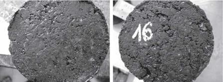
That sounds simple and clear, so let us have a look at a few examples of samples. Figure 8.1 shows an image of a proper SMA sample. There is no excess of mastic, coarse aggregates are visible, and the voids between them are “only partially filled with mastic.” This is how a properly designed and compacted SMA specimen should look.

Figure 8.2 depicts a remarkably different image of SMA samples, though maybe some readers can hardly believe it is still SMA. It really looks like mastic asphalt. There are few, if any, coarse aggregates standing out; voids only partially filled (with mastic) are not easy to find either. Generally, that SMA design could be immediately disqualified, but before rejecting the recipe of Figure 8.2, it is definitely worth giv­ing more thought to the practical reasons of that unsuitable appearance. Mastic is squeezed out, which means there was too much of it in comparison with the free space in the aggregate mix or maybe there were too few air voids in the aggregate mix. Consequently a mistake at the stage of mastic design was made (in which case the mix should be designed once again) or SMA samples were improperly com­pacted (with too great a compaction effort). Maybe the aggregate was too weak and was subsequently crushed during compaction in the mold.

Visual assessment plays only a small role, because human senses may be deceived. After all, we can imagine an SMA sample with a low binder content but compacted with a mighty effort. At that time the sample may look fine—we are under the illu­sion that the mastic-binder content is sufficient. But in the field, a comparable com – pactive effort cannot be applied. As a result, the layer will turn out to be open and

(a) (b)

image78

FIGURE 8.1 The appearance of a Marshall sample of an SMA mix after compaction and removal from the mold: (a) frontal plane and (b) lateral plane. (Photos courtesy of Alicja Glowacka.)

image79

FIGURE 8.2 The appearance of Marshall samples of an SMA mix after compaction and removal from the molds: (a) and (b) are frontal plane views of SMA samples with an excess of mastic. (Photos courtesy by Krzysztof Blazejowski.)

porous. So, despite the good appearance of the lab sample, the mix will not perform successfully in the field. As they say, sometimes looks can be deceiving. On the other hand, the method of visual assessment is sometimes useful, as long as the selected parameters of sample preparation are correct.

Preparing Samples with the Use of the Marshall Hammer

The procedure of preparing samples using the Marshall method is common. It is currently available in EN 12697-30 and ASTM D 6926-04.

The biggest drawback of this method is the incompatibility of laboratory con­ditions and the realism of a construction site. This type of laboratory compaction consists of tamping a mix down with strokes of a predetermined compaction effort defined by the number of impacts on the face of a cylindrical sample.[47] The Marshall method was created several decades ago for designing an optimal content of binder in fine- and medium-graded mixes with continuous grading. Despite progress in technology, the impact method of compaction is still being widely used.

Besides the gap between the lab and the construction site, the most important issue is the energy used for compacting SMA mixtures. Let us have a look at the compaction effort of 2 x 50 (50 strokes on each face of a cylindrical sample) and another one of 2 x 75. Greater compactive efforts—namely, 2 x 75—are typically applied when designing asphalt concrete mixes for courses under heavy traffic. Such considerable compaction efforts may also be used for mixes of continuous grading. Gap-graded mixes with a strong coarse aggregate skeleton, like an SMA, may expe­rience the following two subsequent stages of compaction:

• Compaction of the skeleton until stone-to-stone contact is achieved

• Additional compaction, which may cause the crushing of weaker grains (overcompaction)

The proper compaction of an SMA mix is achieved at the moment when the stone-to-stone contact is reached, which corresponds to a certain amount of com – pactive effort. That is why in most countries (e. g., Germany, the United States) the compactive effort of 2 x 50 has been determined as adequate, regardless of the traf­fic assignment. Though it happens rarely, in some countries the same rules are used for the specification of SMA as for asphalt concrete, specifically 2 x 50 for low – and medium-traffic loading and 2 x 75 for heavy traffic.

In some countries, additional tests of SMA sensitivity to overcompacting are required. In the Czech method (see Chapter 7), typical compaction (2 x 50) is used for design, and an additional test of 2 x 100 strokes is used to indicate the resis­tance of the aggregate mix to overcompaction. It is obvious that after such over­compacting some of the aggregates will be crushed. The requirement for the air void content (more than 2.5% with 2 x 100) in such overcompacted samples could help ensure that even in cases of overcompacting during rolling or when weak aggregates are used, the SMA layer will still have enough void space between the aggregate grains.

Research conducted in many countries (Boratyriski and Krzemihski, 2005; Brown and Haddock, 1997; Perez et al., 2004) into the compaction of SMA has demon­strated clear evidence that an excessive compaction effort put into Marshall samples leads to aggregate crushing and adverse volume changes in the mix.

Analyses and Laboratory Tests

The components of stone matrix asphalt (SMA) and methods of SMA design have been discussed in the previous chapters of this book. In addition to the basic mix design processes, however, there are additional laboratory tests and procedures that are recommended to supplement the mix design work. Some unique tests focus on special properties of SMA mixes that may be encountered from time to time. Therefore it is necessary to undertake a short review of some selected tests. Some guidance is also offered on the interpretation of test results to avoid misunderstand­ings caused by inaccurately defined properties or incorrect test parameters. Such cases are also described in this chapter.

8.1 PREPARING SAMPLES IN A LABORATORY

At present, two methods of preparing samples in a laboratory are commonly applied worldwide: the use of a Marshall hammer or a gyratory compactor. These meth­ods and the problems related to them will be discussed here. Comparisons of other laboratory methods of compacting samples may be found in several publications (Gourdon et al., 2000; Hunter et al., 2004; Renken, 2000).

Method of Successive Iterations

This method, also called the method of iteration, is known chiefly by those who have practiced ready-mix concrete design in a laboratory. It is a laborious procedure because numerous tests need to be conducted (so now it is rarely used). It involves selection of consecutive aggregate fractions so that smaller particles can fit in among bigger ones with no increase in the mix volume (i. e., so that no larger particles are shoved aside by smaller ones).

We start by fixing the proportion of the coarsest aggregate (N1) with a finer frac­tion (N2). Having found such proportions for which we have a minimum of air voids with an unchanged volume of the mix, we mark the acquired mixture as aggregate N1,2. Then we start establishing the proportion of the aggregate N1,2 with the finer aggregate N3, and so on. The process involves making consecutive batches of aggre­gate and determining air voids for each mix. Its comprehensive description has been explained in the publication by Sliwitiski (1999).

Despite the completely different primary purpose of this method, it seems that nothing stands in the way of making use of its principles for determining a suitable gradation of an SMA aggregate mix.

Method of Successive Iterations

Bailey’s Method

The Bailey method was created in the United States in the early 1980s by Robert Bailey of the Illinois Department of Transportation. It enables the selection of an aggregate gradation that guarantees the best interlocking of aggregate particles, a suitable amount of VMA, and proper voids in the final asphalt mix. It was primarily intended for designing continuously graded mixtures with high deformation resis­tance, but it may also be applied to designing SMA gradation.

The method for gradation selection is based on the principle of the packing char­acteristics of aggregates and finally allows designing mixtures with expected aggre­gate interlocking. The complete method is used only for aggregate gradation design, not for full SMA (with binder) recipe design.

Those who are interested in Bailey’s method can refer to the publication by Vavrik et al. (2002), which contains a very detailed description of the consecutive stages of the procedure, calculations, and some examples of design.

Irish Method

In the publication by Brennan et al. (2000) is proposed another method of SMA design developed in Ireland. This method allows for a required discontinuous grada­tion of an asphalt mix between 0.6 mm and 5.0 mm sieves (for SMA 0/14) to create a strong skeleton of coarse grains. The determination of the properties of the coarse aggregate fraction (greater than 2 mm), screened out of the aggregate mix, has been recognized as the key issue, as in other methods. The density of the compacted coarse aggregate fraction is determined by vibration; a sample is tested under low pressure in the mold used during the California Bearing Ratio (CBR) test by placing it on a vibration table commonly used for compacting samples of ready-mix concrete. The sample is compacted to the refusal density with the use of variable values of ampli­tude until the moment particles start crushing (the amount of fine particles smaller than 2 mm is about 1%).

Having already obtained information about the density of the coarse-aggregate fraction and the target content of air voids in the SMA samples, one can use the formulas detailed by Brennan et al. to calculate the necessary content of the coarse – aggregate fraction for the mix to fulfill all determined requirements (e. g., void content).

OTHER METHODS OF DESIGN

7.5.1 Dilation Point Method

The dilation point method, which was devised by the American National Center for Asphalt Technology (NCAT) and then adopted in Australia (Stephenson and Bullen, 2002), serves to determine the maximum content of aggregate less than 4.75 mm (i. e., the passive fraction), which still does not cause the dilation of the coarse aggregate (i. e., the active fraction). The method consists of preparing a series of samples with various contents of fine aggregate. The samples are compacted in a gyratory com­pactor with a constant content of binder and stabilizer. According to the rule, voids among the coarse aggregate are gradually filled with passive particles. This has an impact on the SMA’s particular properties; in the Australian method the resilient modulus is examined. The point at which a skeleton is filled with passive particles is determined through an analysis of the height of samples during compaction in the gyratory compactor. Tests of different contents of fine aggregate at various screen­ings through 4.75, 2.36, 1.18, and 0.6 mm sieves have been conducted.