Category HIGHWAY ENGINEERING HANDBOOK

RIGID PAVEMENT

Rigid pavement can be constructed with contraction joints, expansion joints, dowelled joints, no joints, temperature steel, continuous reinforcing steel, or no steel. Most generally, the construction requirements concerning these options are carefully chosen by the owner or the public entity that will be responsible for future maintenance of the pave­ment. The types of joints and the amount of steel used are chosen in concert as a strategy to control cracking in the concrete pavement. Often, the owner specifies the construction requirements but requires the designer to take care of other details such as intersection jointing details and the like. It is imperative that a designer understand all of these design options and the role each of these plays in concrete pavement performance.

The category of rigid pavements can be further broken down into those with joints and those without. Jointed reinforced concrete pavement (JRCP) and jointed plain con­crete pavement (JPCP) are the two basic types of jointed concrete pavement. Continuously reinforced concrete pavement (CRCP) has no joints. JRCP is designed for maximum joint spacing permitting cracking between joints and requires temperature steel. JPCP is designed for no cracking between joints; thus, joint spacing is mini­mized and temperature steel is eliminated. Historically, many jointed pavements were constructed without dowelled joints. Past performance of undowelled jointed pavements— with the exception of warm, dry climates or low-volume roadways—has been poor. Where there are more than a few trucks per day, dowels should be considered at con­traction joints. However, low-volume roadways that do not carry significant trucks, such as residential streets, may perform satisfactorily without dowelled joints.

PAVEMENT DESIGN AND. REHABILITATION

Aric A. Morse, P. E.

Pavement Design Engineer
Ohio Department of Transportation
Columbus, Ohio

Roger L. Green, P. E.

Pavement Research Engineer
Ohio Department of Transportation
Columbus, Ohio

The movement of people and goods throughout the world is primarily dependent upon a transportation network consisting of roadways. Most, if not all, business economies, personal economies, and public economies are the result of this transportation system. Considering the high initial and annual costs of roadways, and since each roadway serves many users, the only prudent owner of roadways is the public sector. Thus it is the discipline of civil engineering that manages the vast network of roadways.

The surface of these roadways, the pavement, must have sufficient smoothness to allow a reasonable speed of travel, as well as ensure the safety of people and cargo. Additionally, once the pavement is in service, the economies that depend upon it will be financially burdened if the pavement is taken out of service for repair or maintenance. Thus, pavements should be designed to be long lasting with few maintenance needs.

The accomplishment of a successful pavement design depends upon several variables. The practice of pavement design is based on both engineering principles and experience. Pavements were built long before computers, calculators, and even slide rules. Prior to more modern times, pavements were designed by trial-and-error and common sense methods, rather than the more complicated methods being used currently. Even more modern methods require a certain amount of experience and common sense. The most widely used methods today are based on experiments with full-scale, in-service pavements that were built and monitored to failure. Empirical information derived from these road tests is the most common basis for current pavement design methods. More recently, with the ever-expanding power of personal computers, more mathematically based pavement design methods such as finite element analysis and refined elastic layer theory have been introduced. These methods require extensive training to use and are not developed for the inexperienced.

Plan Components

Typical highway construction plans are made up of several individual components. The paragraphs that follow will present a brief discussion of various types of plan sheets that make up a set. Except for major projects, seldom will all of the compo­nents be required in a plan. However, when required, they are usually placed in the order discussed.

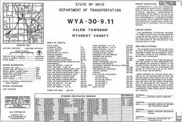
The title sheet is the first in the set and contains a brief description of the project and indication of its length. It displays the title of the project in large, bold letters. It lists the specifications under which the project is to be built, states whether traffic is to be maintained or detoured, gives an index of all plan sheets, lists standard construction drawings and supplemental specifications, and contains the signatures of approval by the appropriate officials. See Fig. 2.74 for an example.

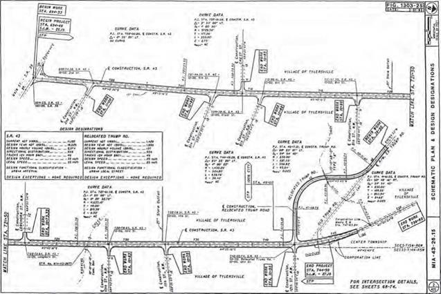
The schematic plan shows the geometric location of proposed roadway segments in relation to existing roadway segments and other major topographic features (rivers, streams, railroads, high-voltage lines, pipelines, etc.). See Fig. 2.75 for an example.

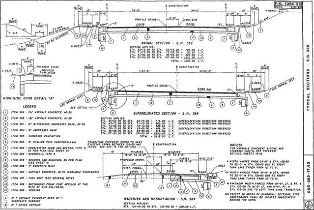
The typical sections sheet is a dimensioned cross-sectional view of how the road­way will appear after construction is completed. These sheets generally show lane widths, shoulder widths, pavement buildup, ditch design, foreslope and backslope rec­ommendations, and tie-ins to existing ground lines. Each section is accompanied by a set or sets of station limits identifying to which portion of the roadway it applies. See Fig. 2.76 for an example.

The general notes sheets contain plan notes to clarify construction items that are not satisfactorily covered by the specifications or plan details. They may be used to modify standard construction drawings.

The maintenance of traffic sheets may include plan view sheets showing location of temporary roads, temporary pavement widening, or detour routes, as well as sheets providing specific notes and instructions regarding sequential construction phases. Details included may be transverse sections showing relationships between the main­tenance roadway and the construction area, as well as placement of channelizing devices and lateral construction limits.

Подпись: ■ mnj bvWTjH ішшти» шигэт rr-Tz гтгтпгтгатт-г- WYA-30-8.11 NONE 3436 STP-49M81
Подпись: 214

Plan Components

Подпись: 215Plan Components

Подпись: 216Plan Components

The general summary sheets contain the itemized list of quantities on which the contractor bid and eventual payment will be based. Any items not listed on these sheets will contain a sheet number reference where they are listed elsewhere in the plans. Each item will usually have a sheet number reference indicating where the item may be found in the plan, or where a subsummary of this information may be found. See Fig. 2.77 for an example.

The calculations sheet provides a record of how quantity pay items were calculated. The sheet provides a way of checking these quantities and also usually indicates by station references where these items are used in the plans.

A storm water pollution prevention plan may be required by some agencies, depending on how much surface area is disturbed by construction. The threshold limit in Ohio is currently 5 acres (20 km2). The purpose of these sheets is to provide infor­mation on how storm water runoff is to be controlled during construction. Details shown will include the location of existing streams, lakes, wetlands, springs, etc., within 250 ft (76 m) of the construction area.

The plan and profile sheets show what an area looks like before and after construction of the project. In addition, they show quantities, dimensions, and other items required to lay out and construct the project. The sheet is normally divided into three areas— plan view, profile, and quantities. See Fig. 2.78 for an example.

The cross sections sheets contain a series of section “slices” of the roadway taken at regular intervals and are used primarily to determine the amount of earthwork and seeding required on the project. They may also be used to locate ditches, show proposed drainage features, design driveways, and establish limits of proposed right-of-way. See Fig. 2.79 for an example.

The miscellaneous details sheets are a section of the plans that serve as a “catch-all” for items that do not fit under other headings. Items that may appear on these sheets include approach slab details with elevations, driveway details, grading plans at inter­sections or interchanges, guiderail details, impact attenuator details, intersection details with elevations, linear grading details, pavement details showing elevations, superelevation tables, and noise barriers.

The drainage details sheets provide details for prefabricated structures and other drainage items that cannot be adequately shown on other sheets. These sheets include culvert details—not only the structure details, but also the grading plan in the vicinity.

Other specialized sheets that may be part of the plan are as follows:

Prefabricated structures Sanitary sewers Water lines

Traffic control (includes proposed signing, striping, and traffic signals)

Lighting

Landscaping

Cast-in-place structures (includes bridges, retaining walls)

Fence plan (refers to right-of-way fencing on limited-access projects)

Right-of-way (listing all affected property owners, parcel numbers, and required right-of-way to be purchased)

Soil profile and foundation investigation

Подпись: 218

Computer-Aided Design and Drafting (CADD)

As an example of the use of CADD files and design software, the Ohio Department of Transportation (ODOT) has stated that this is the preferred method of preparing plans. ODOT has adopted MicroStation and GEOPAK as its standard drafting and design software (Ref. 8). (Note: The preferences mentioned here are those used by ODOT and are cited here only as an example. This is not intended to be an endorsement by the authors. Other agencies use a variety of similar programs.) The standards refer­enced in the ODOT manual have been developed and tested using the software versions listed on the web site www. dot. state. oh. us/cadd/GPKStandards. For a more detailed explanation and background of the use of CADD in ODOT plan development, the reader may view the CADD Manual at www. dot. state. oh. us/cadd/CaddManual.

All highway CADD software programs are based on a two – or three-dimensional coordinate system that assigns coordinates of a specific point to a number or alpha­numeric label. Groups of points make up alignments or property boundaries or road­way centerlines, pavement edges, curbs, sidewalks, etc., in the two-dimensional “plan” view. In the three-dimensional environment, these points have “elevation” values to go along with their x-y plan view coordinates. Likewise, in roadway profiles, similar points make up the vertical profile of a roadway. This also is a two-dimensional

Computer-Aided Design and Drafting (CADD)

FIGURE 2.72 Common transition for concurrent HOV lanes. (From Guide for the Design of High Occupancy Vehicle Facilities, American Association of State Highway and Transportation Officials, Washington, D. C., 2004, with permission)

Computer-Aided Design and Drafting (CADD)

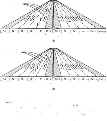
FIGURE 2.73 Typical contraflow HOV lane arrangements. (a) Right curb lane. (b) Left curb lane. (From Guide for the Design of High Occupancy Vehicle Facilities, American Association of State Highway and Transportation Officials, Washington, D. C., 2004, with permission)

display using the centerline of the plan view along with its associated elevation. Although vertical curves consist of a series of closely spaced points in a drawing, they take on the appearance of a “curve” to the viewer. In a cross-section view, the eleva­tion component of the point is shown along with its offset reference to the centerline. The view generated is one in which a “slice” of the roadway is taken as it would look if you took a perpendicular plane to the driver and lifted a section of the road up to see it. In the world of CADD, all these points are three-dimensional and yet have been used, as described above, to generate three different combinations of two-dimensional draw­ings. These two-dimensional drawings make up the majority of the sheets in a set of highway construction plans. The value of CADD is that the points are entered only once, by a described alignment or profile or cross slope in a cross section, and yet have been recalled in numerous applications throughout the plans—whether in developing final cross sections, earthwork calculations, intersection details, drainage designs, etc. CADD software allows the assignment of “names” to various sets of points, such as the centerline of a roadway or the boundary of a property. It also can assign points that are closely associated, if not connected, to a group called a layer or level in the CADD drawing file. One such layer may contain points for a bridge, or even subdivided into layers for bridge deck, bridge abutment, bridge pier, etc. Other layers can be used for hydraulics, lighting, signals, or signs. The assignment of points to layers is limited only by the storage assignment capability of the software and the capacity of the computer memory itself, which far exceeds that required for most projects. The following sec­tions describe the components of a basic set of highway plans, without reference to CADD applications. However, the end product can be completely produced in the CADD environment.

HIGHWAY CONSTRUCTION PLANS

2.14.1 Plan Preparation

The purpose of a set of highway construction plans is to delineate the proposed work with sufficient design details, supplemented with notes, calculations, and summary of quantities, so that it can be clearly and uniformly interpreted by engineers and con­tractors (Ref. 8). Sufficient data must be provided to enable the contractor to make an intelligent bid and to perform the work as intended. Clarity, completeness, and

HIGHWAY CONSTRUCTION PLANS

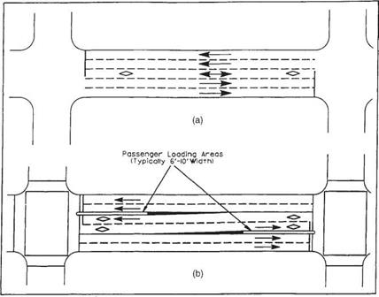
FIGURE 2.70 Examples of median HOV lanes for buses. (a) Reversible lanes for express buses. (b) Two­way lanes for local buses. Conversion: 6 to 10 ft = 1.8 to 3.0 m. (From Guide for the Design of High Occupancy Vehicle Facilities, American Association of State Highway and Transportation Officials, Washington, D. C., 2004, with permission)

conciseness are essential so as to avoid misinterpretation. Unnecessary details should be avoided.

The original tracings serve as a permanent record of the project. They must be prepared on a material acceptable to the agency responsible for maintaining the plans as a record. A currently widely recommended material is the polyester film Mylar with a thickness of 4 mil (3 mil minimum), double – or single – (top side) matted. The surface should not be highly reflective. Only black ink should be used, although grid lines may be colored. Materials that are usually not acceptable include negatives, sepias, vellum, old sheets, dark background, pencil, paste-ons, stick-ons, or bond paper. Original tracings are usually about 22 by 34 in (559 by 864 mm). The designer should prepare the plans keeping in mind that the drawings will most likely be reduced to quarter size (i. e., 11 by 17 in or 280 by 430 mm) prior to distribution.

More and more agencies are switching over to an electronic plan submission. With the overwhelming use of computer-aided design and drafting (CADD) applications, many agencies, large and small, are expressing a preference for plans developed by CADD software. Although paper prints are still necessary as part of the plan develop­ment and construction process, the official filing of Mylar or similar media is being replaced by filing of computer disks that contain design files, including images of plan sheets that can be easily viewed on screen or printed as necessary.

HIGHWAY CONSTRUCTION PLANS

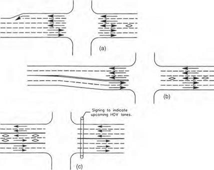
FIGURE 2.71 Typical transitions for median or center lane HOV. (a) With reversible HOV lane and outer transition. (b) With reversible HOV lane and inner transition. (c) With two one-way HOV lanes. (From Guide for the Design of High Occupancy Vehicle Facilities, American Association of State Highway and Transportation Officials, Washington, D. C., 2004, with permission)

Arterial Design Considerations

There are two general categories of HOV lanes for use on surface arterial streets: (1) those which assign exclusive use of designated lanes for HOV use and (2) those which give

Arterial Design Considerations

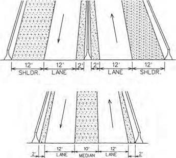
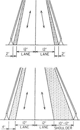
FIGURE 2.63 Cross sections for high-occupancy-vehicle two-way separated lanes on separated roadway. Conversion: 1 ft = 0.305 m. (From Guide for the Design of High Occupancy Vehicle Facilities, American Association of State Highway and Transportation Officials, Washington, D. C., 1992, with permission)

preferential treatment or special privileges to HOVs through traffic control measures. The first category includes concurrent and contraflow reserved lanes, reversible median or center lanes, and streets devoted to HOV use. The second includes such measures as traffic signal preemption systems for buses, and special traffic provisions that allow HOVs to make turns or other maneuvers that are prohibited for other traffic.

Regardless of the type of treatment, the geometric design and traffic control features should accommodate all vehicles that might ultimately use the HOV lane. Since the primary vehicle type using the urban HOV lanes will be buses, special consideration should be given to designing for the vehicle’s dimensions and turning pattern.

Figure 2.70 shows two examples of center lane HOV use. Note the location of passenger loading areas in Fig. 2.70b. The advantage of a center HOV lane over other schemes is that it can be made reversible. Figure 2.71 shows various ways these HOV center lanes are developed.

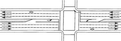
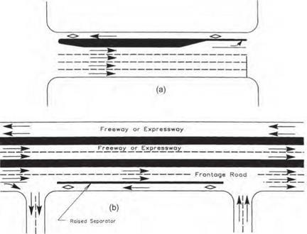
Figure 2.72 shows the more commonly seen concurrent HOV lane developed in the curb lane of an urban street. The advantage of this type of HOV lane is that it is the simplest and least costly to implement. This usually involves only changing signs and pavement markings and coordinating traffic signals.

Contraflow HOV lanes may be used on one-way or two-way streets. On one-way streets, the HOV lane may be either the right or the left lane, while on two-way streets it can be either the right lane or the inside lane adjacent to the median or centerline of the arterial street. Two examples of contraflow lanes are shown in Fig. 2.73.

Arterial Design Considerations

FIGURE 2.64 Connection of HOV terminal mainline lanes to freeway median with flyovers. (From Guide for the Design of High Occupancy Vehicle Facilities, American Association of State Highway and Transportation Officials, Washington, D. C., 2004, with permission)


Подпись: 205Arterial Design Considerations

——— I —

LANE-REDUCTION TRANSITION SIGNING

FIGURE 2.65 Connection of HOV terminal mainline lanes to freeway median with slip ramps. (From Guide for the Design of High Occupancy Vehicle Facilities. American Association of State Highway and Transportation Officials, Washington, D. C., 2004, with permission)

BUSES AND
CARPOOLS
ONLY

6 AM-9 AM V MON-FRI


MOV PAVEMENT MARKING AND SIGNING NOTES


N0 1 LEFT TURN

7-9 AM 4-6 PM

NO

LEFT

TURN

6-9 AW MON-FRI

AUTOS WITH TRAILERS TRUCKS

EXCEPT 3USES AND CARPOOLS

PROHIBITED

MON-FRI

XoR MORE

R44E3


Arterial Design Considerations

R86


10.

11.


Подпись: 206

12.


DETAIL ‘A1

(See Note 9)


X Use appropriate numeral to indicote the number of persons required for a carpool.


Arterial Design ConsiderationsArterial Design Considerations

Arterial Design Considerations

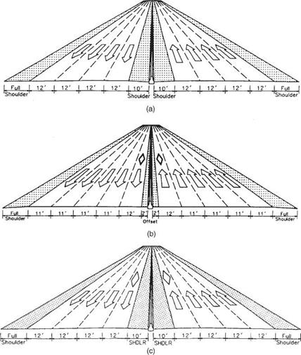
FIGURE 2.67 Contiguous concurrent HOV lanes. (a) Before adding HOV lanes. (b) After adding HOV lanes. (c) Alternative for HOV lanes with shoulders. Conversion: 1 ft = 0.305 m. (From Guide for the Design of High Occupancy Vehicle Facilities, American Association of State Highway and Transportation Officials, Washington, D. C., 2004, with permission)

Arterial Design Considerations

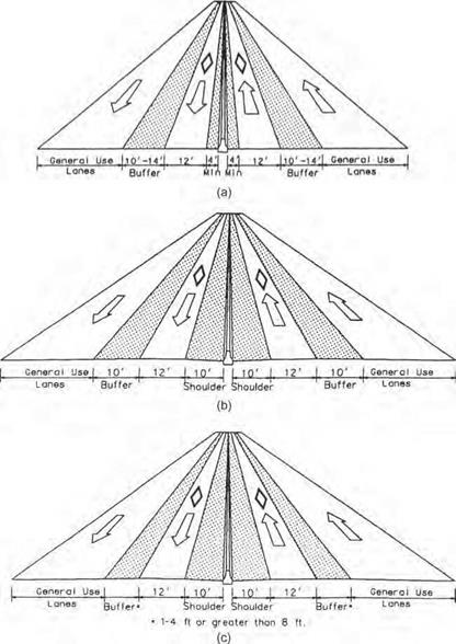
FIGURE 2.68 Examples of concurrent HOV lanes with buffer separation. (a) Without shoulders. (b) With 10-ft-wide buffers. (c) With other buffer widths. Conversion: 1 ft = 0.305 m. (From Guide for the Design of High Occupancy Vehicle Facilities, American Association of State Highway and Transportation Officials, Washington, D. C., 2004, with permission)

Arterial Design Considerations Подпись: Shoulder
Подпись: 10’ Shoulders Desirable
Подпись: Shoulder
Подпись: I 12/ I ■ 2 ^ Full
Подпись: -*4‘ Minimum Shoulders

Arterial Design ConsiderationsFlexible Posts or

Подпись: Shoulder Arterial Design Considerations Arterial Design Considerations Подпись: Shoulder

Movable Barrier

Подпись: the normal flow lanes increasing the contraflow Подпись: an Подпись: width and

Cones or flexible posts in predrilled holes may be moved toward

providing an additional shoulder where a minimum inside shoulder exists. If cones are used they should be deployed with the traffic

Подпись: bufferflow and removed against the traffic flow for safety.

Подпись: lane design is not employed, the posts will be placed along the

lane line in the gaps between the traffic stripes

FIGURE 2.69 Examples of contraflow HOV lanes. (a) With posts on lane line and no buffer. (b) With posts in lane providing buffer. Conversion: 1 ft = 0.305 m. (From Guide for the Design of High Occupancy Vehicle Facilities, American Association of State Highway and Transportation Officials, Washington, D. C., 2004, with permission)

Freeway Design Considerations

There are three types of HOV lane patterns—separated lanes, concurrent flow lanes, and contraflow lanes. Regardless of which pattern is chosen, consideration should be given to traffic operations at interchanges and on-ramps, pedestrian access to on-line stations, the availability of parking areas at or near the stations, and the possible use of HOV lanes during freeway maintenance of traffic operations. Design speeds should generally be the same as for the mainline facility. Recommended lane and shoulder widths can be seen in the next group of referenced figures (Figs. 2.61 through 2.66).

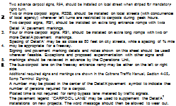
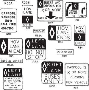
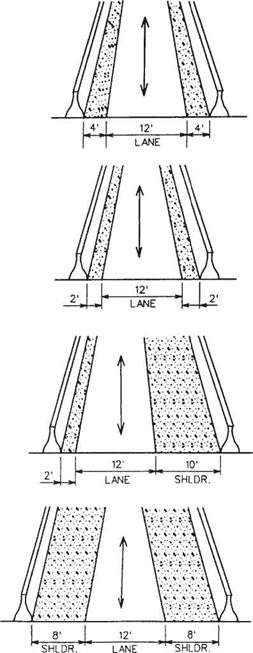
A separated HOV lane may be located in the median or on the outside of the general lanes, or follow an independent alignment. See Figs. 2.61, 2.62, and 2.63 for examples of cross sections. Figures 2.64 and 2.65 show two examples of how separated HOV lanes tie in with the general main lanes of travel. Figure 2.66 shows sample signing and pavement marking used in connection with HOV lanes. Note the diamond symbol that signifies an HOV lane.

Concurrent flow lanes are located adjacent to traffic lanes and are not physically sep­arated from them. Figures 2.67 and 2.68 are examples of typical sections for concurrent HOV lanes.

Freeway Design Considerations

FIGURE 2.61 Cross sections for high-occupancy-vehicle single lane on separated roadway; one-way or reversible. Conversion: 1 ft = 0.305 m. (From Guide for the Design of High Occupancy Vehicle Facilities, American Association of State Highway and Transportation Officials, Washington, D. C., 1992, with permission)

Freeway Design Considerations

FIGURE 2.62 Cross sections for high-occupancy-vehicle double lanes on separated roadway; one-way or reversible. Conversion: 1 ft = 0.305 m. (From Guide for the Design of High Occupancy Vehicle Facilities, American Association of State Highway and Transportation Officials, Washington, D. C., 1992, with permission)

Contraflow lanes provide an exclusive lane for HOVs traveling in the peak direction by removing a lane from service in the off-peak direction. These may be used in areas where traffic volumes in the off-peak directions are such that the level of service is not seriously affected. Some kind of buffer zone or device is strongly recommended for obvious safety considerations. Figure 2.69 provides examples of cross sections for contraflow HOV lanes.

Operational Considerations

Management of HOV facility operations may be accomplished by a range of techno­logical and personnel means. Minimum control may consist of passive signing and delineation. Maximum control may involve sophisticated surveillance, vehicle detection with computer integration, and dynamic, real-time signing or delineation.

A determination of the level of vehicle restriction must be made on the basis of traffic characteristics and how much the HOV lane is used. Restricting use of the HOV lane to vehicles with three or more passengers (3 + ) may give the appearance that the lane is underused. On the other hand, restricting the lane to vehicles with only two or more passengers (2 + ) sometimes results in lane utilization approaching capacity. The best rule of thumb is to start with the 2+ restriction, and go to the 3+ restriction when the level of service of the HOV lane is approaching capacity.

A proper level of enforcement is necessary to ensure that the HOV lane will operate efficiently. Absence of enforcement defeats the purpose of the lane, since single­passenger vehicles will see no need to stay out of the lane. Detection and apprehension of violators, issuance of citations to violators, and effective prosecution of violators are essential.

The hours of operation that an HOV lane is in effect are also an important consider­ation. Twenty-four-hour operation is preferred over peak-hour operation, simply because there is less chance for driver confusion and violations tend to be lower.

HIGH-OCCUPANCY VEHICLE LANES

Another method that is being increasingly used to relieve congestion on urban free­ways is the establishment of high-occupancy vehicle (HOV) lanes. Although the first instances of use in California in the early 1970s met with much public resistance, the idea was revisited and accepted more readily during the mid-1980s and continues to grow in acceptance in highly congested urban traffic areas (Ref. 9). The concept is to provide a separate lane or lanes for high-occupancy vehicles such as buses, carpools, vanpools, and other ride-sharing modes of transportation. This, in turn, provides a positive incentive for the general public to seek out ride-sharing transportation modes, both public and private. The overall goal is to move more people in fewer vehicles.

2.13.1 Planning Considerations

The following transportation system goals can be achieved by proper development and use of HOV lanes (Ref. 3):

• To maximize the person-moving capacity of roadway facilities by providing improved level of service for high-occupancy vehicles, both public and private

• To conserve fuel and to minimize consumption of other resources needed for transportation

• To improve air quality

• To increase overall accessibility while reducing vehicular congestion

Designing and implementing HOV lanes should be limited to those cases where extreme congestion occurs on a regular basis. They should be used in conjunction with other programs that will promote the use of ride-sharing modes, such as park- and-ride lots, park-and-pool lots, and information services to facilitate bus and ride – share needs.

The following guidelines should be used to determine when an HOV lane should be implemented:

• Compatibility with other plans

HOV lanes should be part of an overall transportation plan.

Community support should be obtained for developing HOV lanes.

Intense, recurring congestion should be occurring on the freeway general-purpose lanes.

Peak-period traffic per lane should be approaching capacity (1700 to 2000 vehicles per hour).

During peak periods, average speeds on the freeway main lanes during nonincident conditions should be less than 30 mi/h (48 km/h) over a distance of about 5 mi (8 km) or more.

Compared with using the freeway general-purpose lanes, the HOV lanes should offer a travel time savings of at least 5 to 7 min during the peak hour.

• Coordination with travel patterns that encourage ridesharing

Significant volume of peak-period trips (e. g., more than 6000 home-based work trips during the peak hour) on the freeway should be destined to major activity centers or employment areas in or along the freeway corridor.

At least 65 to 75 percent of peak-period freeway trips to major activity centers should be 5 mi (8 km) or more in length.

Resulting ride-share demand should be sufficient to generate HOV volumes that are high enough to make the facility appear to be adequately utilized; volumes may vary by type and location of facility.

• A design that allows for safe, efficient, and enforceable operation

INTELLIGENT VEHICLE HIGHWAY SYSTEMS

Intelligent vehicle highway systems (IVHS) refers to transportation systems that involve integrated applications of advanced surveillance, communications, computer, display, and control process technologies, both in the vehicle and on the highway (Ref. 5).

In 1991, Congress passed the Intermodal Surface Transportation Efficiency Act (ISTEA), which included an authorization of $660 million to create an IVHS program for the nation. The goals for IVHS were defined as follows: to improve safety, to reduce congestion, to enhance mobility, to minimize environmental impact, to save energy, and to promote economic productivity. Research studies and demonstration projects to accomplish these goals are in progress. Funding has continued under subsequent legislation and experimental “smart highways” are being constructed.

The IVHS program is not limited to urban areas. It should result in benefits for both urban and rural drivers, and for both younger and older drivers. People who use public transportation will also benefit, and others will be persuaded to join them.

A planning process was undertaken following the adoption of the act, which identified 28 user services in six categories (Ref. 5):

Travel and traffic management

• Pretrip travel information

• En route driver information

• Traveler services information

• Route guidance

• Ride matching and reservation

• Incident management

• Travel demand management

• Traffic control

Public transportation management

• En route transit information

• Public transportation management

• Personalized public transit

• Public safety security

Electronic payment

• Electronic payment services

Commercial vehicle operations

• Commercial vehicle electronic clearance

• Automated roadside safety inspection

• Commercial vehicle administrative processes

• Onboard safety monitoring

• Commercial fleet management

• Hazardous material incident notification

Emergency management

• Emergency vehicle management

• Emergency notification and personal security

Advanced vehicle safety systems

• Longitudinal collision avoidance

• Lateral collision avoidance

• Intersection collision avoidance

• Vision enhancement for crash avoidance

• Safety readiness

• Precrash restraint deployment

• Automated vehicle operation

For those services listed under travel and traffic management, the emphasis will be upon providing real-time data to help the driver make the best decisions during a trip or even make last-minute changes in itinerary prior to departure. This category also encourages the use of high-occupancy vehicles and provides traffic control procedures and mechanisms to deal with situations as they occur.

The services under public transportation management will improve the efficiency, safety, and effectiveness of public transportation systems for users and providers alike. Again, the emphasis is on gathering and relaying real-time information to the users of the systems. It provides for automation of operations, planning, and manage­ment functions of public systems. It will also be able to monitor the environment in public station areas, including bus stops and parking lots, to generate alarms when necessary and increase public safety.

Electronic payment services will promote intermodal travel by providing a common electronic payment medium for all transportation modes and functions, including tolls, transit fares, and parking. One “smart card” could be used for several different modes of transportation.

Under commercial vehicle operations, trucks and buses equipped with transponders could have their safety status, credentials, and weight checked at mainline speeds. Vehicles passing the check would not have to pull over into the inspection/weigh facility. Automated safety inspections would allow “real-time” access at the roadside to the performance record of carriers, vehicles, and drivers. By using sensors and diagnostic equipment, vehicle systems and even driver alertness can be checked without stopping the vehicle.

Under emergency management, the capabilities of fleet management, route guidance, and signal priority can be used for emergency vehicles. Police, fire, and medical units can be directed over the most expeditious route to an incident site using real-time information. Driver and personal security systems will allow the user to initiate distress signals for incidents like mechanical breakdowns. Automatic collision notification would send information regarding location, nature, and severity of the incident to emergency personnel.

Concerning those services under advanced vehicle safety systems, a series of collision avoidance systems would be developed. For potential longitudinal, lateral, and intersection collisions, the systems would be able to sense impending trouble, warn the driver, and temporarily control the vehicle. On attempted lane changes, the driver’s blind spot would be monitored, and the vehicle prevented from making the switch if a vehicle was present. Another possibility is vision enhancement for the driver, in which the roadway and roadside are continuously scanned for potential hazards and the driver is made aware of situations when necessary. In-vehicle equipment can be used to monitor the driver’s condition and issue appropriate warnings. In employing precrash restraint deployment, the velocity, mass, and direction of the vehicles and objects involved in a potential crash are identified and the number, location, and physical characteristics of occupants are determined. This information in turn is used to trigger responses, such as tightening of lap-shoulder belts, arming and deploying air bags at optimal pressure, and deploying roll bars. Another program being investigated is automated vehicle operation. This would ultimately provide an accident-free environment on the roadway. Drivers would be able to buy a vehicle already equipped to drive under these conditions, or purchase instru­mentation and have it installed on an existing vehicle.