Plan Components
Typical highway construction plans are made up of several individual components. The paragraphs that follow will present a brief discussion of various types of plan sheets that make up a set. Except for major projects, seldom will all of the components be required in a plan. However, when required, they are usually placed in the order discussed.
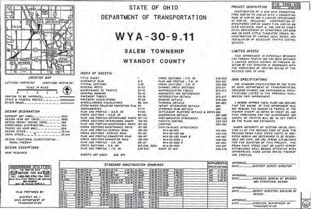
The title sheet is the first in the set and contains a brief description of the project and indication of its length. It displays the title of the project in large, bold letters. It lists the specifications under which the project is to be built, states whether traffic is to be maintained or detoured, gives an index of all plan sheets, lists standard construction drawings and supplemental specifications, and contains the signatures of approval by the appropriate officials. See Fig. 2.74 for an example.
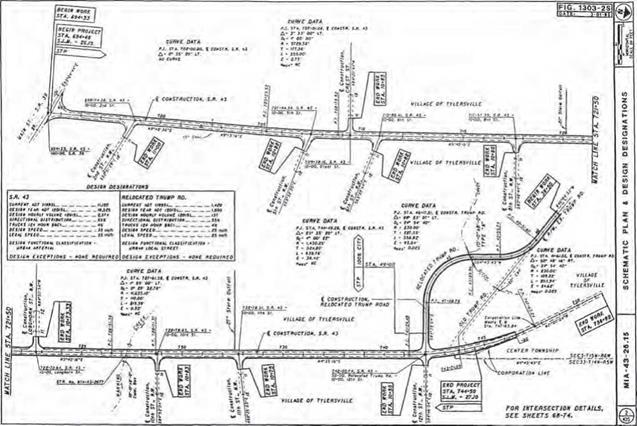
The schematic plan shows the geometric location of proposed roadway segments in relation to existing roadway segments and other major topographic features (rivers, streams, railroads, high-voltage lines, pipelines, etc.). See Fig. 2.75 for an example.
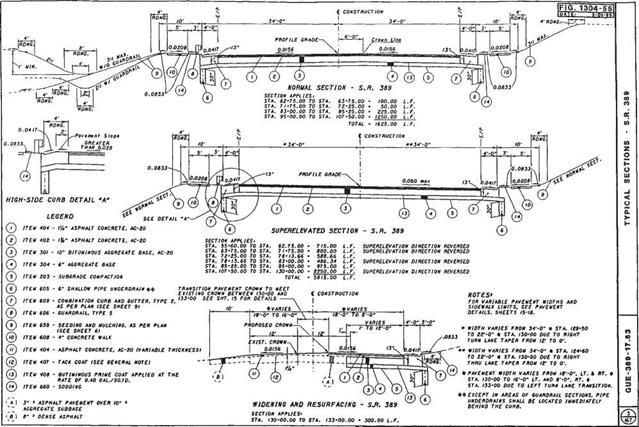
The typical sections sheet is a dimensioned cross-sectional view of how the roadway will appear after construction is completed. These sheets generally show lane widths, shoulder widths, pavement buildup, ditch design, foreslope and backslope recommendations, and tie-ins to existing ground lines. Each section is accompanied by a set or sets of station limits identifying to which portion of the roadway it applies. See Fig. 2.76 for an example.
The general notes sheets contain plan notes to clarify construction items that are not satisfactorily covered by the specifications or plan details. They may be used to modify standard construction drawings.
The maintenance of traffic sheets may include plan view sheets showing location of temporary roads, temporary pavement widening, or detour routes, as well as sheets providing specific notes and instructions regarding sequential construction phases. Details included may be transverse sections showing relationships between the maintenance roadway and the construction area, as well as placement of channelizing devices and lateral construction limits.

![]()

![]()

The general summary sheets contain the itemized list of quantities on which the contractor bid and eventual payment will be based. Any items not listed on these sheets will contain a sheet number reference where they are listed elsewhere in the plans. Each item will usually have a sheet number reference indicating where the item may be found in the plan, or where a subsummary of this information may be found. See Fig. 2.77 for an example.
The calculations sheet provides a record of how quantity pay items were calculated. The sheet provides a way of checking these quantities and also usually indicates by station references where these items are used in the plans.
A storm water pollution prevention plan may be required by some agencies, depending on how much surface area is disturbed by construction. The threshold limit in Ohio is currently 5 acres (20 km2). The purpose of these sheets is to provide information on how storm water runoff is to be controlled during construction. Details shown will include the location of existing streams, lakes, wetlands, springs, etc., within 250 ft (76 m) of the construction area.
The plan and profile sheets show what an area looks like before and after construction of the project. In addition, they show quantities, dimensions, and other items required to lay out and construct the project. The sheet is normally divided into three areas— plan view, profile, and quantities. See Fig. 2.78 for an example.
The cross sections sheets contain a series of section “slices” of the roadway taken at regular intervals and are used primarily to determine the amount of earthwork and seeding required on the project. They may also be used to locate ditches, show proposed drainage features, design driveways, and establish limits of proposed right-of-way. See Fig. 2.79 for an example.
The miscellaneous details sheets are a section of the plans that serve as a “catch-all” for items that do not fit under other headings. Items that may appear on these sheets include approach slab details with elevations, driveway details, grading plans at intersections or interchanges, guiderail details, impact attenuator details, intersection details with elevations, linear grading details, pavement details showing elevations, superelevation tables, and noise barriers.
The drainage details sheets provide details for prefabricated structures and other drainage items that cannot be adequately shown on other sheets. These sheets include culvert details—not only the structure details, but also the grading plan in the vicinity.
Other specialized sheets that may be part of the plan are as follows:
Prefabricated structures Sanitary sewers Water lines
Traffic control (includes proposed signing, striping, and traffic signals)
Lighting
Landscaping
Cast-in-place structures (includes bridges, retaining walls)
Fence plan (refers to right-of-way fencing on limited-access projects)
Right-of-way (listing all affected property owners, parcel numbers, and required right-of-way to be purchased)
Soil profile and foundation investigation
![]()


Leave a reply