Arterial Design Considerations
There are two general categories of HOV lanes for use on surface arterial streets: (1) those which assign exclusive use of designated lanes for HOV use and (2) those which give
|
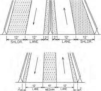
FIGURE 2.63 Cross sections for high-occupancy-vehicle two-way separated lanes on separated roadway. Conversion: 1 ft = 0.305 m. (From Guide for the Design of High Occupancy Vehicle Facilities, American Association of State Highway and Transportation Officials, Washington, D. C., 1992, with permission) |
preferential treatment or special privileges to HOVs through traffic control measures. The first category includes concurrent and contraflow reserved lanes, reversible median or center lanes, and streets devoted to HOV use. The second includes such measures as traffic signal preemption systems for buses, and special traffic provisions that allow HOVs to make turns or other maneuvers that are prohibited for other traffic.
Regardless of the type of treatment, the geometric design and traffic control features should accommodate all vehicles that might ultimately use the HOV lane. Since the primary vehicle type using the urban HOV lanes will be buses, special consideration should be given to designing for the vehicle’s dimensions and turning pattern.
Figure 2.70 shows two examples of center lane HOV use. Note the location of passenger loading areas in Fig. 2.70b. The advantage of a center HOV lane over other schemes is that it can be made reversible. Figure 2.71 shows various ways these HOV center lanes are developed.
Figure 2.72 shows the more commonly seen concurrent HOV lane developed in the curb lane of an urban street. The advantage of this type of HOV lane is that it is the simplest and least costly to implement. This usually involves only changing signs and pavement markings and coordinating traffic signals.
Contraflow HOV lanes may be used on one-way or two-way streets. On one-way streets, the HOV lane may be either the right or the left lane, while on two-way streets it can be either the right lane or the inside lane adjacent to the median or centerline of the arterial street. Two examples of contraflow lanes are shown in Fig. 2.73.
|
![]()

——— I —
LANE-REDUCTION TRANSITION SIGNING
FIGURE 2.65 Connection of HOV terminal mainline lanes to freeway median with slip ramps. (From Guide for the Design of High Occupancy Vehicle Facilities. American Association of State Highway and Transportation Officials, Washington, D. C., 2004, with permission)
|
||||||||||||||
|
||||||||||||||
|
||||||||||||||
 |
||||||||||||||
|
||||||||||||||
|
||||||||||||||
|
||||||||||||||
|
||||||||||||||
|

|
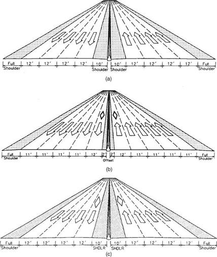
FIGURE 2.67 Contiguous concurrent HOV lanes. (a) Before adding HOV lanes. (b) After adding HOV lanes. (c) Alternative for HOV lanes with shoulders. Conversion: 1 ft = 0.305 m. (From Guide for the Design of High Occupancy Vehicle Facilities, American Association of State Highway and Transportation Officials, Washington, D. C., 2004, with permission) |
|
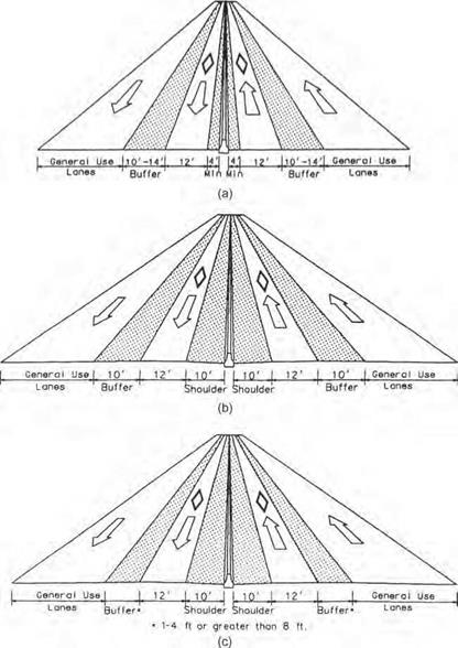
FIGURE 2.68 Examples of concurrent HOV lanes with buffer separation. (a) Without shoulders. (b) With 10-ft-wide buffers. (c) With other buffer widths. Conversion: 1 ft = 0.305 m. (From Guide for the Design of High Occupancy Vehicle Facilities, American Association of State Highway and Transportation Officials, Washington, D. C., 2004, with permission) |
 Flexible Posts or
Movable Barrier
Cones or flexible posts in predrilled holes may be moved toward
providing an additional shoulder where a minimum inside shoulder exists. If cones are used they should be deployed with the traffic
![]() flow and removed against the traffic flow for safety.
flow and removed against the traffic flow for safety.
lane line in the gaps between the traffic stripes
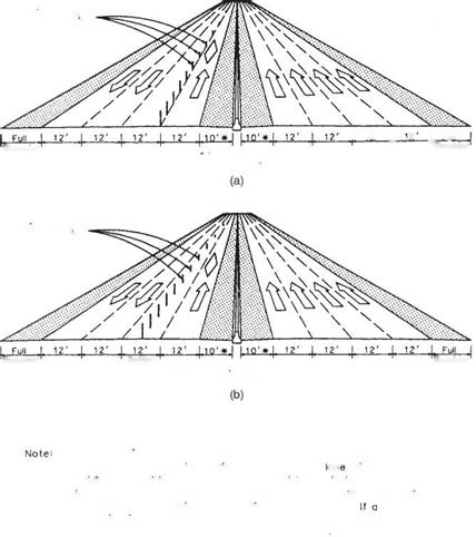
FIGURE 2.69 Examples of contraflow HOV lanes. (a) With posts on lane line and no buffer. (b) With posts in lane providing buffer. Conversion: 1 ft = 0.305 m. (From Guide for the Design of High Occupancy Vehicle Facilities, American Association of State Highway and Transportation Officials, Washington, D. C., 2004, with permission)



Leave a reply