Blog Archives

I-JOIST CUTTING GUIDE
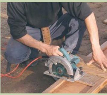
I-JOIST CUTTING GUIDEI-joists are awkward to cut because the top and bottom chords are wider than the web. To overcome this difficulty, make a simple jig with 3/4-in.-thick plywood. Cut a rectangular piece of plywood to fit between the chords and serve as the base of the jig. Screw a longer piece to the first piece, positioning it to guide a 90-degree cut. The edge of the top piece guides the base of the circular saw, as shown in the photo at right. Lay the guide on the I-joist, set the saw on it, and make a square cut. It’s that simple.

Cut I-joists with a guide. Scrap sheathing that is nailed or screwed together creates an effective guide for cutting I-joists. [Photo by Roe A. Osborn, courtesy Fine Homebuilding magazine © The Taunton Press, Inc.]

Подпись: Install the rim joists. The outside face of the rim joist (also called a band joist) must be flush with the outside edge of the sill. Toenail each joist to the sill, spacing 16d nails 16 in. o.c.

swell, shrink, crack, or warp the way solid lumber does...

read more

Good Ventilation: Different Paths to the Same Place

When ventilation removes contaminants, it’s your friend, but in doing so, it usually brings in outdoor air that must be heated, cooled, or dehumidified, which costs money. Just because it costs money, though, doesn’t mean ventilation is your foe. The energy savings of a tight house more than offset the operating cost of a small fan, not to mention the costs of asthma and allergy medications. The trick is to design a ventilation system that provides acceptable indoor air as efficiently as possible. The system’s design depends on where you live, but the ASHRAE ventilation standard can guide you through alternatives. Every ventilation system likely will be a little different...

read more

TOENAILING BASICS

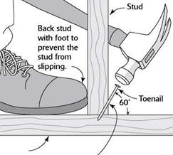
TOENAILING BASICSПодпись: Bottom plate Start the nail at a 60° angle, about 1 in. from the end of the board. Подпись: When it's not possible to drive a nail directly through one piece of wood and into another, join them with a toenail.Driving a couple of nails through the side of one 2x into the edge or face of another creates a strong connection. This is a good way to join two 2xs at a right angle. But sometimes this isn’t possible, either because the board is too thick or because its face is not exposed. That’s when you resort to driving a nail at an angle, or toenailing.

To toenail two boards together, hold the nail at a 60-degree angle and start it about 1 in. from the end of the board. If the nail angle is not correct, the connection between the two pieces of wood will not be as strong. Back up the wood with your foot to hold the board in place as you toenail. With practice, you’ll soon gain skill, speed, and confidence.

Подпись: The girders that support the joists need to break over a post. [Photo by Don Charles Blom]

attaches to the pier post and holds it in position. Secure a TT-in...

read more

EXAMPLES FROM THE DEMONSTRATION PROJECTS

Подпись: Phoenix, Arizona Open-space in Cimarron PUD Подпись: Tulsa, Oklahoma A majority of the projects in the Joint Venture for Affordable Housing (JVAH) were developed under some version of Planned Unit Development zoning or subdivision regulations.
Knoell Homes, developer of Cimarron, the’JVAH Project in Phoenix, saved at least six months by utilizing the PUD approach instead of applying for rezoning under the standard sub – _ division ordinances. This time saving reduced interest cost by approximately $106,000 or about $415 per unit. The cost reduction was passed on to the home buyers.

Rick Counts, former Phoenix Planning Director, expressed his frustration that PUDs require Home Owners Associations (HOAs). Many builders do not want to involve themselves with HOAs, and avoid using PUDs for that reason.

Hood Enterprises, developer of Innovare Park, applied for a...

read more

STEP 5 BUILD MIDSPAN SUPPORT FOR JOISTS

Unless you are building on a slab, you’ll prob­ably need to provide midspan support for the floor joists. Without additional support some­where between the sills, the joists can be over­spanned, resulting in a finished floor that sags or feels bouncy. A friend once took me through

STEP 5 BUILD MIDSPAN SUPPORT FOR JOISTS

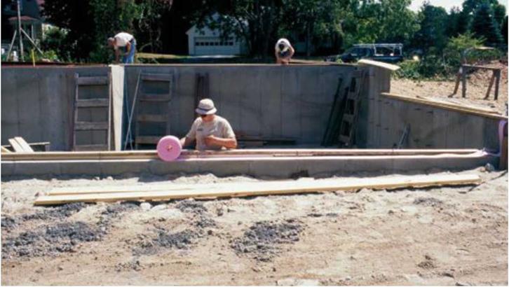
Use sill seal to block drafts and insects. Installed between the sill and the foundation, sill seal provides a resilient layer of insulation, filling in small gaps and helping maintain an effective barrier between indoors and out.

[Photo © Mike Guertin]


his 18th-century home in rural Connecticut. The beautiful, hand-hewn floor joists in the basement were fascinating—dry, free from rot and termites—but far overspanned. Upstairs, it felt like walking on ocean waves...

read more

MAKING A BOLT-HOLE MARKER

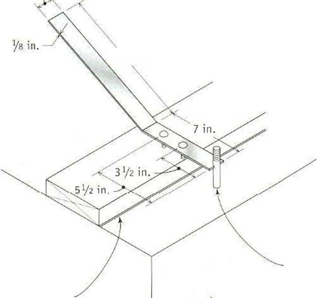
Подпись: 1У2 in.Подпись: Anchor bolt Подпись: 11 in.Подпись: CnalklineMAKING A BOLT-HOLE MARKERSelect an 18-in. by іУг-іп. by Vs-in. metal plate strap.

Cut a notch in one end of the strap so that it will fit around a Уг-іп. or 5/s-in. bolt. From the center of the notch, measure back 3!/г in. for a 2×4 plate and 5V2 in. for a 2×6 plate. Drill holes at those points and insert 3/i6-in. by 3/Vin. stove bolts. Put a bend in the plate strap to make it easier to use.

Подпись: Slab or foundationA bolt-hole marker makes it easy to transfer the bolt location to the sill in preparation for drilling a hole.

MAKING A BOLT-HOLE MARKERПодпись: AN ELECTRIC DRILL IS GREAT FOR BORING HOLES. Use a spade bit in an electric drill to bore bolt holes through a wood sill.

Install sill seal and termite shields

Sweep the foundation clean of debris, then put down a layer of sill seal insulation where the sills will he located (see the photo on the facing page). Sill seal does just what its name says...

read more

Urban Residential Drives

Either type 1 or type 2 drives (Fig. 2.49) may be used in urban areas. If used in urban areas, the radius and flare dimensions may be reduced so that the apron does not extend past the back of the sidewalk, or past the right-of-way line if there are no sidewalks. The desirable minimum radius for type 1 drives, when the through highway is curbed, is 15 ft (4.6 m).

Three methods are shown in Fig. 2.50 for designing driveways between the curb line and sidewalk to provide for turning vehicles. Other designs may be used if they are approved for use by the local governmental agencies responsible for maintenance of the project. Additional details are shown in Fig. 2.51 when the tree lawn is less than 6 ft (1.8 m)...

read more

Rural Driveway Geometries

Rural residential drives and field drives should normally conform to the type 1 design shown in Fig. 2.49 (Ref. 14). New drives should intersect the highway at an angle between 70 and 90°. In some cases, however, it may be necessary to retain existing drive angles that vary from these desirable angles.

If the project involves existing drives, the existing width is normally retained unless it is less than 12 ft (3.7 m). In that case, it should be widened to provide a 12-ft (3.7-m) throat width. In the case of new drives, the width should normally be 12 ft (3.7 m). If the new driveway is a combined drive between two properties, the width should nor­mally not exceed 24 ft (7.3 m)...

read more

DRIVEWAY DESIGN

1.10.1 Location

Part of the process in obtaining a driveway permit is to determine where the driveway will be located. The following guidelines may be used to establish this location.

Wherever possible, drives should be located in accordance with the intersection sight distance criteria (see Table 2.3). Special consideration should be given to the location of drive access to high-volume traffic generators such as shopping centers and industrial plants and parks, as well as other types of development having similar traffic characteristics. These should be treated as standard intersections with appropriate spacing to the nearest intersection. A driveway serving all directions of traffic should be located a minimum of 600 ft (183 m) from the nearest major highway or street inter­section...

read more

Water Content

A fundamental parameter that characterises the water movement in pavements is the water content. This provides information on the condition of the road layers regarding the moisture saturation stage, which controls the main parameters in the governing equations for water flow (see Chapter 2, Section 2.8). A number of meth­ods are available for measuring water content. They can be divided into destructive methods (gravimetric methods) and non-destructive methods that provide indirect measurements of the water content.

3.2.1 Gravimetric Method

Water Content Подпись: (3.1)

The simplest and most widely used method to measure the soil water content is the gravimetric method where a soil sample is taken and weighed, dried in an oven at 105 °C for 24 h and then reweighed...

read more