Category Stone Matrix Asphalt. Theory and Practice

Longitudinal Porosity behind the Center of the Paver

Figure 11.21 schematically represents a phenomenon caused by the improper dis­tribution of a mixture with augers. The distribution of a mixture along a paver screed should be checked. If the mixture is not properly distributed across the full width of the paver screed, streaks of porosity may become obvious. Another cause may be the location of the augers’ driving unit (gear box) in the middle of its width.

11.8.2.2 Longitudinal porosity (off center)
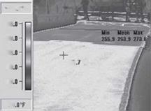
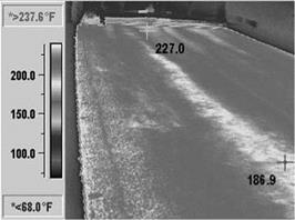
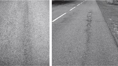
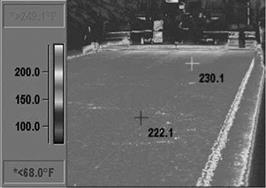
image126Longitudinal porosity parallel to the direction of spreading but not centered behind the paver appears fairly often (Figures 11.22 through 11.24). It may be caused by either of the following:

Longitudinal Porosity behind the Center of the Paver

Longitudinal Porosity behind the Center of the Paver

image128

FIGURE 11.19 Manually corrected edges of a working lane with cooler temperatures and higher porosity.


image129

FIGURE 11.20 Position of manually corrected and leveled edges—an infrared image. (Photo courtesy of Kim A. Willoughby, WSDOT, United States.)


image130

FIGURE 11.21 Longitudinal porosity behind the center of the paver.


image131

FIGURE 11.22 Longitudinal porosity off the center of the paver.

image132

FIGURE 11.23 Examples of drop in mixture temperature due to longitudinal porosity in the spread lane. (Photo courtesy of Kim A. Willoughby, WSDOT, United States.)

(a) (b)

image133

FIGURE 11.24 Longitudinal porosity: (a) on a new SMA pavement and (b) pavement dam­age in a porous area. (Photos courtesy of Krzysztof Blazejowski.)

11.8.2.3 Porosity in Other Distinctive Places

Porosity may also be found as follows on an SMA course:

• At the beginning or end of a work site

• In irregularly shaped spots

• At the edge of a compacted course

Porous spots (areas) occur fairly frequently at the beginning or end of a work site when spreading an SMA (or other asphalt mixture) course. This chiefly results from some difficulties with the correct start of laying by a paver (sometimes called take off). Because the beginning of a work site cannot be cut off and removed, such areas of porosity appear mostly at the beginning of a spreading shift (Figure 11.25).

A similar result happens with the manual spreading of mixtures for some length at the beginning of paving followed by compacting with rollers. Manual work can­not equal the efficiency of placement with a paver, which provides more than 80% of the initial compaction. The effect is evident—the course in that area is uncompacted and uneven. Other places that were manually placed because there was no room for a paver look similar (Figure 11.26).

11.8.2.4 spot porosity

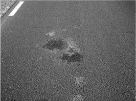
As mentioned before, pockets of porosity appear cyclically now and then (Figures 11.27 and 11.28). Their cause is not easy to explain. Maybe the paver was setup incorrectly or, more frequently, perhaps there were pieces of cool mixture in the SMA or segre­gation was still occurring in that stage of mixture production. Or the cause may be something entirely different and difficult to determine.

Continuous Porosity by the Edge

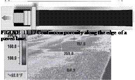
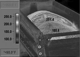
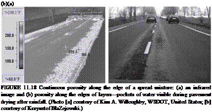
This defect appears in a continuous way along the edge of a layer (Figures 11.17 and 11.18). It is mainly brought about by the following:

image121

FIGuRE 11.13 Formation of streaks or mixture pulling due to incorrect setup of paver screed segments.

image122

FIGuRE 11.14 The effects of an incorrect paver setup, temperature in degrees Fahrenheit. (Photo courtesy of Kim A. Willoughby, WSDOT, United States.)

image123

FIGuRE 11.15 Area of an uncompacted cool mixture during a paver standstill (a zone of cooling mixture that is inaccessible to rollers).

image124
Подпись: '
Подпись: ill

FIGURE 11.16 Paver standstills and their effects—infrared images. (Photos courtesy of Kim A. Willoughby, WSDOT, United States.)

• Badly adjusted mechanism of mixture distribution through the augers or improper operation of the augers (insufficient quantity of a mixture sup­plied to the screed edge)

• Length of augers too short in comparison with the board width (several board segments with no additional feeding segments applied)

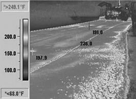
The porosity of a layer is usually easily seen when the surface is wet (Figure 11.18.b). Another problem (less often observed) can be caused by manual raking of a mixture along the edges of a spread lane (Figures 11.19 and 11.20). Unfortunately, leveling a newly spread mixture with rakes or shovels is the customary manner of some paver teams. Manual raking cannot produce the same level of uniformity as mechanical leveling, leading to cooler portions and porous areas in the mat.

Paver-Made Streaks

Let us suppose that an adequately hot mixture is delivered to the job site. Nevertheless, badly adjusted paver elements (in the given examples, badly arranged screed seg­ments) may bring about the formation of porous areas in the course (streaks). Figure 11.13 presents an example of streaks pulled by a paver during laying. Figure 11.14 presents the same effect but photographed with an infrared camera.

11.8.2.1 Paver Standstills

One of the main principles of laying SMA is avoiding a paver standstill. Almost every time the paver is immobile, uncompacted areas behind the machine are the result (Figure 11.15). This effect is heightened if the mixture contains modified binder (higher stiffening of the mixture during cooling down). Figure 11.16a and b presents infrared camera photos of mixture cooling down during a paver standstill.

Construction-Related Problems

The laying of too cool a mixture may result in a course with a considerably large amount of air voids (see Section 11.6). That is an obvious matter; however, quite often the accelerated cooling of a mixture takes place in particular areas during its laying. Such places have been defined as having porosity of different types.

The figures in the sections that follow are photos taken with an infrared camera. The Fahrenheit scale of temperature has been placed on each of them. They show various causes of mixture cooling, followed by thermal differences resulting in poor quality.

image120

FIGuRE 11.12 Distribution of asphalt mixture temperature after transport to the work site during discharge into the paver. (Photo courtesy of Kim A. Willoughby, WSDOT, United States.)

Transport of a Mixture to the Working Site

When it is cold and the construction site are far away, we usually console ourselves with the idea that the mixture is hot inside so the cool crust may be somehow stirred into the hot mix and warmed up in the paver. The mix really is hot inside, as shown in Figure 11.12. Typical cracks in the cool crust formed on the surface of the trans­ported mixture and its deeper cooling down by the truck’s sideboards may also be noticed. That is why it is always worth using trucks that have well-insulated boards and are tightly covered.

In cold seasons there are little chance that delivered mix will have thermal uni­formity. Usually after discharge of the mixture into the paver hopper there are many cool or poorly heated fragments in the mixture. Frankly, it is not wise to be under the illusion that the cool pieces can be stirred into the mix and warmed up and that the mixture will again be homogeneously hot (though the use of MTV vehicles can help—see Chapter 10).

Mixture Production in an Asphalt Plant

When storing a finished, hot mixture in a silo, the mixture closest to the walls of the container is subject to gradual cooling. As storage time increases, the amount of cool mixture is likely to rise substantially. If the SMA contains modified binder, its stiffening process proceeds much faster. Moreover, we may face additional trouble with cool mixture stuck to the walls of the silo unless the silo is heated. Also, if the silo chutes are not heated, problems with discharging the mixture out of the silo can occur.

Problems of Manufacture and Transportation

Most questions related to maintaining a suitable temperature during the mixture’s manufacture have been regulated by commonly known technical specifications (e. g., standards, guidelines). These questions are discussed in Chapter 9. Simply speaking, there are two main problematic instances in the matter of SMA manufac­ture temperatures—when the temperatures are too low or when the temperatures are too high.

Too low a manufacturing temperature of a mix prevents the formation of a correct and complete asphalt binder film. Too low a temperature can be visually recognized; aside from visible uncoated aggregate pieces, the appearance of the mixture seems to be matte. Since SMA contains a considerable amount of binder, it should be glossy and glisten “glow wormly” (namely, like glow worms) at a suitable temperature.[69] Too high a manufacturing temperature increases the threat of binder draindown from the aggregate and excessive aging of the binder. Loading the overheated SMA into a silo runs the risk of getting into trouble with excessive draindown. To check SMA susceptibility to draindown after mixture overheating, one ought to test it when the SMA is at a temperature 15°C (or 25°C) higher than the recommended manufac­ture temperature (see Chapter 8).

PROBLEMS RELATED TO TEMPERATURE AND Laying Techniques

Thermal problems occurring during the manufacture and placement of SMA are often underestimated, and yet they can lead to significant defects in a new course and reduce its working lifetime. It has already been indicated in Section 11.6 that the placement of a cool SMA mixture may result in an excessive content of voids.

Aside from problems directly connected with the temperature of a mixture, the effects of wrongly adjusted equipment during placement may be observed. Now and again errors in laying and the effects of an unsuitable mixture temperature superim­pose onto each other. These problems may be divided as follows:

• Manufacture and transport

• Unsuitable temperature of an SMA ingredients during manufacturing and storing in a silo

• Wrong methods of transporting a mixture

• Laying

• Improper temperature of the supplied mixture

• Adjustment errors by the paver and in general methods of laying

Infrared cameras are increasingly being used to analyze thermal problems. Results of such research efforts may be found in several publications (Pierce et al., 2002; Stroup-Gardiner et al., 2000; Willoughby et al., 2001).

SMA SEEPAGE AND PERMEABILITY TO WATER

SMA surface seepage is directly related to excessive porosity of a compacted mixture (see Chapter 12) and the condition (watertightness) of the course situated just under the SMA. When assessing the watertightness of an SMA course, one must not forget that water permeability is determined not only by the contents of voids on the surface of a compacted course but also by the shape and interconnectedness of the inner pores. Finally, most national regulations and numerous publications recommend a [68]

image118

FIGURE 11.10 The surface of an SMA course just after spreading at too low a temperature. (Photo courtesy of Krzysztof Blazejowski.)

image119

FIGURE 11.11 Seepage of water through an SMA layer. (Photo courtesy of Bohdan Dolzycki.)

limit of 6.0% (v/v) air voids in a compacted course, above which a course becomes partially permeable to water.

A tight intermediate course under the SMA, which prevents the penetration of water and water vapor deep into the pavement, is conducive to the development of SMA surface seepage (Figure 11.11).

TOO POROUS SMA STRUCTURE

Just as it is possible to find an SMA course that is too closed, so too it is possible to find a course that has too high a void content. This problem may occur over very large areas, which are marked by excessive porosity. Local porosity over smaller areas, is described in Sections 11.8.2.3 through 11.8.2.9.

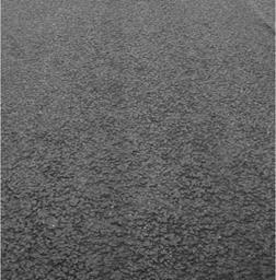
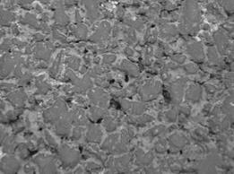
The issue of how open the SMA structure should be has been debated for some time. True enough, we happen to find a quite porous SMA structure every now and then. An investor or may owner sometimes agrees to leave in place an SMA that is too closed (after an antiskid treatment); unfortunately an SMA that is too open more often falls victim to a road-milling machine. An open structure (Figure 11.9) of a mixture consisting of lots of mutually connected pores is conducive to water and air penetration (see Chapter 12), which results in a shorter service life of the course.

An excessively open structure of an SMA course may be caused by any of the following: [67]

image117

FIGURE 11.9 A close-up of an SMA course surface with a high content of voids. (Photo courtesy of Krzysztof Blazejowski.)

High contents of free voids in a compacted SMA course may result from a mistake made while designing the mixture. Usually the cause is a result of one of the following:

• An undue shifting of the grain size curve to the right and an increase of the coarse aggregate fraction to greater than 80%, with a simultaneous decrease in both the sand fraction and the filler, plus a reduced content of binder—as we remember, an increased amount of material on the 2.0 mm sieve requires an increase in the binder content to fill the voids of an SMA mixture

• A reduction of SMA binder contents, sometimes practiced for the sake of economy

• The application of excessive temperatures and increased energy during the compaction of samples in the laboratory,* resulting in an incorrect mixture design.

If porosity appears over larger areas and is not an error of composition, one may expect that the number of rollers or passes have not been suitably selected or that too cool a mixture has been spread. Sometimes the difference may be noticed when watching the layout structure of aggregate grains. Grains of a mixture spread at too low a temperature look as if they have been pulled by the paver screed; they are not arranged tightly side by side (Figure 11.10).