Category Stone Matrix Asphalt. Theory and Practice

FINISHING THE LAYER

Some countries require special finishing techniques for SMA surfaces. Those requirements are described here.

10.7.1 G ritting

Applying a layer of grit to the finished surface is often specified. Why has gritting been applied? Soon after placement, the SMA layer is characterized by relatively low friction (the so-called postconstruction slipperiness) caused by a thick film of binder on particles of aggregate. Spreading additional aggregate on the surface of the hot SMA, followed by rolling (to embed the grits) is aimed at breaking the binder film on the coarse particles. Due to its microtexture, well-embedded grit breaks the water film, hence increases the skid resistance of SMA.

Without gritting, the process of rubbing the binder film off the aggregate particles that provide the SMA macrotexture proceeds slowly under the action of traffic, first in the wheel paths, and then, after some time, all over the roadway surface. This pat­tern of wear brings about the development of nonuniform friction characteristics of the wearing course. Dutch researchers (Jacobs and Fafie, 2004) have demonstrated low values of friction coefficients appearing on both a dry and a wet SMA course:

• On a dry pavement in summer, the binder film on the surface of the aggre­gate particles softens at high temperature, changing the binder film into a lubricant, reducing the friction between tires and aggregate particles.

• On a wet pavement, because of the thick binder coat, the aggregate micro­texture is not able to break a water film on the surface of an SMA course.

If the SMA contains a PMB, the binder film remains intact for a longer period of time.

Therefore some additional solutions for enhancing the friction coefficient should be applied to increase the friction in the early stages of trafficking the roadway while the binder film remains intact. Some observations prove that it might take as long as 6 months to rub off the binder film on the coarse particles.

Macrotexture

In some countries, particularly where surface properties are high priorities for a wearing course, in addition to other parameters, requirements for macrotexture are also laid down. The British requirements (HA MCHW, 2008) for mixtures with an upper (D) aggregate size of 14 mm or less, stipulate a minimum 1.3-mm macrotex­ture depth[64] (measured using the volumetric patch method described in EN 13036-1) for high speed roads at the moment of opening the road to traffic. In some other countries the requirement for the macrotexture depth is a minimum of 1.0-1.2 mm, but this requirement usually does not apply to fine graded SMA 0/7 or 0/8 mm.

10.6.2 Nuclear Gauge Density Measurements

In many countries, nuclear gauges are used for field testing compacted asphalt layers. If well-calibrated with core samples, nuclear gauges are convenient tools for rapid testing of field density.

In a report by Brown and Cooley (1999), they pointed out that the application of lev­eling sand and dynamic correction factors improve the accuracy of the density tests.

British guidelines (BS 594987:2007) provide a protocol for calibrating and oper­ating indirect density gauges, including gauge operations, initial calibrations, and consistency of calibration.

Compaction Factor as a Quotient of the Bulk and Maximum Densities

Calculating the quotient of the bulk and maximum (the so-called theoretical maxi­mum density [TMD] or the Rice density after ASTM 2041) densities is a popular method of determining the compaction factor. The requirement for compaction of an SMA layer is a minimum 94% (of the maximum density) according to the NAPA SMA Guidelines QIS 122; that makes upto 6% (v/v) of air voids allowable after compaction. In this case the reference density does not depend on conditions for preparing laboratory specimens. As in the previous method, densities obtained in a laboratory during mix design are not taken into account; results from testing the den­sity of a mixture taken from an asphalt plant during trial production are recorded.

The essential strength of that method is making the compaction factor free from various conditions for preparing specimens. The possibility of making mistakes in determining the reference density in a laboratory obviously disappears.

Compaction Factor

Almost all documents on SMA reviewed for the purposes of this book contain the compaction factor as a specified requirement. As in many other cases, the differ­ences between European and U. S. specifications are clear.

That factor has been defined differently in different countries. The differences are grounded in the different reference density used related to the bulk density of the layer achieved on the construction site. That is the source of the sharp differences in numerical values: from 94% (the United States.) to 98% (Norway). The description of two basic definitions of the compaction factor follows later on.

Mix design After construction End of service life

FIGURE 10.13 Change in the content of air voids in an SMA layer. (From Voskuilen, J. L.M., Proceedings of the 6th International Conference Durable and Safe Road Pavements, Kielce [Poland], 2000. With permission.)

10.6.2.1 Compaction Factor as a Quotient of Bulk Densities

In European practice, compaction factors based on a quotient of bulk densities have been commonly used. That quantity is calculated in percent according to the formula

c = Ps – -100%

Psl

where

c = compaction factor, %

ps = the bulk density of a specimen cut out of a pavement, g/cm3

psl = the bulk density of a specimen prepared of the same constituents and com-
pacted in laboratory conditions (so-called reference specimen), g/cm3

The most common requirement for the SMA compaction factor calculated accord­ing to this equation is c is at least 97%, though the requirement of c being no less than 98% can also been found.

A sine qua non for the correct calculation is taking into account the following assumptions:

• The SMA mixture used for preparing reference specimens compacted in a laboratory should come from the mixture being placed (e. g., from a truck just leaving the asphalt plant).

• Compaction conditions for reference specimens, specifically the tempera­ture and compaction, should be adequate to meet the real conditions pre­vailing on the construction site.

• The control specimens cut out of the pavement should not come from areas close to the edges or at the beginning or end of a working lot.

The German guidelines for compacting asphalt surfacing (M VA 2005) have included additional procedures and directions to facilitate control of the compaction process for difficult-to-compact mixtures. The compaction factor of an asphalt layer, denoted as k, is calculated according to the equation:

к =—P——— 100%

P

lab/

s (E=50)

where

p/ = the bulk density of a specimen cut out of a placed layer pslab(E=50) = the bulk density of a specimen prepared in a laboratory with the use of 50 strokes of a Marshall hammer on each side of a specimen

The bulk density of laboratory specimens is determined on material prepared with 2 x 50 strokes of a Marshall hammer. The compaction temperature should be appropriate for the applied binder. Due to various interpretation problems and mis­takes in the calculation of the index k, the new German guidelines (M VA 2005) have introduced an additional parameter—the compaction index K referring to the bulk density achieved on the construction site relative to the maximum density

K = ^ • 100%

P”

where

K = compaction index, %

psb = the bulk density of a specimen cut out of an executed layer

p" = the maximum analytical density of a given mixture

Having substituted the maximum density, the values of the compaction index will be higher than 94%. The method of using the quotient of two bulk densities for deter­mining the SMA compaction factor has been called out by the European standard EN 13108-20. Its clause C.3 stipulates that the reference density for indicating the compaction factor is the bulk density. The standard also provides that detailed condi­tions for preparing specimens and determining that density using EN 12697-5 and EN 12697-6 shall be declared.

TESTING THE FINISHED LAYER

A series of acceptance tests are carried out after finishing the placement of a mix­ture. They usually comprise measuring the content of air voids and the compaction factor, conducted on specimens of cores taken from the finished pavement. In many countries, nuclear density gauges are used for testing the homogeneity of compac­tion. When this is the case, cores are only required for calibration and comparisons with the nuclear gauge. Other properties checked on finishing the layer are skid resistance and the macrotexture depth. The methods used for these tests depend on national specifications.

10.6.1 Air Voids in a Compacted SMA Layer

The content of voids in the compacted SMA layer is the most commonly found parameter checked at the acceptance of a finished layer and is always mentioned as a fundamental. According to most analysis documents worldwide, the content of air voids should be lower than 6.0% (v/v). Lately in German guidelines ZTV Asphalt-StB 07 (September 2008 issue), this value has been lowered to 5.0% (v/v). This is the requirement most closely related to the durability of the compacted layer, including its susceptibility to water permeability, frost heave, and deicers. In countries with no significant drops of temperature below 0°C, higher contents of voids in the SMA layer (e. g., up to as much as 5-8% [v/v]) have usually been permitted.

An insufficient content of voids in a layer is also disadvantageous; recent expe­rience shows that less than 3% (v/v) brings about the risk of premature rutting. It has been underlined in the literature (Voskuilen, 2000, Voskuilen et al., 2004) that when designing SMA with a determined content of voids in laboratory speci­mens (usually 3-4% [v/v]), one should remember that the final amount of voids in a compacted layer depends, among other things, on the arrangement of skeleton particles and voids among them. The air voids achieved in a layer on a work site are different from those achieved in the laboratory, just as particles compacted using a Marshall compactor are arranged differently than those that are rolled. Some authors (Voskuilen, 2000) also claim that during the life of the pavement, the content of voids in an SMA layer decreases due to the gradual decrease of voids in the chipping skeleton (e. g., postcompaction, crushing particles). That is why, for instance, in the Netherlands, designing SMA with an initial (laboratory) content of voids at the level of about 5% (v/v) has been practiced. Then, after some time of service, the air void content in the field was lowered to 2-3% (v/v) (Figure 10.13).

Final Remarks

The layer edge should be rolled with a machine fitted with a side-roll; this will enable suitable compaction of the area close to the edge. The drums of a roller should be moistened with water, which should protect them against mastic adhesion and drag­ging particles out.

10.5 pLAcEMENT of sMA IN KOMPAKTASPHALT TEcHNIQuE

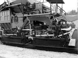
The Kompaktasphalt method consists of placing two layers of a pavement in one pass of a specially designed paver (Figure 10.12). Typically the paver places both an SMA and asphalt concrete in one pass. The first attempt at such a laydown occurred

image104

FIGURE 10.12 Special paver for the placement of two layers in one pass with an SMA wearing course (A2 highway in Poland), an example of Kompaktaspha. lt technology. (Photo courtesy of Konrad Jablohski.)

in 1995 Germany and was made by Elk Richter of Fachhochschule Erfurt and the company Hermann Kirchner GmbH&Co KG on Highway A4 (Richter, 1997). In December 1998, also in Germany, a special modular paver was used for the first time (Utterodt and Egervari, 2009). This technology has been chiefly applied in Germany. Undoubtedly, the simultaneous placement of two layers has a number of strong points. It is enough to mention just the following:

• Excellent interlayer bonding (i. e., the “hot-on-hot” placement)

• Great thermal capacity of the two layers together (thickness of 10-12 cm), giving more time for compacting, especially on cool days

• Rapid progress in work (two layers at the same time)

The use of the Kompaktasphalt technology carries with it some additional require­ments for the construction site organization:

• The mixture intended for a particular site comes from two, sometimes even three, asphalt plants with sufficient capacity to supply the paver.

• An adequate number of transport vehicles are essential to haul mixtures from asphalt plants to the construction site.

This frequently adopted scheme provides for the placement of an asphalt concrete intermediate layer and an SMA wearing course. Various thicknesses and gradation of SMA layers are used, with 4-cm of SMA 0/11 mm and 3-cm of SMA 0/8 mm being used most often.

Time Available for Compaction

The time available for compacting the layer depends mainly on the following condi­tions during placement:

• The mixture temperature behind the paver

• The air and surface temperatures and wind velocity

• The layer thickness

The matters of temperature are elaborated on in Section 10.3.2.

In extremely adverse weather conditions, the time for compacting is counted in minutes and is often less than 5 minutes. After that time, the mixture temperature falls to a level at which the high viscosity of binder makes the movements of the mix­ture particles impossible. If the SMA layer has to be placed in difficult conditions, the following organizational issues should be remembered:

• Using the best possible insulation during SMA mixture delivery

• Closely coordinating the mixture deliveries in relation to the spreading speed with no stoppages and shutdowns of the paver or trucks delivering mixture to a work site

• Discharging consecutive mixture deliveries to the paver hopper before it is completely emptied

• Effectively heating of the paver screed

• Maintaining the proper paver speed to avoid the following:

• Decreased effectiveness of the paver compaction

• The risk of dragging chipping particles out by the screed

• Keeping the rollers close behind the paver and having more of them than when compacting in good conditions

• Calculating the limited time of effective rolling caused by the drop of mix­ture temperature in the layer; being aware of weather conditions, the tem­perature of a delivered mixture, and the layer thickness, one can roughly estimate the time required for compacting using ready-made curves, mea­suring the layer cooling rate, or calculating it with the use of computer software such as PaveCool or MultiCool.

Number of roller passes

Usually six to nine roller passes are enough to compact an SMA mixture. Moreover, compaction should not cause squeezing of the mastic onto the surface. The number of passes with vibrations should be limited to the indispensable minimum (most frequently, three).

On many construction sites or at the start of a new SMA mixture, it is recom­mended that the effectiveness of rolling in relation to the number of passes and type of rollers be tested on a specified section. The increase in density with more rolling passes is monitored with, for example, a nuclear density gauge, and the number of passes to reach the desired density is determined.

Speed of the Rollers

The speed of the rollers should be controlled and should be slow. According to the NAPA SMA handbook QIS 122, the speed of a roller during rolling must not exceed 5 km/h. In one of the British guidelines, the speed of the rollers should normally be between 4 and 6 km/h (SEHAUC, 2009).

Rolling with vibration at a reduced speed improves the effectiveness of compaction. However, doing so may lead to crushing particles and squeezing mastic out on the sur­face of a layer. Therefore great caution should be exercised, and vibration should be turned off if need be. Rollers with a speed control option enable automatic control to disengage vibrations during braking and changing direction. It should be kept in mind that rollers with speed control require a longer braking distance and skillful control.

Sequence

Various compaction sequences are adhered to. Generally speaking, every road-en­gineering company works out its own procedure after some time. By and large, the standard rule states that the paver is followed by static rollers first and then by vibra­tory rollers. Final passes are always carried out by static rollers, which finally level the surface, removing traces of rolling from it (the so-called finishing). When using

image103

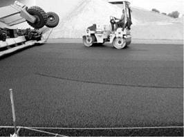
FIGURE 10.11 The particular way rollers approach the paver, with a turn being made right behind the paver. (Photo courtesy of Konrad Jablotiski.)

rollers with new types of vibration, it is worthwhile to consider the manufacturer’s

suggestions.

One of the more interesting techniques of rolling consists of the first roller behind the paver (the breakdown roller) making a slight turn when it approaches the paver (Figure 10.11). The remaining rollers operate without making the turn by simply reversing direction. This technique, among others applied in the Kompaktasphalt, is aimed at achieving better layer smoothness.