Category Stone Matrix Asphalt. Theory and Practice

TOO CLOSED SMA STRUCTURE

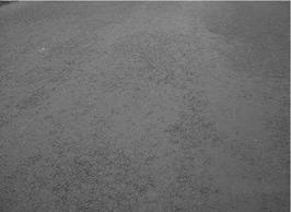
It happens that, after the completion of an SMA course, a sight reminiscent of mas­tic asphalt may unfold before the observer’s eyes (Figure 11.8). Such a closed SMA structure means utter failure and the likely removal and replacement (possibly by recycling) of the layer. This kind of problem is directly connected to the discussion in Section 11.2 about fat spots of mastic (without segregation) but usually occurs over most or all of the layer.

Reasons for such a significant setback include the following:

• Errors of mixture design

• Too much mastic in relation to the voids’ volume among the compacted coarse aggregates

• Upward designing of a gradation curve in the filler-sand fraction

• Use of weak aggregates

• Errors of compaction—application of excessive compaction energy (too high a vibration amplitude), which causes the crushing of grains and their closer arrangement, thus reducing voids meant for mastic

• A combination of these two causes—an application of weak aggregates is conducive to such a superposition; then we can speak about an error of design (selection of aggregates) and an error of placement (excessive energy of compaction).

If we happen to observe a large, closed SMA surface accompanied by a distinc­tive odor, it is worthwhile reading Section 11.11.

STABILIZER LUMPS

Stabilizer lumps occur rarely, but sometimes they bring fairly unpleasant consequences. The problem lies in the fact that symptoms may only be seen some time after the placement of an SMA course. Results such as the following are quite spectacular:

• Initial formation of bulging spots in a newly made course

• A spot of mixture that separates from the mat

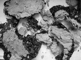
Both cases are caused by lumps or pieces (Figure 11.6) of an undistributed (unmixed) stabilizer of loose fibers. Moisture absorbed by a stabilizer is able to lift

image112

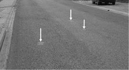
FIGURE 11.4 An example of randomly scattered circular fat spots of about 1-15 cm in diameter. (Photo courtesy of Krzysztof Blazejowski.)


image113

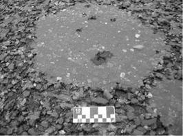
FIGURE 11.5 A circular fat spot about 20 cm in diameter, enlarged. (Photo courtesy of Krzysztof BlaZejowski.)


image114

FIGURE 11.6 A big lump of stabilizer incorporated into an SMA course, after removal. (Photo courtesy of Krzysztof Blazejowski.)


image115

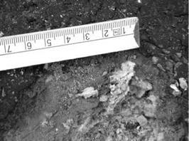
FIGURE 11.7 Stabilizer lumps incorporated into an SMA course. (Photo courtesy of Marco Schunemann.)

image116

FIGURE 11.8 The closed structure of an SMA course over a large area. (Photo courtesy of Krzysztof BlaZejowski.)

an SMA course enough to be discernible to the naked eye. It also causes the mixture to ravel and create pot holes (Figure 11.7). These situations may happen as a result of the following:

• Wet, loose fibers were applied.

• Loose fibers was added into the pugmill too late—namely, after binder dosing.

• Wet-mixing time was excessively shortened.

• Stabilizers of poor quality were used.

. Fat Spots of Mastic without Segregation

If porous spots are not visible around the fat spot, this is not a case of classic segrega­tion. We may suppose that the fat spot appeared because of an excess of mastic volume (an error of design). It may also have been caused by too much energy applied during compaction (improperly adjusted or unskillfully applied vibration); this will lead to the crushing of the coarse aggregate skeleton and the squeezing out of the mastic. Then the surface with the bleeding mastic will make up a major part of the surface (which, simply put, is any area where bad compaction was applied). A related prob­lem, described in Section 11.5, describes an SMA surface that is too closed or tight.

11.1 SMALL CIRCULAR FAT SPOTS

Small fat spots with a circular shape of approximately 3-20 cm in diameter may appear on a laid SMA course, randomly scattered without any visible order of occur­rence (Figures 11.4 and 11.5). This type of fat spot hardly ever appears. As usual, their composition should be checked. Most often, mastic and stabilizer (especially loose fibers) can be found in them. They are most often caused by insufficient mix­ing of the SMA components (i. e., insufficient wet-mixing time at the mixing plant).

Fat Spots of Mastic with Segregation

An area with a definite shortage of mastic adjacent to the fat spot (visibly porous) is a clear sign that this is a case of an SMA segregation—namely, separating the coarse aggregates from the mastic. If the quantities of all the ingredients have been properly selected, the high accumulation of one component in one location will result in a reduced quantity of that component in another. When an excess of mastic (fat spot) appears somewhere, the coarse aggregate content rises elsewhere, so the total sum of the components remains constant. Figure 11.2 presents a classic fat spot in a segre­gated SMA mixture. Figure 11.3 shows the difference between fat spot and adjacent porous section and a close-up of the mastic-rich area.

It is worth emphasizing that such segregation may happen for one or more of the following reasons:

• Substandard production of an SMA mixture

• Lack of a stabilizer, its improper metering, or its poor quality

• Excessive production temperature

• Too short a time of mixing components

• Too long a storage time of a mixture in an asphalt plant storage silo

• Improper laydown of SMA (with an improper setup of a paver)

image110

figure 11.2 SMA mixture segregation—separation of mastic from coarse aggregates. (Photo courtesy of Krzysztof Blazejowski.)

LONGITUDINAL FAT SPOTS OF MASTIC (SEGREGATION)

Mastic fat spots may be distinguished from binder fat spots using a tool to check the composition of a particular fat spot. All the elements that make mastic—binder, filler, fibers and sand—can usually be identified in a cross section of a fat spot. It is neces­sary to examine what is going on around the fat spot to discover its cause. Usually there is one of two sets of conditions—with segregation or without segregation.

LONGITUDINAL FAT SPOTS OF BINDER

Longitudinal fat spots are the most frequently seen defects when using SMA. Such spots may be defined as areas with an excess of binder or mastic that are shaped longitudinally and are parallel to the path of the paver.

There are two types of longitudinal fat spots—binder fat spots and mastic fat spots—which differ only in the content of the fat spot’s components.

Longitudinal fat spots (Figure 11.1) contain, firstly, some amount of binder appearing on the surface of a course. They are easily recognizable simply by scratching the fat spot with the metal stem of a thermometer. A thin binder layer

image109

FIGURE 11.1 Longitudinal fat spots of binder. (Photo courtesy of Bartosz Wojczakowski.)

is visible on the surface of the SMA course, with regular SMA underneath. Thus such fat spots are similar in appearance to mastic fat spots but with no separation of all the mastic from the coarse aggregates. They arise because of an excess of unbonded binder. They may be caused by an error during one (or more) of the following:

• Design (too much binder designed in SMA)—this type of error should be detected by the design laboratory during draindown testing; thus it happens relatively rarely.

• Production—it is more likely that an overdosage of binder will occur during mixture production (e. g., due to an inaccurate weigh scale for the binder) or because the metered amount of stabilizer proved to be too small to prevent binder draindown—that is, an inaccurate stabilizer metering system or inadequate action from the stabilizer (e. g., a granu­lated stabilizer of poor quality or one damaged by an excessive time of dry mixing[66]).

• Change in the properties of the components—this can occur any time a component is changed during the course of SMA manufacture.

• Fillers are changed and have significantly different contents of voids than previous fillers.

• PMB viscosity is too low at the production and laying temperatures (occurs especially when PMB is used for an SMA without fibers).

• Granulated stabilizer quality changes or is overpressed.

• Surface preparation—in some circumstances an excess of binder com­ing from an underlying tack coat (which may result from excess tack coat binder gathering in depressions) or mastic asphalt patches situated under SMA may be drawn up into the SMA surface by the heat of the newly placed course.

Problems

As with other asphalt mixtures, problems frequently occur with SMA, too. They may develop at the stage of design, production, or application. Some of the troubles described here also appear in asphaltic concrete or other asphalt mixtures, but a dis­tinctive feature of SMA is that its shortcomings are revealed in a particularly clear, and sometimes painful, way.

This chapter presents an arranged collection of the most common defects observed in SMA. But before we begin, two issues need to be made clear:

• Each group of problems and their probable causes are provided here based on the author’s subjective assessment derived from his experience and con­sideration. Therefore it is obvious that a reader may have a different view on a given problem or that it may have another cause.

• Always and in each case, while examining a detected problem, one should be open to investigating its various causes, including the less obvious ones. Nobody should limit himself or herself to the pieces of advice contained in this book; an open mind is the recommended approach.

An immediate “blessing” when a problem occurs is having a laboratory or pos­sibly the asphalt plant staff available to help correct the problem; these resources are becoming more widely available. The lab or plant staff can help to evaluate the materials and operations to identify the causes of the problems, such as changes in material properties, plant temperatures, moisture conditions, etc. This chapter will make it apparent that the members of the team preparing road machines and the site team are as important in the final outcome (success or failure) as other elements.[65]

Now it is time to examine with the problems in detail.

Edge Sealing

In regard to edge sealing, the following reasonable solution definitely extends the durability of a pavement and has been adopted in German practice (Milster et al., 2004):

• An extra layer of tack coat (of hot binder) is placed on the edges of pavement (between the layers), minimum 10 cm wide.

• A binder layer, minimum 2 mm thick, on a side surface of all layers, is applied (to achieve such a layer of binder, the tack coating usually needs to be repeated, or a hot sealant 2 mm thick needs to be applied in one work­ing cycle).

This sealing is aimed at protecting the pavement against water infiltration between layers and inside them.

10.6 OPENING TO TRAFFIC

Before opening up a road section with a new SMA layer to traffic, one should be sure that it has sufficiently cooled. Letting traffic go on an SMA layer while it is still warm may cause its premature rutting and the squeezing-out of the mastic. Some regulations stipulate that the opening to traffic may happen no sooner than 24 hours after finishing the placement, or at least, when the temperature in the middle of a layer drops to 30°C. The common practice is to delay the opening to traffic until the moment that the layer temperature drops to the air temperature. When an earlier opening to traffic is necessary, only light vehicle traffic should be allowed.

Edge Sealing

Gritting Execution

Grit is spread on an hot SMA mixture using one of the two following techniques:

• With a gritter installed on a roller, during the first pass of the roller there is no gritting, but during the second pass the gritting is turned on. One should remember to grit in one direction of roller movement, and to not grit when returning; when using that technique, grit particles are pressed into the hot SMA mixture (Figure 10.15).

• With a self-propelled gritter, gritting starts after rolling the layer down with the rollers, when the SMA is still hot enough and prior to the last pass of the roller. This method is seldom used.

Remember that the quantity of grit per square meter has been established for a given machine (a gritter) and for a specific passing speed. Any change to the speed

image106

FIGURE 10.15 SMA gritters installed on rollers—the gap gritter. (Photo courtesy of Bartosz Wojczakowski.)

image107

FIGURE 10.16 Movement traces of a roller after gritting a freshly made SMA layer. (Photo courtesy of Krzysztof Blazejowski.)

results in a change in the quantity of grit applied to the layer. The minimum tempera­ture of a layer being gritted is 110°C; below that temperature the grit is unlikely to stick to the SMA (Jacobs and Fafie, 2004).

Figure 10.16 shows movement traces of a roller fitted with a gritter. Spots where the roller has changed direction before the gritter was fully disengaged are visible. This is not a substantial mistake of execution; at most it is likely to spoil the aesthetic impressions of some road users. After gritting and cooling of the layer, excess grit aggregate or unbonded grit should be removed, (e. g., by sweeping).

Research has proved that gritting makes sense since it enhances SMA antiskid­ding performance in the initial period after pavement construction. When gritting is not used, better coefficients of friction are available with SMA 0/8 mm than with SMA 0/11 mm (more contact points between SMA and tire). It should be mentioned additionally that the application of gritting influences the macrotexture during the first period after construction. Grains and crushed particles of grit occupy spaces between coarse grains and decrease the macrotexture depth.

Finally, it should be clearly stated that gritting is not a way to cover or hide fat spots occurring on SMA surfaces during placement. In some cases, even gritting is not likely to conceal a fat spot, since gritting would be “drowned” in an excess of mastic (Figure 10.17).

image108

FIGURE 10.17 Gritting of chippings 2/5 mm applied over a fat spot of mastic. (Photo cour­tesy of Krzysztof Blazejowski.)

Gritting Materials

Grits usually consist of different types of aggregates, such as the following:

• Aggregate 2/5 (or 2/4) mm, cleaned and hot, applied at a rate of 1.0-2.0 kg/ m2, for SMA with a gradation of at least 0/11 mm (Figure 10.14)

• Aggregate 1/3 mm, washed and hot, applied at a rate of 0.5-1.5 kg/m2, for SMA with any gradation

• Aggregate 0.25/2 mm, washed and hot, coated with about 1% binder (m/m), applied at a rate of 0.5-1.5 kg/m2, for SMA with any gradation but preferred for SMA 0/5 and 0/8

Generally, the use of finer grains for gritting means a lower quantity per square meter. Additionally the smaller the maximum aggregate size of the SMA, the smaller the grit grains that should be used.

image105

FIGURE 10.14 Gritting particles among SMA coarse aggregates. (Photo courtesy of Krzysztof Blazejowski.)

Gritting with aggregate 2/5 (2/4) mm is not recommended for SMA in Germany because it brings about an increase in noise generated by the contact between tires and the gritted pavement, (Druschner and Schafer, 2000). However, Dutch research has not proved an increase in noise caused by the use of grit (Jacobs and Fafie, 2004).

Gritting with an aggregate coated with binder provides a durable bond between the grit and the hot SMA layer. Attention should be paid to preventing an overdose of grit to avoid its sticking to the drums of a roller and destroying the hot layer surface. An overdosing of grit uncoated with binder can produce a similar effect (Jacobs and Fafie, 2004).

It is worth knowing that in British guidance (HAUC 2009), the aggregates for gritting should have a PSV not less than 55, which is more than the PSV of coarse aggregates used in an SMA skeleton in many countries (e. g., Germany, Poland, Hungary).