Category Stone Matrix Asphalt. Theory and Practice

Control according to U. S. Documents

The distinctive feature of the contemporary U. S. approach to production control is the application of statistical methods and fines as punishment for exceeding admis­sible limits or deviations from the mix design. (Sometimes bonuses, or incentives, are also used to reward exceptional production consistency, but penalties are more common.)

The quality control methods widely employed in the United States are called quality control/quality assurance (QC/QA). These systems typically involve test­ing recently produced bituminous mixtures for the following (USACE Handbook, 2000):

• Mix components—binder content and gradation of the mineral aggregate

• Physical properties of the mixture measured on compacted Marshall or gyratory samples

• Air-void content

• VMA

• Voids filled with binder (VFB)

• Density

• Stability and flow, if required

Under QC/QA specifications, the mixture manufacturer is charged with the respon­sibility for quality production control (QC). Its laboratory’s duty is to undertake con­trol activities. Verifying the operation of QC, or QA, is the investor’s (or owner’s) responsibility. It is necessary to stress again that in the United States sliding scales of fines are imposed, depending on the statistical results of production control.

Every producer of a mixture must formulate and submit for approval a quality con­trol plan (QC plan). Broadly speaking, this type of plan[59] comprises such details as the determined features under control and the frequency of their testing, the methods for recording results, and the corrective actions taken in case of excessive deviations from a formula. Additionally, the QC plan outlines the number and the frequency of equipment inspections, the calibration of instruments, and document management. More information on control using QC/QA specifications may be found in various U. S. publications (The Asphalt Handbook, 1989; USACE Handbook, 2000).

Sma mixture production control

The SMA mixture production process, like that of other asphalt mixtures, is subject to procedures to control its mixed components and other selected properties. These procedures differ among various countries, but in almost all cases, the control of gradation and binder content form their common root.

The control of the production process mostly consists of periodically check­ing the components of the produced mixture in relation to the approved labora­tory recipe. Generally, two methods applied world wide may be distinguished as follows:

• The control of the aggregate gradation on selected sieves and the content of soluble binder within given tolerances of production accuracy

• The control of SMA volume properties (e. g., the content of voids in a min­eral aggregate (VMA) and the content of voids in a compacted asphalt mixture)

It is good to emphasize the control of the volumetric properties during the pro­duction process; it is even more logical to verify the volume ratios determined at the design stage during production. Furthermore, control of the aggregate gradation alone, within allowable tolerances, does not guarantee the correct volume ratio of coarse aggregates, mastic, and air voids.

9.5.1 Control according to the German Document ZTV Asphalt-StB 07

The quality of the produced mixture may be determined by ZTV Asphalt-StB 07. The following tests are included in the scope of methodical control activities (Table 26 ZTV Asphalt-StB 07):

• Gradation on selected sieves

• Soluble binder content

• R&B softening point of the recovered binder

• Bulk density and air-void content in compacted Marshall samples

The factory production control (FPC) organization and the whole verification of a conformity system[58] 2 + is in accordance with requirements contained within the European Standard EN 13108-21.

STORING THE READY-MADE SMA MIXTURE IN A SILO

Most guidelines for SMA do not recommend producing large quantities of a mix­ture and holding it in reserve for too long for future use. SMA stockpiling is an uncertain business due to the risk of binder draindown when storing hot mixture. Such limitations cause problems when the asphalt plant has a low output and large amounts of mixture are needed to be supplied to a laydown site. It can be assumed that, depending on the temperature, mineral composition, and binder content, the mixture may be stored for up to 2 or 3 hours at a high temperature. The risk of draindown is magnified by the SMA’s extended storage time in a silo, which is why it should be sent to the work site within a reasonable amount of time after production.

It is important to monitor the decreasing temperature of a mixture in a silo. Not every silo is equipped with heated walls or even a heated chute. Allowing the mix to cool substantially in the silo may cause many problems, especially with a polymer – modified binder. It has been stated in the U. S. Department of Air Force guidelines (ETL 04-8) that a ready-made SMA mixture can be stored for no longer than 1 hour in uninsulated silos or 4 hours in thermally insulated silos. If, for any reason, the hot SMA has to be stored longer in a silo, then it is worthwhile to incorporate a higher amount of stabilizer.

Fluctuations in Batching of Components

SMA mixtures are very susceptible to overbatching of the binder quantity during production. When this occurs, an extra amount of binder appearing in a mixture is followed by the rapid decrease of mastic consistency and a change in the volume ratios of the entire SMA. Moreover the risk of binder or mastic draindown becomes much higher.

The strength of SMA is founded on its mineral skeleton. So the properties of SMA are dependent on the gradation and, consequently, are extremely susceptible to the shifting of the gradation curve. As discussed in Chapter 6, we should consider the impact of the change of coarse aggregate content on the breakpoint (BP) sieve. Another way to express that concept is that a substantial change in the content of the largest coarse aggregates causes such significant changes to the volume relations of a mixture that they can greatly diminish an SMA’s strengths.

9.3.5 Systems of Batching Stabilizers

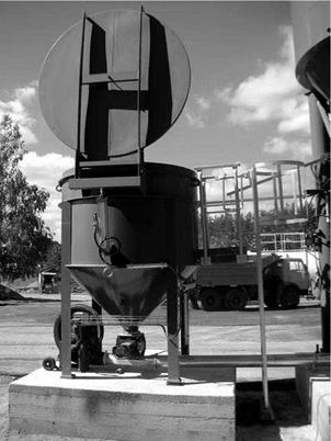
Modern asphalt plants are equipped with integrated silos—delivering and weighing systems mostly designed for granulated or pelletized stabilizers. These stabilizers are stored in silos and then transferred to the scales, proportioned by weight or by volume and blown by compressed air into the pugmill (Figure 9.7). In older plants,

image85

FIGURE 9.7 A system for batching granulated fibers into mixing plants. The photo­graph shows an open silo for granulates ready for loading. (Photo courtesy of Bartosz Wojczakowski.)

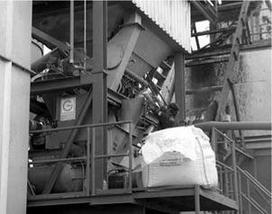
more or less sophisticated batching methods (i. e., proportioning by weight or by volume) are applied to weigh out or measure out a batch of granulated or loose fibers directly into the pugmill (Figure 9.8).

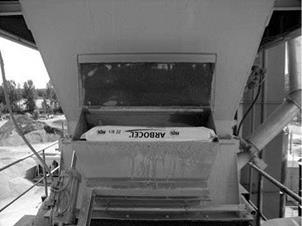
Automatic batching devices for nongranulated (loose fibers) are rare. Bags of loose fibers are emptied through a special charging box into the pugmill (Figure 9.9) or directly through an opening in the upper part of the pugmill’s cover.

image86

FIGURE 9.8 Manual proportioning control of a granulated stabilizer directly into the pug­mill. (Photo courtesy of Bartosz Wojczakowski.)

image87

FIGURE 9.9 Manual charging box with a motor-driven chute. (Photo courtesy of Bartosz Wojczakowski.)

When there are no bins for stabilizer, an effective solution may be the direct delivery of granulated cellulose fibers from a tanker into the pugmill.

Production of SMA in a Drum-Mix Plant

There are two types of drum-mix plants: parallel-flow drum-mix plants and counter-flow drum-mix plants (conventional and double barrel). In drum-mix plants, cool aggregate is delivered from cold-feed bins to a dryer-mixer and then into a silo through a slat conveyor. The mixture gradation control is exercised
through establishing suitable proportions of individual aggregate fractions in cold-feed bins and the rate of aggregate supplied by the feeder belt. The conveyor is equipped with a weight and speed-control system that enables control over the coating plant’s throughput in tons per hour. The general categories of drum-mix plants depend on the flow direction of the aggregate relative to the hot air move­ment from the burner. In parallel-flow drum-mix plants, the aggregate and hot air move in the same direction, while in counter-flow drum-mix plants, they move in opposite directions.

In classic parallel-flow drum-mix plants, the asphalt binder is delivered to a dryer- mixer and injected on the aggregate tumbling inside, which poses a risk of direct contact between the binder and exhaust gases from the dryer’s burner. That is why various solutions have been adopted that place the binder batching point away from the burner and the aggregate drying zone.

In counter-flow drum-mix plants, the aggregate moves in the direction opposite to the movement of exhaust gases. Many precautionary design measures have been built in and are supposed to provide a significant reduction in emissions, a reduction in the exhaust gas temperature, and protection of the binder against overheating. A lengthened part of the drum where mixing takes place, an extra coater, and an embedded burner are a few examples of these solutions. In counter-flow drum-mix plants of the double-barrel type, the aggregate is dried in an inner drum, then dis­charged into the surrounding outer drum, where it is mixed with binder while being protected from the burner’s high temperature. The final asphalt mix is transported to a storage silo with a conveying device.

The SMA aggregate mix contains more than 70% m/m coarse particles, which means that a substantially higher amount of energy is needed to dry and heat them than when manufacturing asphaltic concrete. Furthermore, it may be neces­sary to reduce the output of the coating plant and to extend the veil of aggregate flowing through the dryer-mixer per time unit to obtain the proper aggregate temperature.

Adding a loose fiber stabilizer represents a severe handicap from a produc­tion control standpoint; the location of batching should be chosen carefully so that the loose stabilizer cannot be captured by hot exhaust gases. However, the application of granulated fibers does not present major problems, provided that the point of their addition into the mix is properly determined. Adding granulate to the drum behind the burner (parallel-flow or conventional counter-flow) or to the outer drum before adding binder (counter-flow double-barrel system) is the rule.

Other patterns of Batching constituents in a Batch plant

The KGO-III (Viman et al., 2004) method has been experimentally applied in Sweden since 2002. It consists of changing the order of batching and mixing the constituents in a batch plant. The suggested KGO-III mixing order is as follows:

FIGuRE 9.5 One sequence of batching SMA constituents into a pugmill using a loose form of stabilizer. Notice that the times depend on the type of pugmill. (From Graf, K., Splittmastixasphalt – Anwendung und Bewahrung. Rettenmaier Seminar eSeMA’06. Zakopane [Poland], 2006. With permission.)

Подпись: Coarse and fine aggregates Added filler Stabilizer (loose fibers) Binder Wet mixing Discharging
Other patterns of Batching constituents in a Batch plant
Подпись: 50
Other patterns of Batching constituents in a Batch plant
Подпись: 10 s
Подпись: 10
Подпись: 60
Подпись: 20 Подпись: 70

FIGURE 9.6 Another sequence of batching SMA constituents into a pugmill using a loose form of stabilizer. Notice that the times depend on the type of pugmill. (From Schunemann, M., Faserqualitat. Eine wesentliche Voraussetzung zum Herstellen von qualitatsgerechten Asphaltbefestigungen. Rettenmaier Seminar eSeMA’07, Zakopane [Poland], 2007.)

• Stage 1—mixing binder with an aggregate larger than 4 mm

• Stage 2—adding filler only to dissolve it in the mixture

• Stage 3—adding fine fractions (0.063-4 mm)

Changing the order of batching and mixing are aimed at achieving a thicker binder film on the coarse aggregate. As we know, the smallest grains of aggregate are the first to be coated with binder, in a way capturing the binder and interfer­ing with the creation of thick binder films on the coarse aggregate. Therefore the first stage of the KGO-III approach is intended to coat the bigger grains before the smaller ones.

According to Viman et al. (2004), by employing this approach, about 0.5% less binder may be used in comparison with a typical mixture. It has also been shown that the production temperature of the mixture can be reduced by approxi­mately 30°C. Thus not only can the manufacturer benefit from savings in binder and energy costs, but the process is also favorable for the environment due to lower air pollution (e. g., less odors, fumes, and heat). Six different plants and manufacturers have produced in total 500,000 tons of the mixture according to KGO-III since 1998.

Mixing SMA with a Loose Stabilizer

When incorporating a loose stabilizer, which is usually packed in shrink-wrapped bags, extra time is needed for dry mixing the stabilizer with aggregate. A bag of stabilizer is thrown into the pugmill when the filler is being batched, and then an extra period (about 3 seconds) of dry mixing the fibers with the aggregate follows. Because of this, they are released from the bag and evenly distributed in the mixture. The binder is batched onto the dispersed fibers and aggregates, and additional wet stage mixing time follows. Again, one should to remember that too long a dry mix­ing time could destroy loose fibers.

Figure 9.5 depicts one sequence of the batching of SMA constituents into the pugmill with the use of a loose stabilizer. An example of another batching sequence is shown in Figure 9.6.

The NAPA SMA Guidelines QIS 122 recommend increasing the dry mixing time by 5-15 seconds in comparison with other mixtures without stabilizers. The wet mixing time should be increased by a minimum of 5 seconds when cellulose fibers are used and by not more than 5 seconds when mineral fibers are used.

Mixing SMA with a Granulated Stabilizer

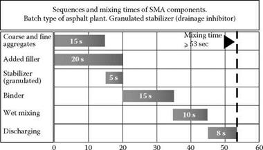
There is a widespread opinion among a large body of practitioners in the field of SMA production that, after all, the sequence of mixing should vary, depending on the kind of stabilizer. In the case of a granulated stabilizer, this is typically batched with the filler and then mixed with the aggregate without any special extra time for dry mixing (Figure 9.3). The extension of mixing time comes after the binder injec­tion into the pugmill, where an additional 10 seconds of wet mixing time is provided (Graf, 2006). In Figure 9.4, another approach to the mixing sequences of granulated stabilizer is shown.

Although some claim that the use of granulated stabilizers does not involve the extension of the dry mixing time, we might—depending on job site results (i. e., fat spots)—be faced with the necessity of such an action to ensure that the granulate has been fully disintegrated.

FIGURE 9.3 The batching sequence of SMA mixture constituents into a pugmill with the use of a granulated cellulose fiber stabilizer. Notice that time depends on the type of pugmill. (From Graf, K., Splittmastixasphalt – Anwendung und Bewahrung. Rettenmaier Seminar eSeMA’06. Zakopane [Poland], 2006. With permission.)

image84

Seconds

FIGURE 9.4 Batching sequence of SMA mixture constituents into a pugmill with the use of a granulated cellulose fiber stabilizer. Notice that time depends on the type of pugmill. (From Schunemann, M., Faserqualitat. Eine wesentliche Voraussetzung zum Herstellen von qualitatsgerechten Asphaltbefestigungen. Rettenmaier Seminar eSeMA’07, Zakopane [Poland], 2007.)

Sequence of Mixing Constituents in a Batch Asphalt Plant

Establishing the sequence of putting materials into the pugmill is chiefly aimed at securing the final homogeneity of a mixture. Mixing constituents consists of the fol­lowing two stages:

• Dry mixing—this starts the moment the aggregate is deposited into the pugmill, and it ends the moment the binder batching starts.

• Wet mixing—this starts the moment the binder batching begins, and it ends the moment the mixture is discharged into a trolley delivering hot material to a silo (the pugmill’s opening).

With regards to the aforementioned stages of mixing, the following universal principles are well-known: [57]

image82,image83

0 10 20 30 40 50 60

Seconds

FIGURE 9.2 The batching sequence in a batch-type asphalt plant according to German DAV handbook. (From Druschner, L. and Schafer, V., Splittmastixasphalt. DAV Leitfaden. Deutscher Asphaltverband, 2000. With permission.)

According to the German DAV handbook [Druschner and Schaffer, 2000], the batching sequence does not depend on the kind of stabilizer. There is an assumption in the DAV handbook that the total mixing time of a cycle should be longer than 53 seconds and consist of the actions shown in Figure 9.2. However, depending on the form of stabilizer (loose fibers or granules), various batching patterns have been cited in other publications, including German ones (Graf, 2006; Schunemann, 2007). These cases are discussed in Sections 9.3.3.1 and 9.3.3.2.

Aside from the universal procedure according to the DAV handbook, there are various batching patterns, depending on the form of stabilizer (loose or granulated fibers), established and practiced by many producers of SMA mixtures.

Mixing: Basic Information

Mixing the components of a bituminous mixture, proportioned by weight from hot – bins, in a batch asphalt plant takes place in a pugmill. Contemporary batch plants have pugmills of various sizes, usually from 1 ton to 8 tons. Despite the different sizes of pugmills and the resulting output of the plants, mixing time, by and large, remains at the same level for all plants (USACE Handbook, 2000). Determining the suitable amounts of materials to batch given the pugmill’s volume is quite a significant step

TABLE 9.1

Recommended Maximum Production Temperatures of an SMA Mixture for example binders according to various Regulations

Mixing: Basic Information Подпись: Germany ZTV Asphalt-StB 07 (Table 5) <190 <180
Подпись: EN 13108-5:2006 (Table 16) <190 <180 <170
Mixing: Basic Information
Подпись: <180 (PMB 25/55-55)
Mixing: Basic Information
Подпись: <190 (PMB 45/80-x)
Mixing: Basic Information

Maximum Mixture Temperature in Asphalt Plant (°С)

Note: PMB = Polymer modified binder.

and is one of the decisive actions undertaken during the plant’s calibration. The quantity of material intended for mixing in one cycle may neither be too large nor too small in comparison with the pugmill’s volume. In the case of an excessive charge of material, the mixing will be ineffective; the mixture will remain partially unmixed and the stabilizer will not be distributed throughout the mixture. An insufficient amount of material in the pugmill will result in throwing the mixture out of the mixing chamber instead of mixing it properly, an acceleration of the binder-aging process and, again, the potential of destroying the stabilizer.

In a drum-mix plant, components are continually delivered into a constantly mix­ing drum. Thus the control of the constituents’ proportions is exercised through the adjustment of the batching rate. The mixing time depends on the shifting rate of materials inside the drum, which can be affected by a variety of factors such as the length of the drum and the angle of the drum.