Category PLUMBER’S AND. PIPE FITTER’S. CALCULATIONS MANUAL

VENT SYSTEM CALCULATIONS

T

Подпись:he calculations of vent systems are not very difficult to understand. There are sizing tables that you can use to compute pipe sizes. Plumbers need to understand the types of vents and master plumbers must be able to assign pipe sizes to them. The task is important, but not really very difficult for experienced plumbers. In many cases, engineers and architects are the ones who design plumbing systems. This is okay. But, it is not always the case. Hav­ing the ability to size a vent system is something that is basically a requirement for a master plumber’s license. Of course, there are many types of plumbing vents. We can talk about dry vents, wet vents, branch vents, yoke vents, and lots of other types of vents. Before we get into the sizing of vents, I want to identify typical types of plumbing vents.

This may be old news to you. If it is, skip past the section and jump right into the sizing information. But, if you are not versed in the full arrangement of vents, you might enjoy the illustrations that I will provide to indicate the basic ingredients of various types of vents.

RISER DRAWINGS

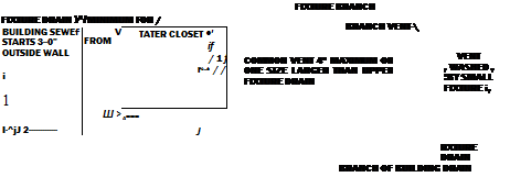
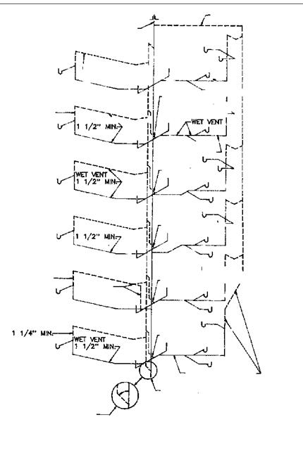
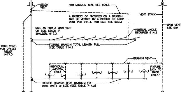
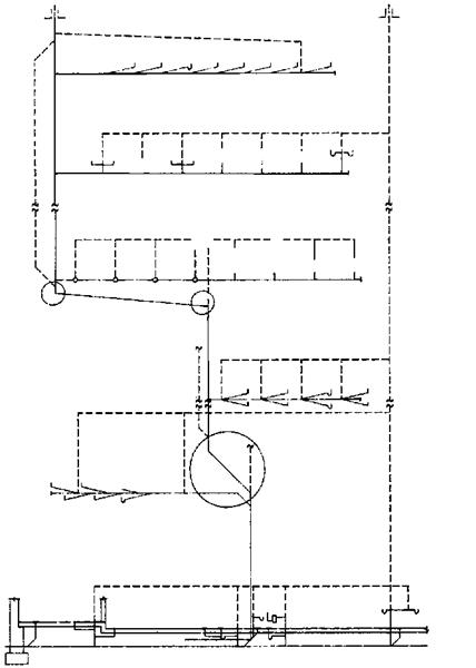
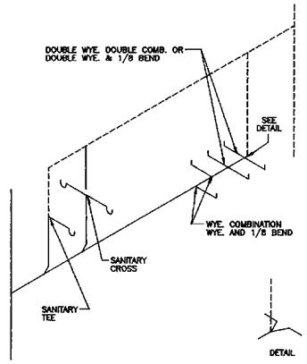
Riser drawings are used when figuring out drainage systems, just as they are used with vent systems. I want to give you some sample riser diagrams to look over. The drawings will show you what your drawings might look like. Drains are drawn with solid lines, while vents are indicated by broken lines.

RISER DRAWINGS

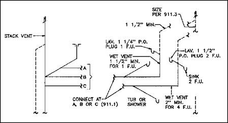
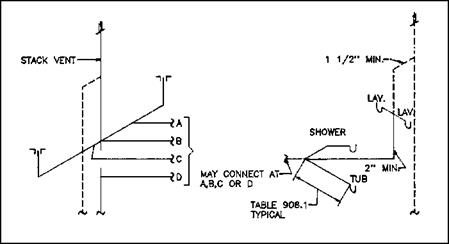
FIGURE 4.26 ■ Wet venting top floor single bath group. (Courtesy of Standard Plumbing Code)

RISER DRAWINGS

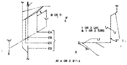
FIGURE 4.27 ■ Wet venting top floor double bath back to back. (Courtesy of Standard Plumbing Code)

RISER DRAWINGS
RISER DRAWINGS

OR


SHOWERS


M N


RISER DRAWINGS
RISER DRAWINGS
RISER DRAWINGS

RISER DRAWINGS

RISER DRAWINGS

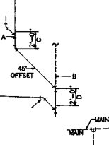
FIGURE 4.28 ■ Wet venting lower floors on multistory buildings. (Courtesy of Standard Plumbing Code)

RISER DRAWINGS

RELIEF VENTS A & В MAY CONNECT TO MAIN—„„

VENT ABOVE FIXTURES ON FLOOR ABOVE

-T—I


RELIEF VENTS REQUIRED-
914.1


SEE 715 UNLESS SIZED FOR A BUILDING DRAIN


RISER DRAWINGS
RISER DRAWINGS

FIGURE 4.29 ■ Riser diagram. (Courtesy of Standard Plumbing Code)


Подпись: DRAIN-AND-SEWER CALCULATIONS

RISER DRAWINGSRISER DRAWINGSRISER DRAWINGS

RISER DRAWINGS

4" MIN.


STACK VENT


i-1 1/4" MIN. I MAN VENT—”j


RISER DRAWINGS

1 1/2" MIN;


WET VENT 1 II


RISER DRAWINGS

REQUIRED VENT


‘klT U~i


REQUIRED VEfJT


WET VENT


1 1/4" MIN;


VENT NOT REQ


RISER DRAWINGS
RISER DRAWINGS
RISER DRAWINGS
RISER DRAWINGS

RISER DRAWINGS

RISER DRAWINGS

FIGURE 4.30 ■ Multistory wet venting. (Courtesy of Standard Plumbing Code)

RISER DRAWINGS

FIGURE 4.31 ■ Riser diagram. (Courtesy of Standard Plumbing Code)


Подпись: DRAIN-AND-SEWER CALCULATIONS

Q

SO


”I

о


Подпись: PLUMBER’S AND PIPE FITTER’S CALCULATIONS MANUAL

YOKE VENT
REQUIRED
SECTIONS
715.4 &
917.3

45’ MAX.
FROM
VERTICAL
TO PREVENT
FOULING


-SIZE FOR
NUMBER OF
FIXTURE UNITS
ABOVE OFFSET

FOR

OMISSION ________

SEE SEC. T
715.5


BLOWOUT FIXTURES REQUIRE INDIVIDUAL VENTS,7 BATTERY VENTING NOT PERMITTED. /


SIZE OF EACH SECTION OF VENT BASED ON FIXTURE UNIT LOAD.


RELIEF VENT REQUIRED, SEE 715.4
<St 917.3 {SIZE FOR MAIN VENT)

FOR OMISSION SEE
SEC. 715.5

H—-NO HORIZONTAL BRANCH CONNECTION 715.4


OFFSET OF MORE THAN 45* FROM VERTICAL SIZE AS FOR A BUILDING DRAIN. 715.4


-NO HORIZONTAL-1 BRANCH CONNECTION 715.4


SIZE FOR OFFSET AND TOTAL FIXTURE UNITS ON STACK


RISER DRAWINGS

4 /L


VENT FIXTURES BACK TO BACK IN BATTERY, 914.3


FIGURE 4.32 ■ Riser diagram. (Courtesy of Standard Plumbing Code)


RISER DRAWINGSRISER DRAWINGSRISER DRAWINGSRISER DRAWINGS

RISER DRAWINGS

VENT TERMINAL SEC. 904.2 AND 905


BATTERY WITH LOOP VENT


SIXTH FLOOR


RISER DRAWINGS

o4-o o4-o LrTJ


FIFTH FLOOR


4


RISER DRAWINGS

——


FOURTH FLOOR


RISER DRAWINGS
RISER DRAWINGS

BACK TO BACK IN BATTERY


THIRD FLOOR


RISER DRAWINGS
RISER DRAWINGS

SECOND FLOOR


RISER DRAWINGS

RISER DRAWINGS

RISER DRAWINGS

FIGURE 4.33 ■ Drainage waste and vent reference diagram. (Courtesy of Standard Plumbing Code)

RISER DRAWINGS

FIGURE 4.34 ■ Fixtures back-to-back in battery. (Courtesy of Standard Plumbing Code)

FITTINGS

As you are drawing your riser diagrams, you should keep in mind the fittings that will be used for changes in direction. There are three ways to change di­rection. Your pipe can go from horizontal to vertical, from vertical to hori­zontal, or from horizontal to horizontal. The fittings used in a drainage sys­tem to make these changes are regulated by the rules of the local plumbing code. As a rule-of-thumb, you can refer to Figure 4.25 for the common use and acceptance of fittings when changing directions. Again, always confirm local code requirements before committing to a job.

Type

of

fitting

Horizontal

to

vertical

Vertical

to

horizontal

Horizontal

to

horizontal

Sixteenth bend

yes

yes

yes

Eighth bend

yes

yes

yes

Sixth bend

yes

yes

yes

Quarter bend

yes

no

no

Short sweep

yes

yes

no

Long sweep

yes

yes

yes

Sanitary tee

yes

no

no

Wye

yes

yes

yes

Combination wye

yes

yes

yes

and eighth bend

SIZING TALL STACKS

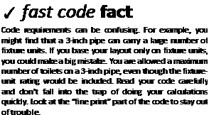
Sizing tall stacks will require you to use different sizing tables. A tall stack is one that has more than three branch intervals. Figure 4.19 and Figure 4.20 will show you the basics needed to size tall stacks for two different codes. There are differences in the number of fixture units allowed between the two codes. Since the tables are so much like others we have used, I won’t go into a lot of detail on them.

SUPPORTS

SIZING TALL STACKS

supports for drainage systems are needed. The distance between supports varies with the type of pipe being used and the local code that you are work­ing with. There are also differences between vertical and horizontal piping when you are designing your support placement. We could talk about this, but it would be faster and easier to just give you some reference tables to use when you need them. Figure 4.21 is for horizontal pipe with one code and

FIGURE 4.20 ■ Stack-sizing tall stacks in Zone Three (stacks with more than three branch intervals). (Courtesy of McGraw-Hill)

Maximum distance of supports (ft)


ABS

4

Cast iron

At

Galvanized (1 in and larger)

12

Galvanized (% in and smaller)

10

PVC

4

Copper (2 in and larger)

10

Copper (lVfc in and smaller)

6

Support material

Подпись: *Cast-iron pipe must be supported at each joint, but supports may not be more than 10 ft apart.

FIGURE 4.21 ■ Horizontal pipe-support intervals in Zone One. (Courtesy of McGraw-Hill)

Подпись: ✓ fast code fact Horizontal drainage pipe is required, normally, to be supported at a maximum interval of four feet.

Подпись: Maximum distance of supports (ft)

Figure 4.22 is for the same situation, but with a different code. Figure 4.23 deals with vertical pipes for one code, and Figure 4.24 shows vertical support requirements for a different code.

Type of drainage pipe

ABS

4

Cast iron

At

Galvanized (1 in and larger)

12

PVC

4

Copper (2 in and larger)

10

Copper (IV2 and smaller)

6

FIGURE 4.22 ■ Horizontal pipe-support intervals in Zone Two. (Courtesy of McGraw-Hill)

Type of drainage pipe Maximum distance of supports*


4 ft

At each story

At least every other story

At each storyt

Not mentioned

Not mentioned


Lead pipe

Cast iron

Galvanized

Copper

PVC

ABS


*A11 stacks must be supported at their bases. tSupport intervals may not exceed 10 ft.


Type of drainage pipe Maximum distance of supports (ft)*


Lead pipe Cast iron Galvanized

Copper (lVi in and smaller) Copper (IV2 and larger) PVC (ІУ2 in and smaller) PVC (2 in and larger)

ABS (ІУ2 in and smaller) ABS (2 in and larger)


4

At each storyt At each storyt 4

At each story 4

At each story 4

At each story


*A11 stacks must be supported at their bases. tSupport intervals may not exceed 15 ft. ^Support intervals may not exceed 30 ft.


FIGURE 4.24 ■ Vertical pipe-support intervals in Zone Two. [Courtesy of McGraw-Hill)

A HORIZONTAL BRANCH

Подпись: *Table does not represent branches of the building drain, and other restrictions apply under battery-venting conditions. tNot more than two toilets may be connected to a single З-in horizontal branch. Any branch connecting with a toilet must have a minimum diameter of 3 in.

Let’s talk about how you can size a horizontal branch. Bet you can guess that we are going to use a sizing table. Hey, they’re easy, fast, and accu­rate, so why not use them? Look at Figure 4.16. This table shows you the maximum number of fixture units that may be placed on a single horizon­tal branch of a given size. If you look closely, you will see, once again, that not more than two toilets can be installed on a single 3-inch pipe that is in­stalled horizontally. It should also be noted that the table does not repre­sent the branches of a building drain and that other restrictions may apply if doing a series of battery venting.

Pipe size (in)

Maximum no. of fixture units

1 Vi

1

V/2

2

2

6

3

20t

4

160

6

620

A HORIZONTAL BRANCH

FIGURE 4.17 ■ Stack-sizing table for Zone Three. (Courtesy of McGraw-Hill)

STACK SIZING

A HORIZONTAL BRANCH

Stack sizing requires you to know the number of fixture units that will dis­charge into the stack from a single branch and the total number of fixture units that will be allowed on the stack. So, let’s say that you have a stack with two branches. There is a bathroom group on each branch, and those two bathroom groups are all that will discharge into the stack. What size pipe is the smallest allowable for use as the stack? To figure this, use the table in Fig­ure 4.17. So that you don’t have refer back to the fixture-rate table, I will tell you that each bathroom group is rated for six fixture units. Well, we have two toilets, so we know the pipe size must be at least three inches in diameter. With 6 fixture units per branch we might get by with a 2-inch pipe if there were no toilets involved. But, toilets are involved and the total load on the stack will be 12 fixture units, so we have to go with a 3-inch pipe. For infor­mational purposes, check out the sizing chart in Figure 4.18. Notice the dif­ference in the number of fixture units allowed on a branch with Figure 4.18 when compared to Figure 4.17. There are two codes at work in these exam­ples, and you can see that the difference for 4-inch pipe on a per-branch ba­sis is 70 additional fixture units with one of the codes.

FIGURE 4.18 ■ Stack-sizing table for Zone Two. (Courtesy of McGraw-Hill)

Fixture-unit discharge Total fixture

Pipe size (in) on stack from a branch units allowed on stack

І’Л 2 8

2 6 24

3 16* 60*

4 90 500


*N0 more than two toilets may be placed on a З-in branch, and no more than six toilets may be connected to a З-in stack.


FIGURE 4.19 ■ Stack-sizing tall stacks in Zone Two (stacks with more than three branch intervals). (Courtesy of McGraw-Hill)

FIXTURE-UNIT TABLES

Fixture-unit tables are often used when sizing drains and sewers. The table in Figure 4.1 is an example of a table that expresses the maximum number of fix­ture units allowed on pipes of various sizes and with various amounts of fall. Before we go on, look at the category for 3-inch pipe, at a V4-inch per foot fall. It says that you are allowed 27 drainage fixture units. But, notice the lit­tle number 2 next to the number of fixture units. That number indicates a note or exception. When you look at the bottom of the table, you will see that the note tells you that not more than two water closets can be carried on a 3-inch pipe. There are exceptions, but if you stick with this rule, you can’t go wrong. This is one of the tables that I was telling you about earlier.

Diameter of pipe

Fall in

inches per foot

(in)

‘/ні

%

‘/4

‘/2

2

21

26

2 Vi

24

31

3

202

272

362

4

180

216

250

5

390

480

575

6

700

840

1000

8

1400

1600

1920

2300

10

2500

2900

3500

4200

12

3900

4600

5600

6700

15

7000

8300

10,000

12,000

‘Includes branches of the building drain. The mini­mum size of any building drain serving a water closet shall be 3".

“Not over two water closets.

FIGURE 4.1 ■ Allowable fixture-unit loads. (Courtesy of McGraw-Hill)

FIXTURE-UNIT TABLES

Fixture-unit

value as load Minimum size

factors of trap (ini


Fixture type


Bathroom group consisting of water closet, lavatory, and bathtub or shower

Bathtub (with or without overhead shower) or whirlpool attachments Bidet

Combination sink and tray

Combination sink and tray with food disposal unit

Dental unit or cuspidor

Dental lavatory

Drinking fountain

Dishwashing machine domestic

Floor drains

Kitchen sink, domestic

Kitchen sink, domestic with food waste grinder and/or dishwasher Lavatory Lavatory

Lavatory, barber, beauty parlor

Lavatory, surgeon’s

Laundry tray (1 or 2 compartments)

Shower stall, domestic Showers (group) per head Sinks Surgeon’s

Flushing rim (with valve)

Service (trap standard)

Service (P trap)

Pot, scullery, etc.

Urinal, pedestal, siphon jet, blowout Urinal, wall lip Urinal, washout Washing machines (commercial)

Washing machine (residential)

Wash sink (circular or multiple) each set of faucets Water closet, flushometer tank, public or private Water closet, private installation Water closet, public installation


6

2

lVi

2

Nominal l’A

3

1 Vi

4

Separate traps 1 Vi

1

1%

1

l’A

‘A

1

2

lVi

1

2

2

l’A

3

lVi

1

Small P. O. l’A

2

Large P. O. l’A

2

l’A

2

l’A

2

l’A

2

2

3

3

llA

8

3

3

3

2

2

4

l’A

8

Note 6

4

Note 6

4

Note 6

3

2

2

Nominal 1 Vi

3

Note 6

4

Note 6

6

Note 6


FIGURE 4.2 ■ Fixture-unit ratings. (Courtesy of McGraw-Hill)


The information in Figure 4.2 is representative of what you might find in your local codebook. This is the type of table that assigns specific ratings for fixture units on given fixtures. In cases where a known fixture is not listed, an­other type of table, like the one in Figure 4.3, is used to assign ratings for fix­ture units. Before we get too many tables in front of us, let’s go over the three that you’ve just been introduced to.


The table in Figure 4.1 is easy enough to understand. If you find the size of the pipe you are working with, you can quickly ascertain the number of fix­ture units allowed on the pipe at a given grade. When you know the number of fixture units and the grade of the pipe, you can tell what size pipe is suit­able. For example, a 4-inch sewer that is installed with a grade of one-quarter of an inch per foot can handle up to 216 fixture units, and that’s a lot of drainage. Upgrading to a 6-inch pipe with the same grade will allow you to load the pipe with 840 drainage fixture units. That’s all there is to that table.

Подпись:FIXTURE-UNIT TABLESПодпись: When dealing with a residential property, a 4-inch sewer will handle all of the fixture units that could reasonably be installed in a home. Avoid installing a 3-inch sewer. Give homeowners the option of expansion by spending a little more money for the larger sewer.The listings in Figure 4.2 are compre­hensive and easy to understand. For ex­ample, a residential toilet is assigned a fixture-unit rating of four. A typical lava­tory has a rating of one fixture unit. Do­mestic shower stalls are rated for two fix­ture units. If you add this up, you find that the three normal bathroom fixtures total a rating of seven fixture units. How­ever, if you look at the top of the list, you will see that a bathroom group that con­sists of a toilet, lavatory, and bathtub or

Подпись: been there done that As a young plumber, I believed that the code was the code. At the time, I worked in a metro area where there were numerous jurisdictions. Even being close together, I found out the hard way that not every city and county used the same code. Always check the local code in the area where you will be working to stay out of trouble. shower has a rating of 6 fixture units. Wait a minute, that’s one fixture unit less than the individual ratings for the same fixtures. What gives? In this case, as­suming that all of the fixtures were being placed in the same bathroom, you could use the lower of the two ratings. Why? Because it is assumed that not all of the fixtures will be being used simul­taneously if they are confined to a single room. The use of a table, like the one in Figure 4.2, makes sizing drains a lot easier.

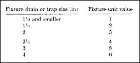
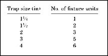
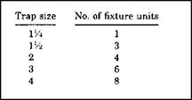
There may be times when the fixture that you are seeking a rating for will not be listed on a fixture-unit table. If this is the case, you can use a table, like the one in Figure 4.3, to assign a rating for fixture units. For example, a fixture with a 2-inch drain that is not otherwise listed would be

FIXTURE-UNIT TABLES

FIGURE 4.3 ■ Allowable fixture units based on trap size. (Courtesy of McGraw-Hill)


Maximum no. of fixture units that may
be connected to:


Diameter

of

pipe"

(in)

Any

horizontal fixture branch14

One stack of 3 stories or 3

intervals

maximum

More than 3 stories in height

Total for stack

Total at one story or branch interval

VA

1

2

2

1

Г/І

3

4

8

2

2

6

10

24

6

2 Vi

12

20

42

9

3

20“

ЗО"

60”

16"

4

160

240

500

90

5

360

540

1100

200

6

620

960

1900

350

8

1400

2200

3600

600

10

2500

3800

5600

1000

12

3900

6000

8400

1500

15

7000

‘Does not include branches of the building drain.

"Not over two water closets.

’Not over six water closets.

4509f less for battery vented fixture branches, no size reduction permitted for battery vented branches throughout the entire branch length.

”The minimum size of any branch or stack serving a water closet shall be


3".


FIGURE 4.4 ■ Maximum fixture units. (Courtesy of McGraw-Hill)


rated for three fixture units. A 4-inch drain would carry a rating of six fixture units. Pretty simple stuff, huh?

Some tables, like the one in Figure 4.4, deal with different piping arrange­ments. For example, the table in Figure 4.4 allows you to rate any horizontal branch stacks for multiple-story buildings and branch intervals. Notice that


Diameter of vent

Number of wet-vented fixtures stacks (in)


1 or 2 bathtubs or showers 2

3 to 5 bathtubs or showers 2Vi

6 to 9 bathtubs or showers 3

10 to 16 bathtubs or showers 4


FIGURE 4.5 ■ Vent sizing table. (Courtesy of McGraw-Hill)


FIXTURE-UNIT TABLES

FIGURE 4.6 ■ Trap-to-vent distances. (Courtesy of McGraw-Hill)

several of the ratings are marked with exclusions. This is the type of detailed information that you must be on the lookout for.

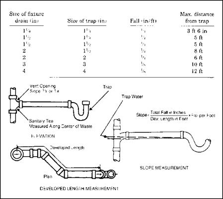
Suppose you are concerned about sizing a vent stack that will accommo­date wet-vented fixtures? No problem, just use a table like the one in Figure 4.5. This table is so simple that it needs no explanation. Now, what if you need to know how long a trap arm may be? Refer to a table like the one in Fig­ure 4.6 for the answers to your questions. Depending on trap size, the size of the fixture drain, and the amount of fall on the trap arm, you can choose a maximum length quickly.

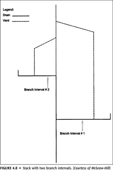
Take a look at Figure 4.7. It is a riser diagram of a branch-interval de­tail. It is sometimes necessary to break a drainage system down into branch intervals for sizing. If you need to do this, you can refer to this drawing for a clear understanding of where branch intervals break and what they are. Figure 4.8 shows a stack with two branch intervals. To size a system like this, you must apply your sizing techniques to each individual branch and to the stack.
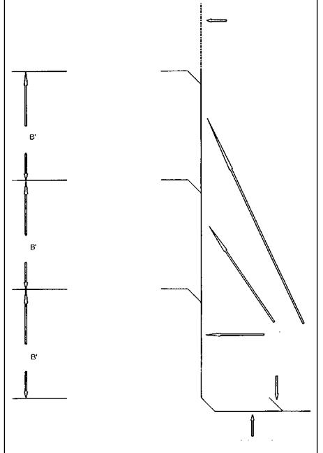
Vent Through Roof


3rd Branch Interval


2nd Branch Interval


1st Branch Interval


Soil Stack


Cleanout


Building Drain


FIGURE 4.7 ■ Branch-interval detail. (Courtesy of McGraw-Hill)


FIXTURE-UNIT TABLES

FIXTURE-UNIT TABLES

TRAP SIZING

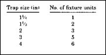
Trap sizing is a simple procedure. All you need is some basic information and a sizing table. If you know your trap size, you can determine the fixture-unit load that is allowable. When you know the number of fixture units that will be placed on a trap, you can decide on a trap size. There’s not much to it. Fig­ures 4.9, 4.10, and 4.11 show limits for fixture units on traps in the three main plumbing codes. If you notice, two of the codes have the same ratings, but one is more liberal than the other two. Remember to use your local code when doing actual sizing.

FIXTURE-UNIT TABLES

FIGURE 4.9 ■ Zone Two’s fixture – unit requirements on trap sizes. (Courtesy of McGraw-Hill)

FIXTURE-UNIT TABLES

FIGURE 4.10 ■ Zone Three’s fixture-unit requirements on trap sizes. (Courtesy of McGraw-Hill)

FIXTURE-UNIT TABLES

FIGURE 4.11 ■ Zone One’s fixture – unit requirements on trap sizes. (Courtesy of McGraw-Hill)

THE RIGHT PITCH

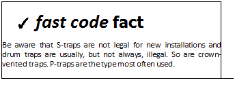
Подпись: ✓ fast code fact Be aware that S-traps are not legal for new installations and drum traps are usually, but not always, illegal. So are crown-vented traps. P-traps are the type most often used. Подпись: ► sensible shortcutПодпись:

Подпись: Pipe diameter (in) FIXTURE-UNIT TABLES Подпись: Having too much grade on a pipe can be as bad as not having enough. If a drain pitches downward too hard, liquids will leave the pipe and suspend solids in the drain that could cause a stoppage. Maintain an even grade, usually one-quarter-of- an-inch per foot. FIXTURE-UNIT TABLES

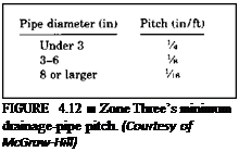
Having the right pitch on a pipe is neces­sary when complying with a plumbing code. The amount of pitch, or grade, on a pipe can affect its allowable length and fixture-unit load. You can use the tables in Figures 4.12, 4.13, and 4.14 as examples of how a local code might put rules in place for you to follow. The tables are easy to understand and use.
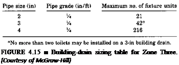
Подпись: FIGURE 4.15 ■ Building-drain sizing table for Zone Three. [Courtesy of McGraw-Hill)
SIZING BUILDING DRAINS

Sizing building drains is simple when you have a sizing table and some basic information. Refer to Figure 4.15 for an example of a sizing table for a build­ing drain. In this example, all pipes are based on a pitch of one-quarter of an inch per foot. A 3-inch pipe can carry up to 42 fixture units, but not more than two toilets. Tables like this one should be available in your local codebook.
DRAIN-AND-SEWER CALCULATIONS

D

oing calculations for drains and sewers is similar, in principle, to what you will use for vents in the next chapter. The process involves fixture units, the developed length of piping, sizing tables, and so forth. Pay­ing attention to details is an important element in designing any type of sys­tem, and this certainly holds true when sizing drains and sewers. Moving too quickly and using the wrong sizing table can cause you a lot of trouble. When work is simplified, it sometimes seems so simple that it is taken too lightly. Don’t make mistakes by not paying attention to footnotes and exclusions when you use sizing tables. If you read the tables carefully and apply them properly, sizing is not difficult.

Подпись:Some plumbers get so accustomed to using sizing tables that they fail to think of code requirements that may make the tables inaccurate if all notes are not observed and followed. For example, let’s say that you are sizing a sewer for a home.

You might do your homework and find that the total number of fixture units is low enough that a 3-inch sewer can be used. This might be the case, but you could be setting yourself up for trouble.

Accuracy in sizing pipes is essential to a job in more than one way. First, you have to draw riser diagrams and size the pipes for code approval. And, you need accurate sizing to price a job for bidding purposes.

Let’s say that you did believe that a home could get by with a 3-inch sewer. Assume that the home was a town­house and that it was one of 300 in a project, where you were bidding the en­tire project. This means that you basically figure maybe four styles of houses

49

and then apply the information to the entire project. The cost difference between 3-inch and 4-inch pipe doesn’t seem like a lot when you are dealing with short runs. But, when you are dealing with 300 runs, even small differ­ences in cost can add up quickly. So, what would happen if you figured a job for 3-inch sewers and wound up having to install 4-inch sewers? You or your employer would lose money, possibly a substantial sum.

Подпись: ► sensible shortcutDRAIN-AND-SEWER CALCULATIONSПодпись: As a rule-of-thumb, don’t plan on putting more than two toilets on a 3-inch drain. There are often conditions that will allow up to three toilets on a 3-inch drain, but I would suggest running a 4-inch pipe for three toilets if you want to keep it simple.When we get further into this chap­ter you will see actual examples of how a mistake might be made when using siz­ing tables for drains and sewers. But, I’d like to point out a quick one now, so that you will keep your eyes open when we get to the sizing tables. okay, it is very likely that the total fixture load for a 3- bathroom townhouse would be low enough to allow the use of a 3-inch sewer. if you were in a hurry, did a quick calculation of fixture units and scanned a sizing table, you might jump right at using 3-inch pipe to keep costs down. This would be a mistake. Why? Be­cause even though a 3-inch pipe could handle the fixture units, most codes limit a 3-inch pipe to serving no more than two water closets in close prox­imity. If the townhouse has three toilets, a 4-inch sewer is likely to be needed.

As a teacher of plumbing courses, I’ve seen a number of experienced plumbers fall for this trap on some of the tests that I’ve created. The plumbers get into a rhythm and fail to think or to see the notes on the sizing charts and distance requirements. It’s bad to miss a question on an exam, but it would be much worse to make the mistake in the real world of plumbing. By catching the plumbers in the classroom, I hope to make them aware of the crossover traps that can be embedded in the plumbing code. There are usually excep­tions, options, and exclusions that can change the meaning of the code in cer­tain situations. The 3-inch sewer is one excellent example of such pitfalls. You do have to pay attention to what you are doing when sizing systems.

TYPES OF SANITARY DRAINS

There are several types of sanitary drains. A building sewer is usually consid­ered to be the main drain for a building that starts outside of the building and

Подпись:extends to a municipal sewer or private sewage-disposal system. Building drains are the primary drains inside of a building. Then there are branch intervals, horizon­tal branches, vertical stacks, and so forth. When you begin sizing a drainage system, you must make sure that you are using the proper sizing procedures for the type of drain or sewer that you are working with.

All types of drains and sewers can be calculated with a method that depends on the ratings of drainage fixture units.

DRAIN-AND-SEWER CALCULATIONSПодпись: ► sensible shortcutПодпись: Use the tables in your codebook to calculate fixture units, load ratings, and pipe sizing. This is fast, easy, and accurate.Fixture-unit ratings are established by lo­cal codes. A probability factor is built into the system. While a direct flow rate or discharge rate cannot be determined from the rating of fixture units, the fix­ture units are accurate enough to allow a sensible system to be designed in compliance with the plumbing code.

THE STANDARD PLUMBING CODE

The Standard Plumbing Code provides a sizing example in their codebook. The Standard Plumbing Code, the BOCA code, and the International Plumb­ing Code have joined together and your local code office may have any vari­ation of these three codes in effect, so check your local codes carefully. A fac­tory is the building chosen for their sizing exercise. The instructions provided in their sizing example and explanations is good. By using the tables provided and the formulas given, you can size the water distribution system for the building with minimal stress.

The responsibility of sizing a large water system may never be placed on your shoulders. Architects and engineers will probably design most of the sys­tems that you install in large buildings. But, it does pay to understand the con­cepts behind sizing a system. Work through the examples I’ve provided above until you are comfortable with the procedure. Once you get the hang of it, sizing a system is not terribly difficult.

SIZING WITH THE UNIFORM PLUMBING CODE

Sizing with data from the Uniform Plumbing Code is not too difficult. Allow me to give you some illustrations that are direct excerpts from the Uniform Plumbing Code. Look at the illustrations and try working through the sizing example that is provided (Fig. 3.1 through Fig. 3.17).

APPENDIX A


Because of the variable conditions encountered, it is impractical to lay down definite detailed rules of procedure for determining the sizes of water supply pipes in an appendix which must necessarily be limited in length. For a more adequate understanding of the problems involved, the reader is referred to Water-Distributing Systems for Buildings, Report BMS 79 of the National Bureau of Standards; and Plumbing Manual, Report BMS 66, also published by the National Bureau of Standards.

The following is a suggested order of procedure for sizing the water supply system.

A 1 Preliminary Information

A 1.1 Obtain the necessary information regarding the minimum daily service pressure in the area where the building is to be located.

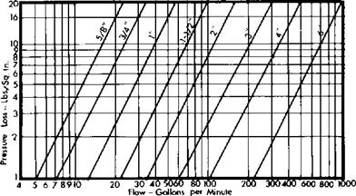
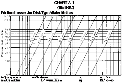
A 1.2 If the building supply is to be metered, obtain information regarding friction loss relative to the rate of flow for meters in the range of sizes likely to be used. Friction-loss data can be obtained from most manufacturers of water meters. Friction losses for disk type meters may be obtained from Chart A-1.

CHART A-1

Friction Losses for Disk Type Water Meters


SIZING WITH THE UNIFORM PLUMBING CODE

SIZING WITH THE UNIFORM PLUMBING CODE

A 1.3 Obtain all available local information regarding the use of different kinds of pipe with respect both to durability and to decrease in capacity with length of service in the particular water supply.

A 2 Demand Load

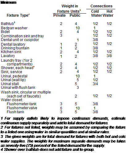
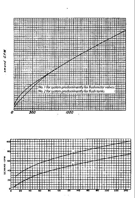
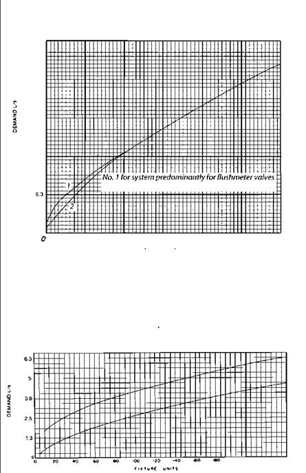
A 2.1 Estimate the supply demand for the building main and the principal branches and risers of the system by totaling the fixture units on each, Table A-2, and then by reading the corresponding ordinate from Chart A-2 or A-З, whichever is applicable.

A 2.2 Estimate continuous supply demands in gallons per minute (liters per second) for lawn sprinklers, air conditioners, etc., and add the sum to the total demand for fixtures. The result is the estimated supply demand of the building supply.

A 3 Permissible Friction Loss

A 3.1 Decide what is the desirable minimum pressure that should be maintained at the highest fixture in the supply system. If the highest group of fixtures contains flushometer valves, the pressure for the group should not be less than fifteen (15) psi (103.4kPa). For flush tank supplies, the available pressure may not be less than eight (8) psi (55.1 kPa).

A 3.2 Determine the elevation of the highest fixture or group of fixtures above the water (street) main. Multiply this difference in elevation by forty-three hundredths (0.43). The result is the loss in static pressure in psi (pounds per square inch) (kPa).


A 3.3 Subtract the sum of loss in static pressure and the pressure to be maintained at the highest fixture from the average minimum daily service pressure. The result will be the pressure available for friction loss in the supply pipes, if no water meter is used. If a meter is to be installed, the friction loss in the meter for the estimated maximum demand should also be subtracted from the service pressure to determine the pressure loss available for friction loss in the supply pipes.

TABLE A-2

Demand Weight of Fixtures in Fixture Units 1


SIZING WITH THE UNIFORM PLUMBING CODE

Diameter of fitting

90°

Stand­

ard

45°

Stand­

ard

Stand­

ard

Coupling

or

Straight

Gate

Globe

Angle

(inches)

Elbow

Elbow

Tee 90Run of Tee Valve

Valve

Valve

Feet

Feet

Feet

Feet

Feet

Feet

Feet

3/8

1

0.6

1.5

0.3

0.2

8

4

1/2

2

1.2

3

0.6

0.4

15

8

3/4

2.5

1.5

4

0.8

0.5

20

12

1

3

1.8

5

0.9

0.6

25

15

1-1/4

4

2.4

6

1.2

0.8

35

18

1-1/2

5

3

7

1.5

1

45

22

2

7

4

10

2

1.3

55

28

2-1/2

8

5

12

2.5

1.6

65

34

3

10

6

15

3

2

80

40

4

14

8

21

4

2.7

125

55

5

17

10

25

5

3.3

140

70

6

20

12

30

6

4

165

80


TABLE A-3

(metric)

Eauivalent Lenath of PiDe for Various Fittinas

90°

U1

0

Coupling

Diameter

Stand-

Stand-

Stand-

or

of fitting

ard

ard

ard

Straight

Gate

Globe

Angle

(inches)

Elbow

Elbow

Tee 90° Run of Tee Valve

Valve

Valve

m

m

m

m

m

m

m

9.5

0.3

0.2

0.5

0.1

0.1

2.4

1.2

12.7

0.6

0.4

0.9

0.2

0.1

4.6

2.4

19.1

0.8

0.5

1.2

0.2

0.2

6.1

3.6

25.4

0.9

0.5

1.5

0.3

0.2

7.6

4.6

31.8

1.2

0.7

1.8

0.4

0.2

10.6

5.5

38.1

1.5

0.9

2.1

0.5

0.3

13.7

6.7

50.8

2.1

1.2

3

0.6

0.4

16.7

8.5

63.5

2.4

1.5

3.6

0.8

0.5

19.8

10.3

76.2

3

1.8

4.6

0.9

0.6

24.3

12.2

101.6

4.3

2.4

6.4

1.2

0.8

38

16.7

127

5.2

3

7.6

1.5

1

42.6

21.3

152.4

6.1

3.6

9.1

1.8

1.2

50.2

24.3


* Allowances based on поп-recessed threaded fittings. Use one-half (1/2) the allowances for recessed threaded fittings or streamline solder fittings.


SIZING WITH THE UNIFORM PLUMBING CODE

A 3.4 Determine the developed length ot pipe from the water (street) main to the highest fixture. If close estimates are desired, compute with the aid of Table A-З the equivalent length of pipe for all fittings in the line from the water (street) main to the highest fixture and add the sum to the developed length. The pressure available for friction loss in pounds per square inch (kPa), divided by the developed lengths of pipe from the water (street) main to the highest fixture, times one hundred (100), will be the average permissible friction loss per one hundred (100) foot (30.4m) length of pipe.

A 4 Size of Building Supply

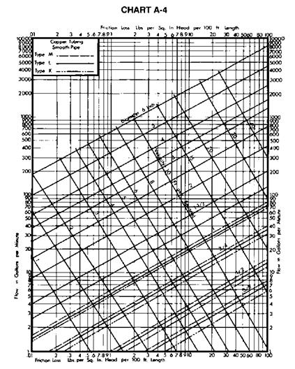
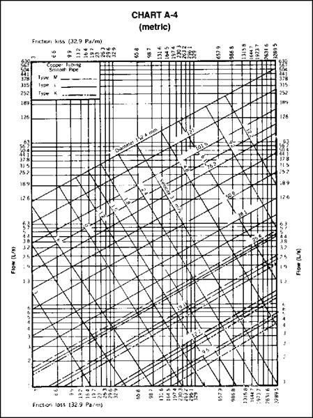
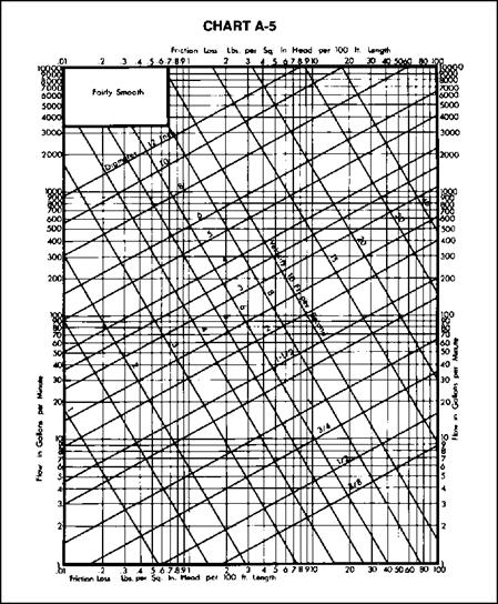
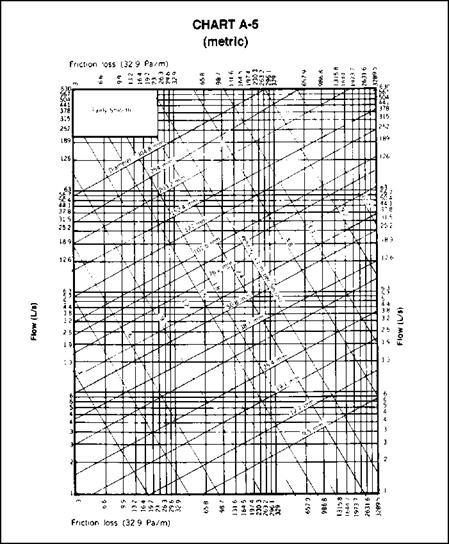
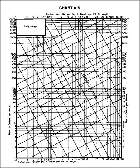
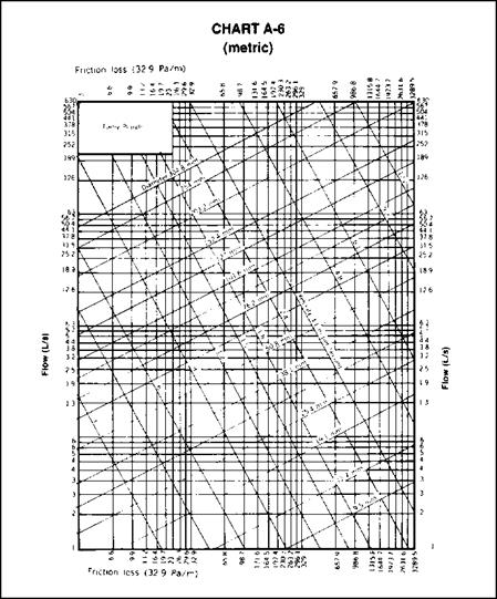
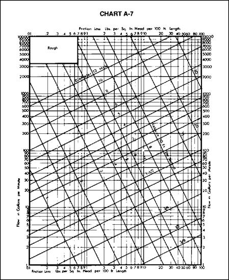
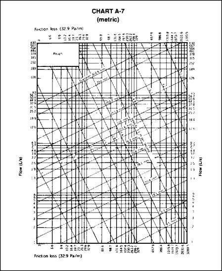
A 4.1 Knowing the permissible friction loss per one hundred (100 feet (30.4 m) of pipe and the total demand, the diameter of the building supply pipe may be obtained from Charts A-4, A-5, A-6, or A-7, whichever is applicable. The diameter of pipe on or next above the coordinate point corresponding to the estimated total demand and the permissible friction loss will be the size needed up to the first branch from the building supply pipe.

A 4.2 If copper tubing or brass pipe is to be used for the supply piping, and if the character of the water is such that only slight changes in the hydraulic characteristics may be expected, Chart A-4 may be used.

A 4.3 Chart A-5 should be used for ferrous pipe with only the most favorable water supply as regards corrosion and caking. If the water is hard or corrosive, Charts A-6 or A-7 will be applicable. For extremely hard water, it will be advisable to make additional allowances for the reduction of capacity of hot water lines in service.

A 5 Size of Principal Branches and Risers

A 5.1 The required size of branches and risers may be obtained in the same manner as the building supply by obtaining the demand load on each branch or riser and using the permissible friction loss computed in Section A 3.

A 5.2 Fixture branches to the building supply, if they are sized for the same permissible friction loss per one hundred (100) feet (30.4 m) of pipe as the branches and risers to the highest level in the building, may lead to inadequate water supply to the upper floor of a building. This may be controlled by: (1) selecting the sizes of pipe for the different branches so that the total friction loss in each lower branch is approximately equal to the total loss in the riser, including both friction loss and loss in static pressure; (2) throttling each such branch by means of a valve until the preceding balance is obtained; (3) increasing the size of the building supply and risers above the minimum required to meet the maximum permissible friction loss.

A 5.3 The size of branches and mains serving flushometer tanks shall be consistent with sizing procedures for flush tank water closets.


A 6 General

A 6.1 Velocities shall not exceed 10 ft/sec or the maximum values given in the appropriate Installation Standard, except as otherwise approved by the Administrative Authority.

A 6.2 If a pressure reducing valve is used in the building supply, the developed length of supply piping and the permissible friction loss should be computed from the building side of the valve.

A 6.3 The allowances in Table A-З for fittings are based on nonrecessed threaded fittings. For recessed threaded fittings and streamlined soldered fittings, one-half (1/2) the allowances given in the table will be ample.

A 7 Example

A 7.1 Assume an office building of four (4) stories and basement; pressure on the building side of the pressure reducing valve of fifty-five (55) psi (379 kPa) (after an allowance for reduced pressure "fall off” at peak demand); an elevation of highest fixture above the pressure reducing valve of forty-five (45) feet (13.7 m); a developed length of pipe from the pressure reducing valve to the most distant fixture of two hundred (200) feet (60.8 m); and fixtures to be installed with flush valves for water closets and stall urinals as follows:


Example


Fixture Units and Estimated Demands


SIZING WITH THE UNIFORM PLUMBING CODE

Water Closets

130

1,300

Urinals

30

150

Shower Heads

12

48

12

12×4 x

3/4 = 36 (2.3 L/s)

Lavatories

130

260

130

130×2 x

3/4 = 195 (12.3 Us)

Service Sinks

27

108

27

27×4 x

3/4 = 81 5.1 Us)

Total

1,866

313 (19.7 L/s)

312

106

(6.7 Us)

Allowing for fifteen (15) psi (103.4 kPa) at the highest fixture under the maximum demand of three hundred and ten (310) gallons per minute (19.6 L/s), the pressure available for friction loss is found by the following:


SIZING WITH THE UNIFORM PLUMBING CODE

55 – [15 + (45 x 0.43)] = 20.65 psi
(metric) 379 – [103.4 + (13.7 x 9.8)] = 142.3 kPa

The allowable friction loss per one hundred (100) feet (30.4 m) of pipe is therefore:

100 x 20.65 + 200 = 10.32 psi
(metric) 30.4 x 142.3 + 60.8 = 71.1 kPa

If the pipe material and water supply are such that Chart A-5 applies, the required diameter of the building supply is three (3) inches (76.2 mm), and the required diameter of the branch to the hot water heater is two (2) inches (50.8 mm).

The sizes of the various branches and risers may be determined in the same manner as the size of the building supply or the branch to the hot water system by estimating the demand for the riser or branch from Charts A-2 or A-З, and applying the total demand estimate from the branch, riser or section thereof, to the appropriate flow chart.


FIGURE 3.7 ■ Sizing rules. (Courtesy of The Uniform Plumbing Code)


CHART A-2


Estimate Curves for Demand Load


300


400


joo


б200


too


SIZING WITH THE UNIFORM PLUMBING CODE

гsoo jo oo


CHART A-3


Enlarged Scale Demand Load


FIXTURE UNITS


SIZING WITH THE UNIFORM PLUMBING CODE

SIZING WITH THE UNIFORM PLUMBING CODE

SIZING WITH THE UNIFORM PLUMBING CODE

Estimate Curves for Demand Load


31.5


35.2


18.9


12.5


No. 2 for system predominantly for flush tanks


300 /000 /300 2000 2300 3000


Fixture Units


SIZING WITH THE UNIFORM PLUMBING CODE

Enlarged Scale Demand Load


гoo г го г«о


FIGURE 3.9 ■ Friction loss tables. (Courtesy of The Uniform Plumbing Code)


SIZING WITH THE UNIFORM PLUMBING CODE

SIZING WITH THE UNIFORM PLUMBING CODE

SIZING WITH THE UNIFORM PLUMBING CODE

SIZING WITH THE UNIFORM PLUMBING CODE

SIZING WITH THE UNIFORM PLUMBING CODE

SIZING WITH THE UNIFORM PLUMBING CODE

SIZING WITH THE UNIFORM PLUMBING CODE

SIZING WITH THE UNIFORM PLUMBING CODE

SIZING WITH THE UNIFORM PLUMBING CODE

POTABLE WATER SYSTEMS CALCULATIONS

  POTABLE WATER SYSTEMS CALCULATIONS

When you are dealing with large buildings, there will usually be detailed riser diagrams, blueprints, and specifications available to outline your work. House plans rarely show much more than fixture placement for plumbing. They frequently have wiring diagrams, but most don’t show a piping schematic. Long story short, commercial build­ings are usually laid out for the master plumber by a designer.


water service or a 1-inch water service into the building. Primary piping would be three-quarters of an inch in diameter, with branch piping having a diameter of one – half an inch. A rule of thumb is that not more than two fixtures should be served off of a single half-inch branch. This is a simple system without much of a load. But, what would happen if the building you were working with was an office building with four stories and a basement? There would be much more to consider, and I will pro­vide you with a sizing example for this type of building in a few moments.

Many factors can come into play when sizing a water distribution system. The type of pipe or tubing being used is one factor. The friction loss among various


► sensible shortcut


Residential sizing is simple. Figure a 4-inch sewer pipe, plan on no more than two toilets on a 3-inch drain, and run three-quarter-inch water mains with no more than two water branches on a half-inch pipe. If you do this, you are unlikely to go wrong.


29


POTABLE WATER SYSTEMS CALCULATIONSPOTABLE WATER SYSTEMS CALCULATIONS

types of piping varies. Even the types of valves installed on the piping will make a difference in friction loss. Most important to sizing is the fixture-unit load on the system and the components of the system. In most cases, a job will start with one size of pipe and the pipes will grow increasingly smaller in di­ameter as they serve the various plumbing fixtures. Also, the rise of piping and the length of pipe runs will affect the sizing of a system.

Plumbing systems for most large jobs are designed by professionals who don’t work as plumbers. However, when you are remodeling a building,

Подпись:adding onto an existing system, or working without detailed blueprints, the need for knowledge about pipe siz­ing may become very important. Siz­ing is also an element of most licensing exams for plumbers, so this is another good reason to learn and understand the principles used in sizing systems.
Подпись:Two of the major plumbing codes have graciously agreed to allow me the use of excerpts from their codebooks to better show you rule and regulations pertaining to pipe sizing. Both of the codes offer sizing examples in their codebooks. Your local code may also offer similar sizing data. Once you have established numbers to work with, such as fixture-unit ratings, sizing a water system is a manageable task.