RISER DRAWINGS
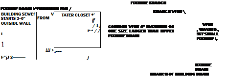
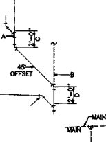
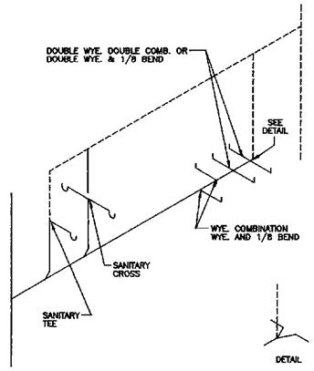
Riser drawings are used when figuring out drainage systems, just as they are used with vent systems. I want to give you some sample riser diagrams to look over. The drawings will show you what your drawings might look like. Drains are drawn with solid lines, while vents are indicated by broken lines.
|
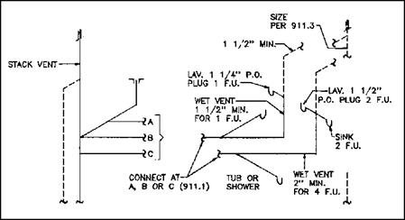
FIGURE 4.26 ■ Wet venting top floor single bath group. (Courtesy of Standard Plumbing Code) |
|
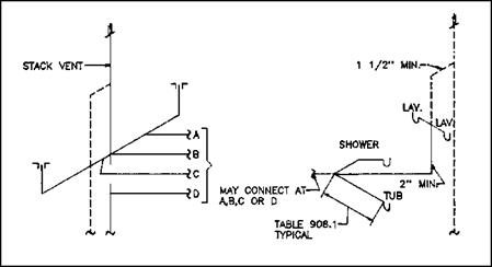
FIGURE 4.27 ■ Wet venting top floor double bath back to back. (Courtesy of Standard Plumbing Code) |
|
|
||
|
|||
 |
|||
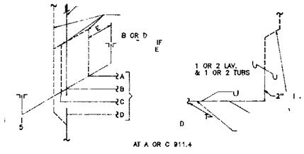

FIGURE 4.28 ■ Wet venting lower floors on multistory buildings. (Courtesy of Standard Plumbing Code)
 |
|
|
|
|
|
|
|
 |
|
 |
|
|
|

![]()

|
|
|
|
|
|
|
|
|
|
|
|
|
|
|
|
|
|
|
|
|
|
 |
|
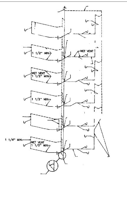

FIGURE 4.30 ■ Multistory wet venting. (Courtesy of Standard Plumbing Code)
|
|
|
|
|||
|
|
||
|
|||
|
|||
|
|||
|
|||
|
|||
|
|||
 |
|||
|
|||
|
|||
|


![]()

|
|
|
|
|
|
|
|
|
|
|
|
|
|
|
|
|
|
|
|
|
|
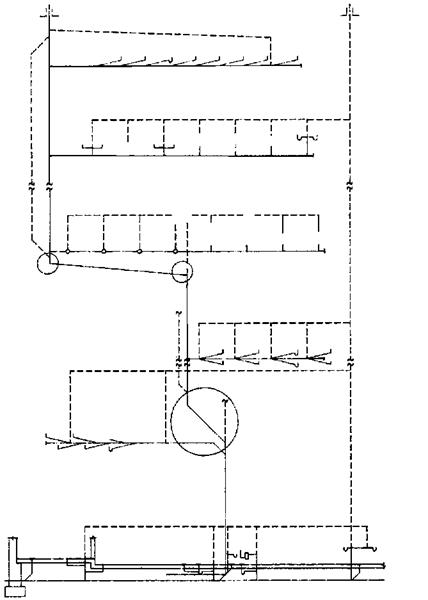

FIGURE 4.33 ■ Drainage waste and vent reference diagram. (Courtesy of Standard Plumbing Code)
|
|
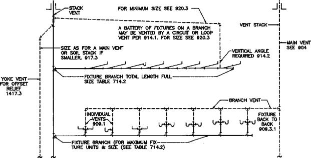
FIGURE 4.34 ■ Fixtures back-to-back in battery. (Courtesy of Standard Plumbing Code)


Leave a reply