|
A 3.4 Determine the developed length ot pipe from the water (street) main to the highest fixture. If close estimates are desired, compute with the aid of Table A-З the equivalent length of pipe for all fittings in the line from the water (street) main to the highest fixture and add the sum to the developed length. The pressure available for friction loss in pounds per square inch (kPa), divided by the developed lengths of pipe from the water (street) main to the highest fixture, times one hundred (100), will be the average permissible friction loss per one hundred (100) foot (30.4m) length of pipe.
A 4 Size of Building Supply
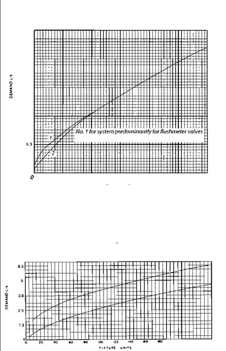
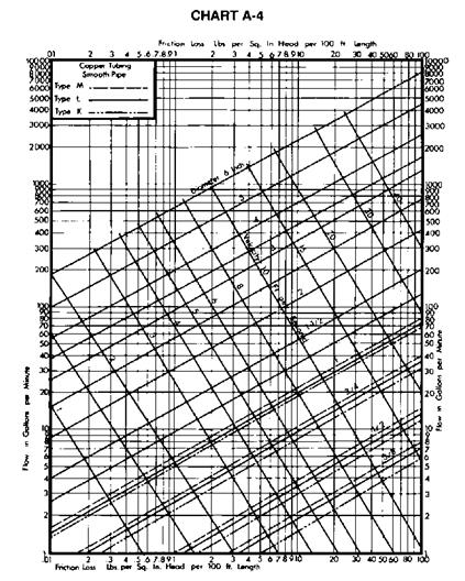
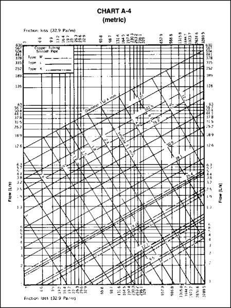
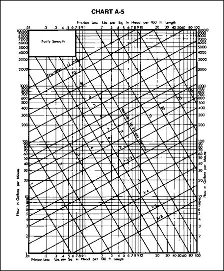
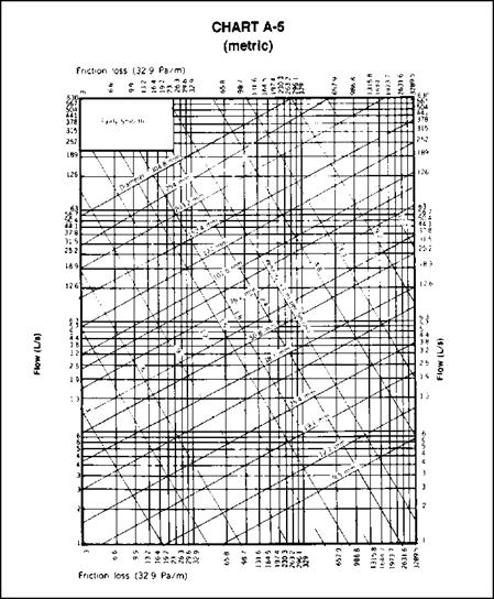
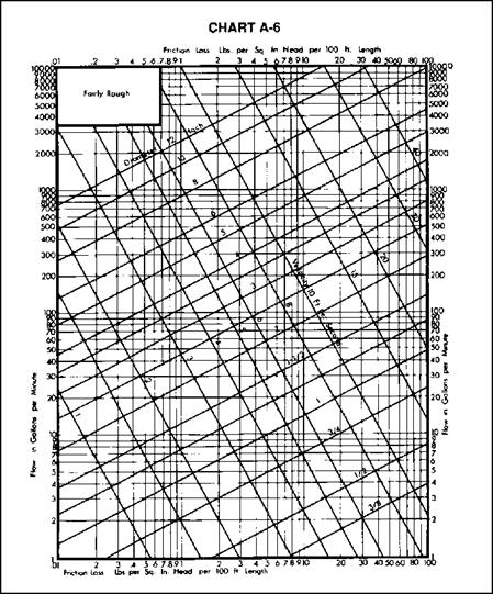
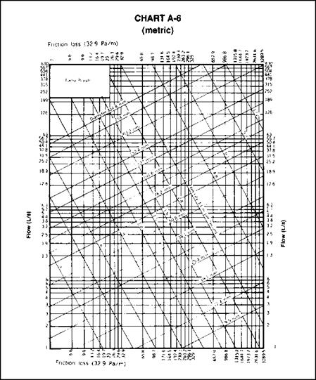
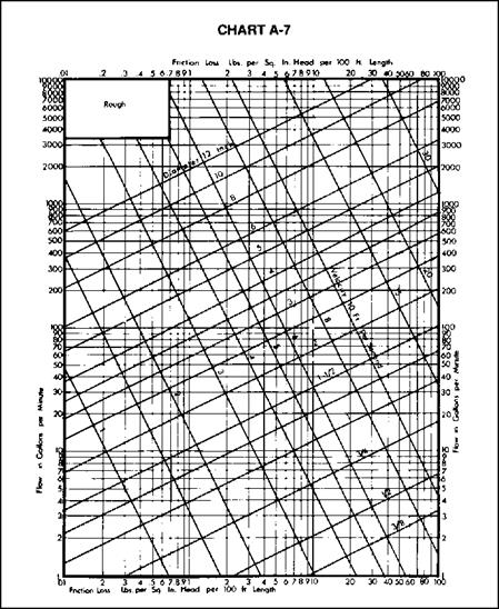
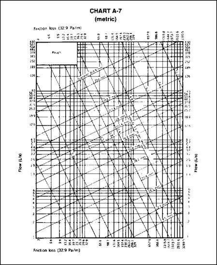
A 4.1 Knowing the permissible friction loss per one hundred (100 feet (30.4 m) of pipe and the total demand, the diameter of the building supply pipe may be obtained from Charts A-4, A-5, A-6, or A-7, whichever is applicable. The diameter of pipe on or next above the coordinate point corresponding to the estimated total demand and the permissible friction loss will be the size needed up to the first branch from the building supply pipe.
A 4.2 If copper tubing or brass pipe is to be used for the supply piping, and if the character of the water is such that only slight changes in the hydraulic characteristics may be expected, Chart A-4 may be used.
A 4.3 Chart A-5 should be used for ferrous pipe with only the most favorable water supply as regards corrosion and caking. If the water is hard or corrosive, Charts A-6 or A-7 will be applicable. For extremely hard water, it will be advisable to make additional allowances for the reduction of capacity of hot water lines in service.
A 5 Size of Principal Branches and Risers
A 5.1 The required size of branches and risers may be obtained in the same manner as the building supply by obtaining the demand load on each branch or riser and using the permissible friction loss computed in Section A 3.
A 5.2 Fixture branches to the building supply, if they are sized for the same permissible friction loss per one hundred (100) feet (30.4 m) of pipe as the branches and risers to the highest level in the building, may lead to inadequate water supply to the upper floor of a building. This may be controlled by: (1) selecting the sizes of pipe for the different branches so that the total friction loss in each lower branch is approximately equal to the total loss in the riser, including both friction loss and loss in static pressure; (2) throttling each such branch by means of a valve until the preceding balance is obtained; (3) increasing the size of the building supply and risers above the minimum required to meet the maximum permissible friction loss.
A 5.3 The size of branches and mains serving flushometer tanks shall be consistent with sizing procedures for flush tank water closets.
|





Leave a reply