Blog Archives

U. S. METHOD

This method emerged in 1990 after a tour of Europe when some U. S. engineers learned of the benefits of SMA. A series of research efforts started soon after to develop a method of designing SMA. This resulted, among other things, in publica­tions (Brown and Haddock, 1997; Brown and Mallick, 1994) that tried to reach to the heart of the matter of SMA mixtures and suitable methods of designing and testing them.

The essential aspect of designing an SMA aggregate mix using the U. S. method is the introduction of the idea of stone-to-stone contact, or a direct contact among coarse particles. Those grains, called active grains, make a strong mineral matrix and give the SMA its deformation resistance. The method of testing the stone-to-stone contact has also been defined...

read more

Safety on the Job MAKING A LAYOUT STICK

Подпись: ISafety on the Job MAKING A LAYOUT STICK

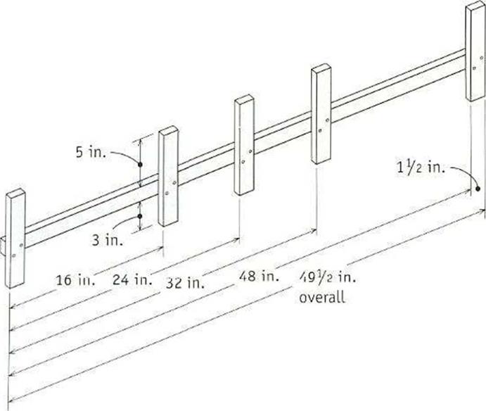
WHETHER YOU USE a store-bought layout stick or make your own, this tool will save you a lot of time when marking plates in preparation for wall con­struction. A stick like the one shown here can be used to lay out studs on 16-in. and 24-in. centers.

To make your own layout stick, cut a series of ІУг-in.-wide strips from a panel of 34-in.-thick ply­wood. Cut one strip 497? in. long and five strips 97? in. long. Glue and nail the short pieces to the long piece at right angles and at the spacing shown in the illustration. The З-in. legs allow you 😮 mark top and bottom plates at the same time. The 5-in. legs make it easy to mark two plates side by side and to mark headers and rough sills along with the plates.

indicate the studs’ locations. This will give vou a 14k:-in...

read more

Services Too Dispersed

Zoning as we know it basically began in nineteenth-century Europe. Indus­trialized cities were shrouded in coal smoke, so urban planners rightly sug­gested that factories be separated from residential areas. Life expectancies soared, the planners gloated, and segregation quickly became the new solu­tion to every problem. So, while in the beginning only the incompatible func­tions of a town were kept apart, now everything is. Housing is separated from industry, low-density housing is kept separate from existing, higher-density housing, and all of this is kept far from restaurants, office buildings and shop­ping centers, which are all kept separate from each other.

With the dispersal have come mandatory car ownership and the end of pe­destrian life as we once knew it...

read more

Volumetric Parameters

The volumetric relationship in an asphalt mixture is shown schematically in Figure 7.1 in German terms. Equations are based on TP A-08 2007 and Hutschenreuther and Woerner (2000).

Symbols in Figure 7.1 include the following:

Hbit = Volume of voids in compacted asphalt samples, % (v/v)

Bv = Binder volume, % (v/v)

Mv = Mineral aggregate volume, % (v/v)

HMbit = Voids in mineral aggregate (VMA), % (v/v)

Obviously, the sum of all the parts should equal 100%.

MV + BV + Hbit = 100%

The way of calculating volume parameters and defining them is outlined here.

Подпись: Hhit

Volumetric Parameters Подпись: Binder volume

Air voids

Aggregate volume

Mv

FIGURE 7.1 Volume relationship in an asphalt mixture according to terminology adopted in Germany. (From Graf, K., Splittmastixasphalt—Anwendung und Bewahrung. Rettenmaier Seminar eSeMA’06...

read more

Coupled Physical-Mechanical Water-Induced Damage

One of the important realizations is that the problem cannot be solved by mechanical considerations alone. Clearly, water has an effect on the material characteristics of the asphaltic components and their bond, even without mechanical loading. There­fore, both physical and mechanical water damage-inducing processes are included in the model. Another realization is that, in order to acquire a fundamental insight into the processes which cause water damage, the asphaltic mixture needs to be considered at a micro-scale. This implies that the experimental characterization and the computational simulations of the water damage-inducing processes must be dealt with at mixture component level; i. e...

read more

Rehabilitation of Flexible Pavement

Asphalt Overlay. Without question the most common method of rehabilitation for flexible pavement is an asphalt overlay. There are many variations of this technique ranging from pavement planing and a thick asphalt overlay to a thin skin patch placed infrequently along a pavement. The existing condition of the asphalt pavement and the results of nondestructive testing dictate the most economical strategy. The pavement can be designed as a layered system.

Whitetopping. The construction of a concrete pavement on an existing asphalt pave­ment is termed whitetopping. An asphalt pavement provides an excellent base for a rigid pavement. The concrete pavement is designed as if it were a new pavement con­structed on an asphalt base...

read more

METHODS OF PAVEMENT REHABILITATION

Once a pavement is determined to have unacceptable smoothness or has lost its ability to properly transport goods, it is reasonable to determine the best strategy to return the pavement to its original intended function. Many of the decisions that define the point where corrective action should be taken are management decisions and can be addressed properly only in a comprehensive study of pavement management data. Many considerations must be addressed before determining a list of good rehabilitation options. Leading rehabilitation techniques are reviewed in the following articles.

3.9.1 Rehabilitation of Rigid Pavement

CPR. The most common method of restoration for jointed pavement, both reinforced and nonreinforced, is termed concrete pavement restoration (CPR)...

read more

Overview of SMA Design Methods

The basic and universal rules of stone matrix asphalt (SMA) design were described in the previous chapter. Chapter 7 provides an overview of SMA design methods devel­oped in various countries. Undoubtedly, there are many of them, so their description could be the subject of a separate book. We will focus here on the most distinctive or the most interesting ones available in the technical literature.

The literature about SMA design methods can be both instructive and creative. You may judge for yourself which method most closely fits your needs or seems to have the most merit.

7.1 GERMAN METHOD

7.1.1 Description of the Method

The German method is based on long-standing experience in the application of repeatable materials and mixes...

read more

SIZING TABLES

Sizing tables are often used when sizing vent pipes (Fig. 5.21). There can be many different types of tables to use during a sizing procedure. For example,

lVa

’Л

lVi

Unlimited

lVi

V4

1V2

Unlimited

2

Vi

1 Vi

290

2

Vi

lVi

Unlimited

3

Vi

1V2

97

3

Vi

2

420

3

Vi

3

Unlimited

4

Vi

2

98

4

Vi

3

Unlimited

4

Vi

4

Unlimited

Drain pipe size (in)

Drain pipe size

(in/ft)

Vent pipe size (in)

Maximum developed length of vent pipe (ft)

FIGURE 5.21 ■ Vent sizing table for Zone Three (for use with individual, branch, and circuit vents for horizontal drain pipes). (Courtesy of McGraw-Hill)

Подпись: Wet-vented fixtures 1 to 2 Bathtubs or showers 3 to 5 Bathtubs or showers 6 to 9 Bathtubs or showers 10 to 16 Bathtubs or showers Подпись: Stack size required (inches) 2 2 Vi 3 4

you might use one table to size a vent stack (Fig. 5...

read more

WALL FRAMING ANATOMY

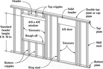
WALL FRAMING ANATOMYSTUDS are spaced on 16-in. or 24-in. centers. The length of the stud determines the overall height of the wall. Stan­dard stud length is 92% in.

KING STUDS are full-length studs used on either side of a door or window opening. They back up trimmer studs and are nailed against the ends of the header and (for window openings) to rough sill.

TRIMMERS (also called trimmer studs) frame the sides of rough openings. They extend along king studs to support ends of headers.

CRIPPLES, often called jack studs, span the distance be­tween top plates and headers and between bottom plates and rough sills.

The BOTTOM PLATE is fastened to the floor deck or to a concrete slab floor.

The TOP PLATE is nailed to studs and cripples.

The DOUBLE TOP PLATE adds rigidity to the top of the wall and overlaps the to...

read more