Blog Archives

Engineered Lumber Products

I-Joists

I-joists were introduced in 1968 by the Trus Joist Corporation. Although use of this product has grown rapidly over the years, there is still no industry standard for its manufacture and installation. And while the Engineered Wood Association (APA) has established a standard for its members, not all manufacturers are members of APA. Because there is no universal standard, it’s important to use the installation instructions that come in the I-joist package. The package is generally prepared by a manufacturer’s representative working with the architect or designer.

The I-joist package should include installation plans for the building. These plans will be specific to the
building you are working on, and will include a material list and accessories...

read more

Rigid Systems

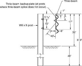
The concrete safety shape system (Fig. 6.21), which has a sloping front face, is similar to the concrete median barrier (Art. 6.9.1) but usually has a vertical back face. The reduced cross-section of the roadside barrier version makes it more vulnerable to over­turning, thus requiring more reinforcing steel and/or a more elaborate footing design. The New Jersey shape at a height of 32 in (810 mm) meets TL-4 and at a height of 42 in (1070 mm) meets TL-5. Both the New Jersey profile and the F-shape profile shown in Fig. 6.21 are acceptable. The F-shape reportedly showed better performance in crash tests with 1800-lb (820-kg) cars and 18,000-lb (8000-kg) single-unit trucks. Higher designs have been tested and constructed to redirect heavy vehicles. For example, the

Подпись: AASHTO Designation: Post Type: Offset Block: Post Spacing: Beam Type: Nominal Barrier Height: Maximum Dynamic Deflection:

Rigid Systems

None

W6 x 9 steel...

read more

Water lifts, paddlewheels, and water mills in the world of Vitruvius

Vitruvius provides the oldest known description of a water lift powered by hydraulic force, or noria, and of a water mill. This description comes immediately after that of manual water lifts (drum wheel, bucket wheel: see Figure 6.20):

“Wheels on rivers are constructed upon the same principles as those just described (manual lift wheels). Round their circumference are fixed paddles (pinnae), which, when acted upon by the force of the current, drive the wheel round, receive the water in the buckets, and carry it to the top with the aid of treading; thus by the mere impulse of the stream supplying what is required.

“Water mills (hydraletae) are turned on the same principle, and are in all respects similar, except that at one end of the axis they are provided with a drum-wheel, toothed and ...

read more

Semirigid Systems

The box-beam (weak-post) system (Fig. 6.16) achieves its resistance through the com­bined flexural and tensile resistance of the box beam. Posts near the impact point are designed to break or tear away and distribute the impact force to adjacent posts. This system meets TL-3. The system is sensitive to mounting height and irregularities in terrain.

The blocked-out W-beam (strong-post) system (Fig. 6.17) is the most common barrier. The blockout or offset of the rail from the post minimizes vehicle snagging and reduces likelihood that a vehicle would vault over the barrier. The system is classified as TL-2 or TL-3, depending upon the type of blocks...

read more

Compaction Factor

Almost all documents on SMA reviewed for the purposes of this book contain the compaction factor as a specified requirement. As in many other cases, the differ­ences between European and U. S. specifications are clear.

That factor has been defined differently in different countries. The differences are grounded in the different reference density used related to the bulk density of the layer achieved on the construction site. That is the source of the sharp differences in numerical values: from 94% (the United States.) to 98% (Norway). The description of two basic definitions of the compaction factor follows later on.

Mix design After construction End of service life

FIGURE 10.13 Change in the content of air voids in an SMA layer. (From Voskuilen, J. L.M...

read more

Monte Carlo Simulation

6.1 Introduction

As uncertainty and reliability related issues are becoming more critical in en­gineering design and analysis, proper assessment of the probabilistic behavior of an engineering system is essential. The true distribution for the system response subject to parameter uncertainty should be derived, if possible. How­ever, owing to the complexity of physical systems and mathematical functions, derivation of the exact solution for the probabilistic characteristics of the system response is difficult, if not impossible. In such cases, Monte Carlo simulation is a viable tool to provide numerical estimations of the stochastic features of the system response.

Simulation is a process of replicating the real world based on a set of assump­tions and conceived models of reality (Ang and...

read more

The three-cable system (Fig. 6.13) has been successfully tested to TL-3. It is made up of three steel cables mounted on weak posts. The cable barrier redirects impacting vehicles after the cable deflects and develops tension, with the posts offering little direct resistance. Several states allow a backslope as steep as 1:2 behind the rail. If the barrier is placed on the inside of a curve, additional deflection will occur before tension develops in the cable, and thus it may be desirable to limit the radius. New York installs the barrier having S3 X 5.7 (S75 X 8.5) steel posts for radii of 721.5 ft (220 m) or more with the standard 16-ft (4.9-m) post spacing, and for radii of 442.5 ft (135 m)

TABLE 6.2 Classification of Roadside Barriers and Approved Test Levels

Barrier system Test level

Flexible systems

Three-strand cable (weak-post) TL-3

W-beam (weak-post) TL-2

Modified W-beam (weak-post) TL-3

Ironwood aesthetic barrier TL-3

Semirigid systems

Box-beam (weak-post) TL-3

Blocked-out W-beam (strong-post)

Steel or wood post with wood TL-3

or plastic block

Steel post with steel block TL-2

Blocked-out thrie-beam (strong-post)

Wood or steel post with wood TL-3

or plastic block

Modified thrie-beam (strong-post) TL-4

Merritt Parkway aesthetic guardrail TL-3

Steel-backed timber guardrail TL-3

Rigid systems (concrete and masonry)

New Jersey concrete safety-shape

32 in (810 mm) tall TL-4

42 in (1070 mm) tall TL-5

F-shape barrier

32 in (810 mm) TL-4

42 in (1070 mm) TL-5

Vertical concrete b...

read more

Grout Sealers

Sealing grouts will make grout joints easier to clean and more resistant to water penetration and staining. When water penetrates grout joints, it makes them susceptible to mold and bacterial growth. Even grouts containing mil – dewcides can eventually become moldy. Be­sides sealing grouts in wet areas, the key to mold-free grout is maintenance. Bathrooms should be kept dry by using exhaust fans, and grout joints should be cleaned regularly We do not recommend the commercially avail­able grouts enhanced with additives. We have found the following sealing methods to be generally well-tolerated by chemically sensi­tive individuals:

• AFM Safecoat Grout Sealer: A clear, moisture-resistant sealer for porous tile grout to help prevent staining

• AFM Safecoat Safe Seal: An odorless, zero-VO...

read more

MORE SIDING OPTIONS

Подпись: The exterior of the house can be closed in rapidly with sheets of textured plywood or OSB. [Photo by Don Charles Blom] Подпись:MORE SIDING OPTIONS

In addition to vinyl siding, there are three more exterior finishes to consider if you’re interested in affordability, low maintenance, and attractive appearance:

COMPOSITE WOOD. These planks are made the same way as OSB sheathing panels, but they look like solid – wood clapboards or horizontal lap siding when installed. This siding comes with a factory-applied primer coat, and it needs to be painted after installation. Composite-wood planks don’t split, crack, or warp like solid-wood siding does, but they may not be a wise choice in extremely wet climates. These clapboards nail on walls much like cement fiber boards.

STUCCO. Two types of stucco finishes can be applied to house exteriors...

read more

Paddle wheels and water mills in the Roman world, the beginnings of industrial use of water

In the provincial countryside some ten kilometers from Arles in the direction of Saint-Remy-de-Provence, a hiker can come upon the remains of Roman aqueducts on arches. These remains are even indicated by a sign. Looking at the remains closely, the tourist can easily see that there are in fact two parallel aqueducts, side by side. If the hiker follows the path alongside these aqueducts, he or she comes upon a deep notch cut in a rocky outcrop. The canal of the left aqueduct passes through this notch (Figure 6.19).

After passing through this notch, our hiker then comes out at the top of an escarp­ment, 20 meters high along a length of 60 meters, beyond and below which is a broad plain with no visible trace of the aqueduct...

read more