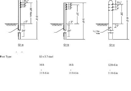
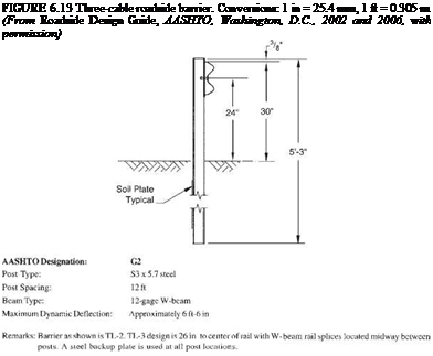
The three-cable system (Fig. 6.13) has been successfully tested to TL-3. It is made up of three steel cables mounted on weak posts. The cable barrier redirects impacting vehicles after the cable deflects and develops tension, with the posts offering little direct resistance. Several states allow a backslope as steep as 1:2 behind the rail. If the barrier is placed on the inside of a curve, additional deflection will occur before tension develops in the cable, and thus it may be desirable to limit the radius. New York installs the barrier having S3 X 5.7 (S75 X 8.5) steel posts for radii of 721.5 ft (220 m) or more with the standard 16-ft (4.9-m) post spacing, and for radii of 442.5 ft (135 m)
TABLE 6.2 Classification of Roadside Barriers and Approved Test Levels
Barrier system Test level
Flexible systems
Three-strand cable (weak-post) TL-3
W-beam (weak-post) TL-2
Modified W-beam (weak-post) TL-3
Ironwood aesthetic barrier TL-3
Semirigid systems
Box-beam (weak-post) TL-3
Blocked-out W-beam (strong-post)
Steel or wood post with wood TL-3
or plastic block
Steel post with steel block TL-2
Blocked-out thrie-beam (strong-post)
Wood or steel post with wood TL-3
or plastic block
Modified thrie-beam (strong-post) TL-4
Merritt Parkway aesthetic guardrail TL-3
Steel-backed timber guardrail TL-3
Rigid systems (concrete and masonry)
New Jersey concrete safety-shape
32 in (810 mm) tall TL-4
42 in (1070 mm) tall TL-5
F-shape barrier
32 in (810 mm) TL-4
42 in (1070 mm) TL-5
Vertical concrete barrier
32 in (810 mm) TL-4
42 in (1070 mm) TL-5
Single-slope barrier
32 in (810 mm) TL-4
42 in (1070 mm) TL-5
Ontario tall-wall median barrier TL-5
Stone masonry wall/precast TL-3
masonry wall
Source: From Roadside Design Guide, AASHTO,
Washington, D. C., 2002 and 2006, with permission.
or more with a 12-ft (3.7-m) post spacing. Advantages of the three-cable barrier include low initial cost, effective vehicle containment and redirection over a wide range of vehicle sizes and installation conditions, low deceleration forces, and functionality in snow or sand areas because the open design prevents drifting. Disadvantages include the long lengths that are nonfunctional and must be repaired after an impact, the clear area behind the barrier needed to accommodate the design deflection distance, reduced effectiveness on the inside of curves, and sensitivity to correct height installation and maintenance.
The W-beam (weak-post) system (Fig. 6.14) behaves much like a cable system, but the deflection is much less. Thus, the required clear area behind the barrier is less. The

|
|
||
|
|||
|
|||

Post Spacing:

![]() Beam Type:
Beam Type:
Maximum Dynamic Deflection:

Remarks: For shallow angle impacts, barrier damage is usually limited to several posts, which must be replaced. Cable damage is rare except in severe crashes. A crashworthy end terminal is critical in each of the cable systems, both to provide adequate anchorage to develop full tensile strength in the cable and to minimize vehicle decelerations for impacts on either end of an installation.
 system meets Tl-2 or TL-3, depending upon details. The system is sensitive to mounting height and irregularities in terrain.
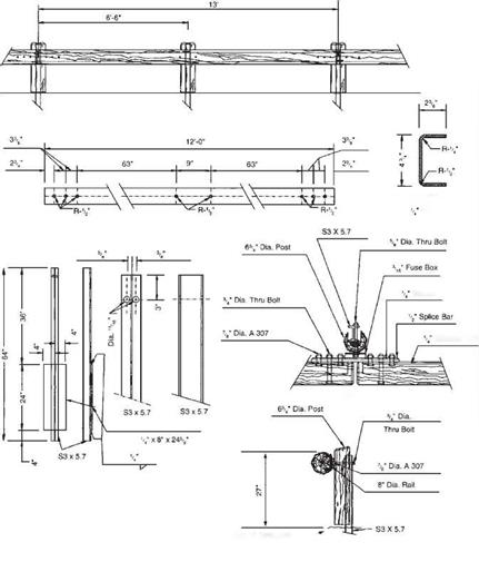
The Ironwood barrier shown in Fig. 6.15 is a proprietary weak-post system that meets TL-3. It has a composite rail that consists of round-wood sections with steel channels embedded on the backside. The steel support posts are faced with timber posts above the ground line. Thus, the system presents an all-timber appearance. Crashworthy terminal designs have not been developed but the ends may be anchored in a backslope or flared to the edge of the clear zone.
ELEVATION
CHANNEL RAIL
PLATE
CHANNEL RAIL ELEVATION
Washer
Channel Rail
PLAN
STEEL POST
Edge of Pavement or^"’ Groundline at Face of Rail
SIDE


Leave a reply