Blog Archives

Fin Drains

Fin drains or drainage screens are also longitudinal drains, manufactured from com­posite materials. Their essential make-up is of two geotextile faces that provide a filter function between the surrounding ground and a rigid plastic core that is sandwiched between the geotextile faces – see Fig. 13.16c. The so-called “drainage core” is, typically, formed of a high-density polyethylene, HDPE, structure. Often this feeds into an integral collector at the bottom. The core permits the water to flow in the plane of the geocomposite (compared with most simple geosynthetics

in which only cross-flow can readily take place). These drains are usually placed at the pavement’s edge, allowing the collector of percolating water (Fig. 13.16a & b)...

read more

Trench Drains (“French” drains)

A trench drain consists of drain wrapped in geotextile, see Figs. 13.13-13.15. The drain is made of a mineral material such as a rounded or crushed aggregate. Origi­nally either no carrier pipes orun-jointed pottery pipes were employed at the bottom of such drains. Nowadays, several materials are used for this type of pipe, from perforated or porous concrete, to PVC and fibreglass, the last ones with grooves or perforations. The pores, joints, perforations or grooves are designed to allow water collection. Typical diameters vary from 150 to 200 mm, with a longitudinal gradient that satisfies the self-cleaning condition (> 0.25%). Whenever these drains reach

Fig. 13.13 Conventional trench drain

their maximum capacity, a lateral pipe with the adequate discharge capability should be pl...

read more

Flooring

Подпись:

In the old days,

building material to be installed and the first to show its age, as it was crushed by footsteps, swollen by moisture, and abraded by dirt. Foot traffic is as heavy and gritty as ever, but today’s crop of engineered flooring and floor finishes is far more durable—and varied.

However, flooring is only the top layer of a sys­tem that usually includes underlayment and sub­flooring, as well as structural members such as joists and girders. If finish floors are to be solid and long lasting, all parts of the flooring system must be sized and spaced correctly for the loads they will carry. Also, although some flooring mate­rials can withstand moisture better than others, all will degrade in time if installed in chronically
damp locations...

read more

TYPES OF NOISE BARRIERS

Except for berms and brick or masonry construction, most noise barriers are of post-and – panel construction, that is, vertical posts spaced a distance apart with horizontal or verti­cal panels running in between. Rails or girts may also run between the posts to support the panels. Posts are embedded in the foundation soil to design depth, which depends on wind loading, soil properties, and frost depth. Brick and masonry walls generally require spread footings, underlain with uniform layers of soil.

According to a 2006 FHWA survey, the main materials that have been used for noise wall construction, in order of usage, are the following:

• Concrete

• Block and brick

• Wood

• Metal

• Earth berms

Other materials sometimes used include plastic, glass, composites, and gabions (rock- f...

read more

PAPERING AROUND ELECTRICAL OUTLETS AND FIXTURES

О Turn off electricity to the affected outlets and fixtures, and confirm that it’s off by using a voltage tester, as shown on p. 235. Remove the cover plates and other hardware from the outlets so the hardware protrudes as little as possible.

For an outlet relatively flush with the surface, simply position the strip over it. Then, over the center of the outlet, cut a small Xin the strip. Gradually extend the legs of the X until the strip lies flat. Even though the outlet’s cover plate will cover small imperfections in cutting, cut as close as you can to the edges of protruding hardware or the electrical box. Smooth the strip with a smoothing brush, and trim any excess paper. If the edges of the cutout aren’t adhering well, roll them with a seam roller.

It’s preferable to remove fixtures s...

read more

Risk-based design without flood damage information

Conventional risk-based design and analysis ofhydrosystems requires informa­tion with regard to various flood-related damages. Such information requires an extensive survey of the type and value of various properties, economic and
social activities, and other demographic-related information in the regions that are affected by floods. For areas where flood-related damage data are unavail­able, conventional risk-based analysis cannot be implemented, realizing that in any design or analysis of a hydrosystem one normally has to conduct hy­draulic simulation to delineate the flood-affected zone and other related flow characteristics, such as water depth and flow velocity...

read more

REQUIREMENTS FOR AN SMA MIX

An SMA formula has to be documented and demonstrated (declared). Any SMA mixture made according to the recipe has to meet the standard requirements deter­mined by a given country.

14.5.1 Gradation

The fundamental rules regarding the mix design include the following:

• The gradation should be expressed in mass percentages of the total aggre­gate mix; the accuracy of percentages passing

• all sieves (with the exception of the 0.063 mm sieve) should be expressed to 1%.

• the 0.063 mm sieve should be expressed to 0.1%.

• The content of binder and additives should be expressed in mass percent­ages of the asphalt mixture, with an accuracy of 0.1%.

• The type of fine aggregate used and the adopted ratios in the case of a mix may be given in a recipe or specification.

• The gradation ...

read more

Techniaues CUTTING A COPED JOINT

IF YOU’RE INSTALLING BASEBOARD TRIM that

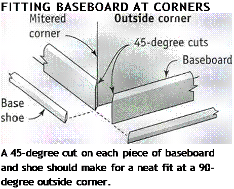
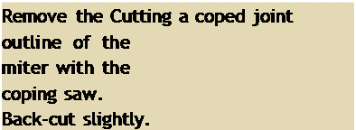
Подпись: FITTING BASEBOARD AT CORNERS A 45-degree cut on each piece of baseboard and shoe should make for a neat fit at a 90-degree outside corner. Подпись: Remove the Cutting a coped joint outline of the miter with the coping saw. Back-cut slightly. Подпись: 45-degreeПодпись: angle Miter /Techniaues CUTTING A COPED JOINTПодпись:Подпись: sawПодпись: Inside cornerПодпись: A coped joint makes a trim fit on an inside corner.Techniaues CUTTING A COPED JOINT

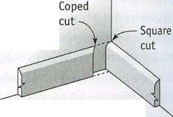
has a rectangular profile, butt one board into another at an inside corner. For baseboard trim that has a shaped profile, it’s customary to make inside corners using coped joints. Coped joints can also be used on inside corners when installing chair rail, base shoe trim, and crown molding.

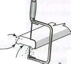
Start by setting a piece of trim upright in the chopsaw and make a 45-degree cut so you can see the face grain of the wood. The long point of the miter cut is toward the back of the material. Then, using a coping saw (or a small jigsaw) fitted with a fine-tooth blade, carefully cut along the outline of the exposed end grain. Tip the saw back a few degrees to give the wood a slight back-cut...

read more

The golden age of the Chinese navy, 9th to the 15th century On the rivers, boats powered by paddle wheels

From the time of the first emperor there was a need for warships in support of military campaigns in the basins of the Yangtze and the Xi (near Canton). These fortified, and sometimes armored, ships were initially powered through oars manned by soldiers. But the specific needs of riverborne military operations led to a very curious invention. It was in 784, under the Tang, that a prince named Li Gao developed warships powered by paddlewheels.[456] This invention may well have come from the 5th century.

This type of boat sees major development on the Yangtze, pushed by a great naval architect named Gao Xuan, at the beginning of the 12th century when the Song retreat into south China...

read more

Magnetic Fields from Three – and Four-Way Switches

Lights switched from two different locations are called three-way switches. When lights are switched from three or more locations, they

Magnetic Fields from Three - and Four-Way Switches

ground

ndr $ho/Ui


adwg^d (joined^) from Separate ‘circuit


в


deafer

A


^eker c||


trow б^рйгаге cirom’te Kepir е>е£йг<а(ге


nfr


10 ,

greater

0


Magnetic Fields from Three - and Four-Way SwitchesMagnetic Fields from Three - and Four-Way Switches

Magnetic Fields from Three - and Four-Way Switches

A: 1/2 switched outlet. Both hot and neutral pre-scored conduction tabs must be snapped off when the upper and lower outlets are supplied by separate breakers.

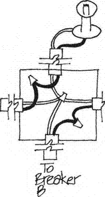
B: Ganging Neutrals. This wiring configuration is wrong and will create net current and magnetic fields.

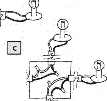
C:This diagram shows the correct configuration, which will not generate magnetic fields.

Подпись:Подпись: 2 wire RomexMagnetic Fields from Three - and Four-Way Switches2 fomex

1 hot"

I neutral J ground

Properly w...

read more