The water delivery system of Pergamon: the first large forced main
Lysimachus, who had received Thrace in the partition of Alexander the Great’s empire, imprudently left part of his war spoils in the custody of Philetairos, in the Asia Minor citadel of Pergamon. This citadel occupied a rocky spire that overlooked the plain from 300 m above it, and about 30 km from the sea. After the secession of Philetairos, in 282 BC, Pergamon rapidly became the capital of a kingdom, then an intellectual center that sought to rival Alexandria with a great Library (some 200,000 rolls of papyrus) and a School of original thought.
The provision of a supply of water to these citadels perched on hills always posed a problem in Antiquity. Initially, cisterns were built to store rainwater. Later, tunnels (or sinnors) were often dug to ensure access, especially during sieges, to underground cisterns fed by springs located on the flanks of the hills; this was the solution adopted at Mycenae, and at Jersusalem.
|
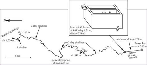
Figure 5.8 The Hellenistic aqueduct of Mandradag for water delivery to Pergamon (after Garbrecht, 1983) |
Having become a powerful city, Pergamon needed water, and this need was met with an unprecedented hydraulic installation. The project was founded on the understanding of the hydraulic concept of a siphon and the experience of the first Hellenistic applications, as well as on the mastery of the metallurgy of lead. This project is known to us through site studies carried out by a German team between 1968 and 1972.[178] Its construction was probably carried out during the reign of King Eumene II (197 – 159 BC). This water delivery system comprises two parts (Figure 5.8). The upstream portion brings water from the Mandradag spring (captured at an altitude of 1,230 m) as well as from other springs, some as far away as 25 km as the crow flies, to a reservoir located 3 km from the city across from the citadel, at an altitude of 376 m (i. e. about 26 m higher
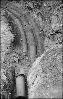
than the citadel). This original project includes parallel buried pipelines (three of them downstream of the Kemerdere spring) assembled from about 200,000 connected clay sections (Figure 5.9). These sections are from 50 to 70 cm long, with interior diameters from 16 to 19 cm, and wall thicknesses of about 4 cm. The watertight joints between the sections are built up from a mixture of sand, mud, and clay, including certain organic matter such as petroleum or greases.[179] The parallel pipelines follow the slope of the land along a total length of more than 40 km. They do not flow under pressure, and thus in principle belong to the family of water delivery systems developed earlier in Greece (see the end of Chapter 4) – but on a larger scale.
 Figure 5.9 The three clay pipelines of the Mandradag aqueduct (photo of G. Garbrecht).
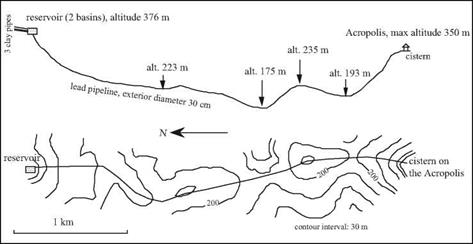
It is the second section of the pipeline that, although much shorter, is of revolutionary conception (Figure 5.10). It conveys water from the reservoir that we just described, at an altitude of 376 m, down to the citadel at 350 m, in a straight-line distance of only 3 km. But this section crosses a valley whose lowest elevation is only 175 m, i. e. nearly 200 m below the reservoir. The inverse siphon comprises a pressure conduit made of lead, with an outside diameter that appears to have been 30 cm, the inside diameter
appearing to be the order of 20 cm.[180] The conduit is not buried, but rests on aboveground stone supports. No visible traces remain of the forced main itself (the metal, having considerable value, was ultimately recovered for other uses). But the conduit’s support blocks, with their 30-cm holes, have been recovered, along with massive anchor blocks on the two high points of the profile, to withstand static and hydrodynamic forces. Traces of lead have been found on the ground along the course of the conduit. The longitudinal profile of the pipeline (Figure 5.10) is in the form of a W, unlike the earlier U- shaped Hellenistic siphons. It seems that the designers of the facility, concerned with the effects of hydrostatic pressure corresponding to 200 m of elevation difference, sought to limit the length of pipe sections subject to the greatest pressure. They appeared to have done so by intentionally routing the conduit over intermediate high points within the depression. At these intermediate high points, there is a risk of the formation of air pockets that can endanger a pipe system in several respects. Air release vents were very likely installed at these locations.
|
Figure 5.10. Longitudinal profile and routing of the inverted siphon of Pergamon: the first large forced main (Hodge, 1995). |
The discharge in this system has been estimated to be 45 l/s (i. e. nearly 3,900 m3 per day). Later, urbanization spreads to the low areas situated at the foot of the hill. New aqueducts will be built, in particular during the period of Roman domination, to supply these low areas. But none of these aqueducts can rival the audacity of the Mandradag pipeline, the only one to provide water to the summit of the Acropolis. No subsequent Roman aqueduct will ever approach the bold technical audacity of this forced main.


Leave a reply