MAPPING STRUCTURE AND UTILITIES
Renovations beyond cosmetic changes will probably require some alteration of the structure as well as of plumbing, electrical, and heating/ cooling systems. As with many other aspects of renovation, it’s usually best to disturb as little as possible. Until you demolish walls you won’t know the exact location of every last pipe and wire, but by mapping what you can see, you’ll get a sense of where larger, more problematic ducts and pipes are, and thus save time and money by not proceeding with an obviously impractical design.
Now, using the floor plans you drew earlier as templates, create a map for each house system. For each system, use a tracing-paper overlay or mark up a photocopy of the basic floor plan, whichever is more convenient. While you’re examining each room, it’s also smart to note water stains, tired windows, outdated fixtures, ungrounded outlets, sagging floors, and so on. Use the various house assessment lists in Chapter 1 to guide you.
Structural elements should be assessed by a licensed structural engineer, who should also review any design plans that require altering or removing structure. Usually, the big question is whether the walls to be removed are load bearing, and that answer is not always obvious. In addition, in high-wind or earthquake regions, walls may be shear walls, which help a building resist lateral (sideways) forces. Don’t cut or drill into, run pipes through, or remove shear walls until a structural engineer has okayed it.
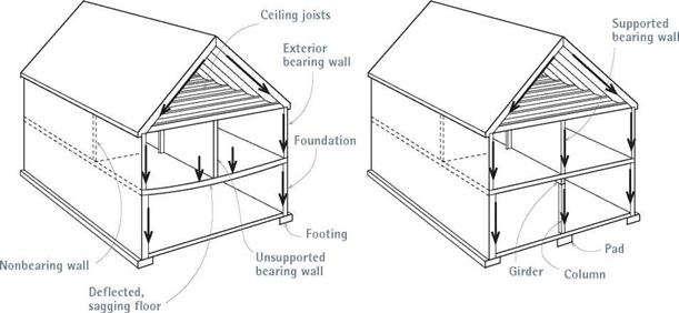
For the best understanding of your house’s structure, start in the basement, where joists and girders are visible, or in an unfinished attic, where rafters and floor joists are frequently exposed. In finished living spaces, wood floors are usually installed perpendicular to joists, so look at flooring-nail patterns. Common sense can be reliable: If the floor slopes down to the base of a wall, there’s a good chance that wall is bearing a load—and may be insufficiently supported.
In most wood-frame houses, bearing walls run perpendicularly to the joists they support, in effect, shortening the distance those joists must span. Bearing walls are usually supported by bearing walls below, on down to the basement, where they will be supported by a girder and posts. However, there are framing eccentricities, especially for additions.
In apartments and row houses, interior walls often aren’t bearing because most apartments are framed with steel girders, and the floors consist
|
of reinforced concrete slabs. In row houses, joists and rafters customarily run the width of the house, between exterior walls. Thus interior walls running parallel to joists or rafters are rarely bearing. Partitions running perpendicularly to framing members were probably not bearing walls originally, but they may have become so if joists were undersize to begin with or if their effective spans were reduced by “remuddlers” cutting into them. In such instances partitions may become bearing walls, and floors may slope toward them.
If a wall is nonbearing, removing it may not cause problems. But if it is bearing, you must first transfer the loads it bears to temporary supports, called shoring, before you can alter it. Similarly, avoid removing any structural buttresses with impunity, such as braces and rafter collar ties. Otherwise unsupported structural elements may sag.
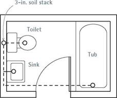
Plumbing fixtures and pipes are usually grouped around a 3-in. or 4-in. soil stack located in a wall near the toilet. Drainpipes are often routed between nearby joists. If the DWV (drainage-waste-vest) system is in decent shape, try not to disturb larger pipes because rerouting them is expensive. Draw fixtures on your plumbing map, and note where main drains emerge in the basement and where vent stacks protrude from the roof.
Supply pipes are rarely a design constraint. That is, because supply pipes are smaller and their water is under pressure, they don’t need to
be pitched, as do waste and drainpipes. In many houses, large vents are concealed within “wet walls” framed out with 2x6s that provide plenty of room for even the biggest pipe. Moreover, drains should slope downward at least!4 in. per foot. Thus a 3-in. drain would need almost an 8 in. height for a 12-ft. horizontal run (3h in. for the exterior diameter of pipe, 3 in. for slope, 1 in. of clearance) and, therefore, would need 2×10 joists, as a minimum. Because cutting 4-in. holes through joists would seriously weaken them, it’s
|
|
Plumbing fixtures are often grouped around a
3- in. or 4-in. soil stack. Because of their size, the soil stack and the main drain it feeds are the most problematic to relocate.


Use these symbols to map your home’s electrical system. Use different-color felt-tip markers to denote different circuits. See p. 234 for more electrical symbols.
easy to see why large drainpipes almost always need to be routed between joists, rather than through them. If the existing joists don’t provide the height needed to run 3-in. or 4-in. drains, it’s possible to build up a platform over an existing floor or to frame out false ceilings below. Yet if such complications present themselves, consider a simpler design.
Heating and cooling systems can also affect design plans, depending on the type of system. The renovator’s primary concern in placing heating and cooling systems is to make sure that pipes and ductwork do not encounter joists, fire-stops, bridging, or other impediments. Modern hydron – ic (hot-water) heating systems are typically fed by %-in. pipe and so can usually be relocated easily; whereas steam heat, supplied by 112-in. to 2-in. pipe, will require planning. By far, forced hot air (FHA) is the most difficult heating system to plan around because the ducts are so bulky. In this case, where space is tight, false walls, floors, and ceilings are commonly employed. But because the hot air is pushed by a fan, ducts do not need to be sloped upward (although this is desirable) to function well. When renovations require the gutting of wall surfaces, vertical duct runs can easily fit between standard 2×4 studs. Flexible insulated duct greatly expands routing options.
Ventilators for bathrooms and appliances are rarely problematic, since exhaust fans draw air from relatively small, isolated areas. By placing
ovens, cooktops, or stoves near exterior walls or beneath a venting bonnet, you can easily route cooking exhaust to the outside.
When mapping a FHA system, note the locations of registers and the furnace. Then intuit the locations of ductwork, using dotted lines to suggest duct runs. In most cases, ducts or hydronic piping will be visible in the basement. For upper-story heat outlets, delivery ducts and pipes generally travel straight up between studs. In general, avoid running ducts within structural walls, because that would require the cutting of wall plates.
Electrical wiring rarely affects design phases unless you intend to move a service panel. Small and flexible, electrical cable is easily routed through walls, floors, and ceilings. Where you don’t want to cut into existing surfaces, or can’t— as with masonry floors—run rigid conduit or track wiring along the surface.
Mapping the electrical system is best done by two people: one standing at the service panel flipping the circuit breakers off and on (or removing fuses from a fused panel), while the other inserts a voltage tester into electrical outlets, as shown in "Using a Voltage Tester,” on p. 235. When the light goes out, you’ve identified the circuit controlling it. (Using cell phones to communicate with each other will save a lot of yelling between floors.) It’s difficult to know exactly where cables are, but by noting where cables enter the panel from floors above and using your map of electrical circuits, you can make an educated guess.
Finally, map electrical safety as best you can (see Chapter 11). In your survey, did you find ungrounded, two-hole receptacles or grounded, three-hole outlets? Is lighting adequate in bathrooms and kitchens? Light switches at the top and bottom of stairs? How about shock protection? Kitchen receptacles within 4 ft. of a sink and all bathroom receptacles must be protected by ground-fault circuit interrupters (GFCIs), which cut off power within f4o second when they detect even a slight leak (4 milliamps to 6 milliamps). Local codes may also specify arc-fault circuit interrupters (AFCIs), which can prevent fires caused by loose or corroded electrical connections, nails puncturing wires, and the like. For more about GFCI and AFCI protection, see Chapter 11.


Leave a reply