FRAMING A DOOR OR WINDOW OPENING
After cutting back interior surfaces to expose the framing in the exterior wall, outline the RO by snapping chalklines across the edges of studs. If you can incorporate existing studs into the new opening—an old stud might become the king stud of the new opening, as shown in the photo on p. 165—you can save time and materials.
To remove old studs within the new opening, use a sledge to rap the bearing wall’s top plate upward, thus creating a small gap above the studs (and old header, if any). That should create enough space to slip in a metal-cutting reciprocating-saw blade and cut through nails holding studs to the top plate. Though sheathing or siding may be nailed to the studs, they should still pull out easily.
Start framing the new opening by toenailing the king stud on both sides, using three 10d nails or four 8d nails top and bottom. Laminate the header package or cut it from 4x stock. (The procedures described here employ terms illustrated in "Stud-Wall Elements,” on p. 155.) Precut the jack studs, and face-nail one to a king stud; lean the second near the other side of the opening. Place one end of the header atop the jack stud in place. Then slide the second jack under the free end of the header. Raise the header by tapping the second jack into place. Or, as an alternative, you can use a screw jack to hold the header flush to the underside of the top plate. Check for level; then measure and cut both jack studs to length.
If there are cripple studs over the header, nail up one jack stud, use a level to establish the height of the jack stud on the second side, and nail it up. Install the header; then cut the cripple studs to length and install them. If you’re framing a window opening, there will also be cripple studs under the sill. So level and install the sill next, using four 8d nails on both sides for toenailing the sill ends to the jack studs. End-nail through the sill into the top of the cripple studs; toenail the bottoms of the cripple studs to the sole plate.
To mark the rough opening outside, cut
through the sheathing and the siding, using a reciprocating saw. Or, if you want to strip most of the siding in the affected area first, drill a hole
is it a Bearing wall?
As noted in "Exploring Your Options," on p. 152, bearing walls and girders usually run parallel to the roof ridge and perpendicular to the joists and rafters they support. And in most two-story houses, joists usually run in the same direction from floor to floor.
Things get tricky, however, when rooms have been added piecemeal and when previous remodelers used nonstandard framing methods. For that, you’ll need to explore. Use an electronic stud-finder or note which way the heating ducts run (usually between joists) to figure out joist direction. If all else fails, go into a closet, pantry, or other inconspicuous location and cut a small hole in the ceiling so you can see which way the joists run.
Finally, nonbearing walls sometimes become bearing walls when homeowners place heavy furniture, book shelves, appliances, or tubs above them. If floors deflect—slope downward—noticeably toward the base of such walls, they’re probably bearing.
through each corner of the RO. Outside, snap chalklines through the four holes. Remove siding within that opening—plus the width of the new exterior casing around all four sides. Nail the sheathing to the edges of the new frame. Finally, run a reciprocating saw along the chalklines to cut sheathing flush to the edges of the RO. Now you’re ready to flash the opening and install the door or window. Chapter 6 will guide you from there.
Bearing-wall replacements should be designed by a structural engineer and executed by a contractor adept at erecting shoring and handling heavy loads in tight spaces. In the two methods presented in the following text, beam-and-post systems replace bearing stud walls. In the first method, the bearing beam is exposed because it supports joists from below. In the second method, the beam is hidden in the ceiling, and joist hangers attach joists to the beam.
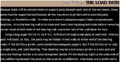
О Once you’ve cut electrical power to the affected area, installed shoring on both sides of the existing bearing wall, and inserted blocking under support post locations, you’re ready to remove the bearing wall and replace it with a new beam. However, if you’re installing a hidden beam, your job will be easier if you leave the old
wall in place a bit longer to steady the joist ends as you cut through them.
Installing an exposed beam is the easier of the two methods. Because ceiling joists sit atop an exposed beam, it’s not necessary to cut the joists—as it is when installing a hidden beam. After removing the bearing wall, snap chalklines on the ceiling to indicate the width of the new beam—say, 4h in. wide for a beam laminated from three 2x10s or 2x12s. Cut out the finish surfaces within this 4h-in.-wide slot so the joists can sit directly on the beam. Chances are, the slot won’t need to be much wider than the width of the top plate of the wall just removed.
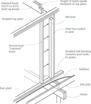
Because the beam extends into end walls, notch the beam ends so they will fit under the end-wall top plates, which may also support joists. Notching ensures that the top of the beam, the top plates, and the bottom of the ceiling joists will be the same height. If end walls have doubled top plates, the notch will be 3 in. to 4 in. deep. Before notching the beam, eyeball it for crown and place it crown up. Before raising the beam, be sure to have blocking under each post to ensure a continuous load path down to the foundation.
A laminated 2×12 beam can weigh 250 lb., so have enough helpers to raise it safely. Once the top of the beam is in place, flush to the underside of the joists above, temporarily support it with plumbed screw jacks or 2x4s cut % in. long and wedged beneath the beam—have workers tack- nail and monitor the 2x4s so they can’t kick out! (Put 2x plates beneath the jacks or the wedged 2x4s to avoid damaging finish flooring.)
Measure from the underside of the new exposed beam to the floor or subfloor. Then cut 4×4 posts Яв in. longer than the height of the opening, and use a sledgehammer to tap them into place. (Ideally, cut posts the exact length; but a little long is preferable to a little short.) Plumb the posts, and install metal connectors such as Simpson Strong-Tie A-23 anchors to secure the post ends to the top and sole plates. Add studs to both sides of each post, as shown in "Supporting an Exposed Beam,” to "capture” it and keep it from moving; nail these studs to the plates and to the 4x4s as well.
![]()

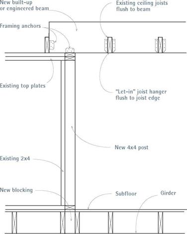
 Installing a hidden beam takes more work than installing an exposed beam but yields a smooth ceiling. To summarize, after erecting stud-wall shoring on both sides of the bearing wall to be replaced, cut all the ceiling joists to create a slot for the hidden beam, assemble the beam on the ground, and then lift it into place. Here, joists will hang from the sides of the beam rather than

![]()
sitting atop it, so the hidden beam will rest on top of end-wall top plates.
Thus install 4×4 posts between the top and the sole plates—and blocking under the posts— before raising the beam. Snap chalklines on the ceiling to indicate the width of the beam plus 4 in. extra on each side so you can slide joist hangers in later. Cut out drywall or plaster within that slot to open up the ceiling and expose joists. After installing shoring, as explained in earlier sections, go up into the attic.
1. Make the attic workspace safe and comfortable. Place 2-in.-thick planks or 58-in. plywood walkways on both sides of the area where you’ll insert the beam. Tack-nail the walkways so they can’t drift. Clamp work lights to the underside of rafters and add ventilation. For necessary ventilation, you may first need to install gable end louvers and buy a fan—especially if it’s summer. If roofing nails protrude from the underside of roof sheathing, wear a hard hat.
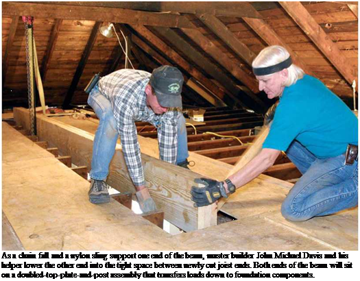
If there’s enough room in the attic, assemble the beam in place and lower it down into the slot you’ll create by cutting back joist ends. However, if you must assemble the beam on the floor below—or if you’re raising an engineered beam— use a nylon web sling and a chain fall (see the photo on p. 53) bolted through the rafters to raise the beam up through the cutout in the ceiling. Angle-brace rafters to keep them from deflecting under the load, and don’t attach a chain fall to rafters that are cracked or already sagging.
2. Snap a chalkline to mark the beam location onto the top edges of joists. Snap a first line to mark the centerline of the beam. Then measure out half the beam width plus 58 in. on both sides, and snap chalklines to indicate cut-lines on the joists. Using a square, extend these lines down the face of each joist. Use vivid chalk so the marks will be visible.
Because thin reciprocating-saw blades wander, use a circular saw to ensure square cuts across joists. It’s hard to see the cut-line of a saw you’re lowering between two joists, so clamp a framing square to each joist to act as a guide for the saw shoe. Some renovators prefer a small chainsaw for this operation, but hitting a single hidden nail in a joist can snap a chainsaw blade and send it flying at you. Whatever you use to cut the joists, wear hearing and eye protection and, ideally, have a similarly protected helper nearby shining a light into the cut area.
3. Get help to raise the beam one end at a time. If your cuts are accurate, you should be able to raise the beam between the severed joists and onto the top plate of one end wall and then the other. But, invariably, the beam gets hung up on something. Here, a chain fall is invaluable because it allows you to raise and lower one end of the beam numerous times without killing your back or exhausting your crew.
When the first end of the beam is up, nail cleats to both sides of the beam so it can’t slip back through the opening as you raise the other end. Raise and position the other end of the beam atop the other end wall and directly over

 Before attaching joist hangers, make a single pass of a power plane across the underside of each joist end, where it abuts the new beam. The planed area, roughly the width and thickness of a joist hanger "stirrup," ensures that the joist hangers will be flush to the bottom of the joists and the beam and that the patched ceiling will be evenly flat.
1111
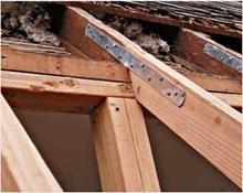
Steel connectors are an important part of renovation carpentry, often joining new and old framing members.
Straps such as Simpson Strong – Tie LSTA strap ties are frequently used where wall plates are cut, at wall intersections, and as ridge ties.
Pros often use them to splice new rafter tails to existing rafters, to replace sections that rotted at the wall plate. After cutting rafter tails at the correct angle, toenail them to the top plate and use 12-in. or 18-in. strap ties to tie new tails to the old rafters. After the sheathing is nailed on, such reinforced rafter tails will stay in line indefinitely.
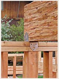
The 4×14 Parallam beam sitting atop a 2×4 top plate at right is much like the hidden beam discussed in "Installing a Hidden Beam" in the text. In the old days, beams of this size would have been merely toenailed to top plates.
So the Simpson BC4 post cap now specified by engineers is quite an improvement. It’s simple to install and strong enough to resist uplift and lateral movement. Note, too, the 4×4 post directly under the beam—it’s part of the load path that goes all the way down to the foundation.


Leave a reply