 Storm-water calculations stump some plumbers. I think that the problem for some plumbers is computing the amount of water accumulated due to structures on roofs. For example, if a roof has an enclosed stairway system, the walls and roof of the stairway have to be factored into the equation for what is required in rainfall drainage. Some plumbers find doing the math for roof drains, rain leaders, and other storm piping to be intimidating. Given the proper charts and tables, the job is not really too difficult.
 I used to teach code classes for plumbers who were preparing to take their licensing tests. After teaching the class for a while, I noticed some common elements from class to class. One common thread that seemed to run from class to class was a fear of doing storm-water calculations. I came to expect the classes to be intimidated by what I didn’t perceive to be any big deal. Knowing how to size a drainage system for storm water is a requirement for licensing where I live and work, so the people in the class had to address their fears. This, however, was true only of those going for their master’s license. Oddly enough, once they were given an example or two of how the work is done, most of them didn’t have any problem with their calculations.
111

FIGURE 6.1 ■ Rainwater code requirements. (Courtesy of Uniform Plumbing Code)
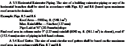
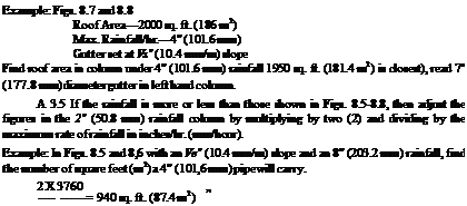
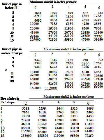
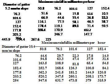
I could create some examples for you to work with here, but I won’t. Why? Because two of the major codes already offer sample exercises in their codebooks, and the two codes have agreed to allow me to use their examples for this chapter’s tutorial. So, what I’m going to do is show you actual excerpts from two codebooks. One of the codes is the Uniform Plumbing Code. The other is the Standard Plumbing Code, or as some people call it, the Southern Plumbing Code. I will let you look over the examples, one at a time, and then I will comment on them, pointing out some of the areas that may appear a little tricky. Let’s start with the example provided in the Uniform Plumbing Code. Please refer to Figures 6.1 through 6.8 for code requirements and a sizing example for rainwater systems. I want you to keep in mind that books age
|
(c) Roof drains, overflow drains, and rainwater piping installed within the construction of the building shall be tested in conformity with the provisions of this Code for testing drain, waste, and vent systems.
Part В
Roof Drains
A 2 Materials: Roof drains shall be of cast iron, copper, lead, or other corrosion resisting material.
A 2.1 Strainers:
(a) Roof drains shall be equipped with strainers extending not less than four (4) inches (101.6 mm) above the surface of the roof immediately adjacent to the drain. Strainers shall have minimum inlet area one and one-half (IV2) times the pipe to which it is connected.
(b) Roof deck strainers for use on sun decks, parking decks, and similar occupied areas may be of an approved flat-surface type which is level with the deck. Such drains shall have an inlet area not less than two (2) times the area of the pipe to which the drain is connected.
(c) Roof drains passing through the roof into the interior of a building shall be made watertight at the roof line by the use of a suitable flashing material.
PartC
Sizing of Rainwater Piping
A 3.1 Vertical rainwater piping shall be sized in accordance with Fig. 8.3. Figure 8.3 is based upon maximum inches (mm) of rainfall per hour falling upon a given roof area in square feet (m2). Consult local rainfall figures to determine maximum rainfall per hour.
A 3.2 Vertical Wall Areas. Where vertical walls project above a roof so as to permit storm water to drain to the roof area below the adjacent roof area may be computed from Fig. 8.3 as follows:
(a) For one (1) wall—add fifty (50) percent of the wall area to the roof area figures.
(b) For two (2) adjacent walls—add thirty-five (35) percent of the total wall areas.
(c) Two (2) walls opposite of same heights—add no additional area.
(d) Two (2) walls opposite of differing heights—add fifty (50) percent of wall area above top of lower wall.
(e) Walls on three (3) sides—add fifty (50) percent of area of the inner wall below the top of the lowest wall, plus allowance for area of wall above top of lowest wall per (b) and (d).
(f) Walls on four (4) sides—no allowance for all areas below top of lowest wall – add for areas above top of lowest wall per (a), (b), (d), and (e).
|
|
|
|
|
and the illustrations here may not be up to speed with your current, local code. Check you own code requirements and use the tables here as examples of how to use what you have.
Now that you’ve had a chance to look over the illustrations, you may have a solid understanding of how to size a rainwater system. If you do, that’s great. But, maybe you have a little confusion that needs to be cleared up. Let me go over a few of the points that some plumbers from my classes have had trouble with. Start by looking at Figure 6.2, part C. In category A 3.2 of Figure 6.2, I want you to look at letter A. The code tells you to figure 50 percent of
|
|
a single wall for additional rainwater. So, if the wall is 10 feet long and 10 feet tall, its total area would be 100 square feet. This is determined by multiplying the width by the height. In this case, we would add 50 square feet of area to our working numbers to apply to the sizing chart.
Now look at the ruling in letter B. It says that if you have two adjacent walls, you must add 35-percent of their combined area to the equation.
|
Sizing of Roof Drains and Rainwater Piping for Varying Rainfall Quantities are Horizontal Projected Roof Areas in Square Feet
|
Rain fall
|
|
Size of drain or
|
leader in
|
inches*
|
|
|
in inches
|
2
|
3
|
4
|
5
|
6
|
8
|
|
1
|
2880
|
8800
|
18400
|
34600
|
54000
|
116000
|
|
2
|
1440
|
4400
|
9200
|
17300
|
27000
|
58000
|
|
3
|
960
|
2930
|
6130
|
11530
|
17995
|
38660
|
|
4
|
720
|
2200
|
4600
|
8650
|
13500
|
29000
|
|
5
|
575
|
1760
|
3680
|
6920
|
10800
|
23200
|
|
6
|
480
|
1470
|
3070
|
5765
|
9000
|
19315
|
|
7
|
410
|
1260
|
2630
|
4945
|
7715
|
16570
|
|
8
|
360
|
1100
|
2300
|
4325
|
6750
|
14500
|
|
9
|
320
|
980
|
2045
|
3845
|
6000
|
12890
|
|
10
|
290
|
880
|
1840
|
3460
|
5400
|
11600
|
|
11
|
260
|
800
|
1675
|
3145
|
4910
|
10545
|
|
12
|
240
|
730
|
1530
|
2880
|
4500
|
9660
|
|
|
_ . . Size of drain or leader in millimeters*
|
in mm
|
50.8
|
76.2
|
101.6
|
127
|
152.4
|
203.2
|
|
25.4
|
267.6
|
817.5
|
1709.4
|
3214.3
|
5016.6
|
10776.4
|
|
50.8
|
133.8
|
408.8
|
854.7
|
1607.2
|
2508.3
|
5388.2
|
|
76.2
|
89.2
|
272.2
|
569.5
|
1071,1
|
1671.7
|
3591.5
|
|
101.6
|
66.9
|
204.4
|
427.3
|
803.6
|
1254.2
|
2694.1
|
|
127
|
53.4
|
163.5
|
341.8
|
642.9
|
1003.3
|
2155.3
|
|
152.4
|
44.6
|
136.6
|
285.2
|
535.6
|
836.1
|
1794.4
|
|
177.8
|
38.1
|
117.1
|
244.3
|
459.4
|
716.7
|
1539.4
|
|
203.2
|
33.4
|
102.2
|
213.7
|
401.8
|
627.1
|
1347.1
|
|
228.6
|
29.7
|
91
|
190
|
357.2
|
557.4
|
1197.5
|
|
254
|
26.9
|
81.8
|
170.9
|
321.4
|
501.7
|
1077.6
|
|
279.4
|
24.2
|
74.3
|
155.6
|
292.2
|
456.1
|
979.6
|
|
304.8
|
22.3
|
67.8
|
142.1
|
267.6
|
418.1
|
897.4
|
|
 |
 |
Assuming that each wall was 10 feet by 10 feet, we would have a total of 200 square feet. 35 percent of 200 square feet is 70 square feet. See how easy this is? In the rulings identified by the letter C, you can see that no additional square footage is added when you have two walls that are opposite of each other and that are the same size. But, letter D offers another ruling. Assume that you have two walls opposite of each other. one of the walls is 10 feet by 10 feet. The other is 10 feet by 15 feet. How much area do you add? One wall is 5 feet taller than the other and 10 feet wide. This amounts to a total area of 50 square feet in differing size for computation purposes. Now all you have to do is divide the difference in half for your working number, which in this case would be 25 square feet. If you pay attention, the code does most of the work for you.
|
Size of Horizontal Rainwater Piping
|
|
 |
|
Size of Horizontal Rainwater Piping
|
Size of pipe in mm 10.4 mm/m slope
|
Maximum rainfall
|
in millimeters per
|
hour
|
|
50.8
|
76.2
|
101.6
|
127
|
152.4
|
|
76.2
|
152.7
|
101.8
|
76.4
|
61
|
50.9
|
|
101.6
|
349.3
|
232.8
|
174.7
|
139.7
|
116.4
|
|
127
|
620.6
|
413.7
|
310.3
|
248.2
|
206.9
|
|
152.4
|
994
|
662.7
|
497
|
397.6
|
331.3
|
|
203.2
|
2136.7
|
1424.2
|
1068.4
|
854.7
|
706
|
|
254
|
3846.1
|
2564
|
1923
|
1540.3
|
1282
|
|
279.4
|
6187.1
|
4124.8
|
3093.6
|
2475.8
|
2062.4
|
|
381
|
10126.1
|
6763.1
|
5527.6
|
4422
|
3683.5
|
|
|
Size of pipe in mm 20.9 mm/m slope
|
Maximum rainfall in millimeters per hour
|
|
50.8
|
76.2
|
101.6
|
127
|
152.4
|
|
76.2
|
215.5
|
143.6
|
107.8
|
86.2
|
71.8
|
|
101.6
|
492.4
|
328.2
|
246.2
|
197
|
164.1
|
|
127
|
877
|
584.1
|
438.5
|
350.8
|
292.3
|
|
152.4
|
1402.8
|
935.1
|
701.4
|
561.1
|
467.6
|
|
203.2
|
3028.5
|
2019
|
1514.3
|
1211.4
|
1009.5
|
|
254
|
5425.4
|
3618.5
|
2712.7
|
2169.2
|
1806.9
|
|
304.8
|
8732.6
|
5815.5
|
4366.3
|
3493
|
2912.4
|
|
381
|
15607.2
|
10404.8
|
7803.6
|
6247.5
|
5205.4
|
|
Size of pipe in mm 41.7 mm/m slope
|
Maximum rainfall
|
in millimeters per hour
|
|
50.8
|
76.2
|
101.6
|
127
|
152.4
|
|
76.2
|
305.5
|
213.2
|
152.7
|
121.7
|
101.8
|
|
101.6
|
698.6
|
465.4
|
349.3
|
279.6
|
232.3
|
|
127
|
1241.1
|
826.8
|
620.6
|
494.2
|
413.4
|
|
152.4
|
1988.1
|
1272.3
|
994
|
797.1
|
663.3
|
|
203.2
|
4274.4
|
2847.4
|
2136.7
|
1709.4
|
1423.2
|
|
254
|
7692.1
|
5128.1
|
3846.1
|
3079.6
|
2564
|
|
304.8
|
12374.3
|
8249.5
|
6187.1
|
4942.3
|
4124.8
|
|
381
|
22110.2
|
14752.5
|
11055.1
|
8853.4
|
7362.3
|
|
|
|
Maximum rainfall in inches per hour
|
Уїв" slope
|
2
|
3
|
4
|
5
|
6
|
|
3
|
340
|
226
|
170
|
136
|
113
|
|
4
|
720
|
480
|
*360
|
288
|
240
|
|
5
|
1250
|
834
|
625
|
500
|
416
|
|
6
|
1920
|
1280
|
960
|
768
|
640
|
|
7
|
2760
|
1840
|
1380
|
1100
|
918
|
|
8
|
3980
|
2655
|
1990
|
1590
|
1325
|
|
10
|
7200
|
4800
|
3600
|
2880
|
2400
|
|
Diameter of gutter Vb" slope
|
Maximum rainfall in inches per
|
hour
|
|
2
|
3
|
4
|
5
|
6
|
|
3
|
480
|
320
|
240
|
192
|
160
|
|
4
|
1020
|
681
|
510
|
408
|
340
|
|
5
|
1760
|
1172
|
880
|
704
|
587
|
|
6
|
2720
|
1815
|
1360
|
1085
|
905
|
|
7
|
3900
|
2600
|
1950
|
1560
|
1300
|
|
8
|
5600
|
3740
|
2800
|
2240
|
1870
|
|
10
|
10200
|
6800
|
5100
|
4080
|
3400
|
|
Diameter of gutter slope
|
Maximum rainfall in inches per
|
hour
|
|
2
|
3
|
4
|
5
|
6
|
|
3
|
680
|
454
|
340
|
272
|
226
|
|
4
|
1440
|
960
|
720
|
576
|
480
|
|
5
|
2500
|
1668
|
1250
|
1000
|
834
|
|
6
|
3840
|
2560
|
1920
|
1536
|
1280
|
|
7
|
5520
|
3680
|
2760
|
2205
|
1840
|
|
8
|
7960
|
5310
|
3980
|
3180
|
2655
|
|
10
|
14400
|
9600
|
7200
|
5750
|
4800
|
|
Diameter of gutter W slope
|
Maximum rainfall in inches per
|
hour
|
|
2
|
3
|
4
|
5
|
6
|
|
3
|
960
|
640
|
480
|
384
|
320
|
|
4
|
2040
|
1360
|
1020
|
816
|
680
|
|
5
|
3540
|
2360
|
1770
|
1415
|
1180
|
|
6
|
5540
|
3695
|
2770
|
2220
|
1850
|
|
7
|
7800
|
5200
|
3900
|
3120
|
2600
|
|
8
|
11200
|
7460
|
5600
|
4480
|
3730
|
|
10
|
20000
|
13330
|
10000
|
8000
|
6660
|
|
|
|
|
 |
|
Diameter of gutter 20.9 mm/m slope
|
Maximum rainfall
|
in millimeters per hour
|
|
50.8
|
76.2
|
101.6
|
127
|
152.4
|
|
76.2
|
63.2
|
42.2
|
31.6
|
25.3
|
21
|
|
101.6
|
133.8
|
89.2
|
66.9
|
53.5
|
44.6
|
|
127
|
232.3
|
155
|
116.1
|
92.9
|
77.5
|
|
152.4
|
356.7
|
237.8
|
178.4
|
142.7
|
118.9
|
|
177.8
|
512.8
|
341.9
|
256.4
|
204.9
|
170.9
|
|
203.2
|
739.5
|
493.3
|
369.7
|
295.4
|
246.7
|
|
254
|
133.8
|
891.8
|
668.9
|
534.2
|
445.9
|
|
|
|
Diameter of gutter 41.7 mm/m slope
|
Maximum rainfall
|
in millimeters per
|
hour
|
|
50.8
|
76.2
|
101.6
|
127
|
152.4
|
|
76.2
|
89.2
|
59.5
|
44.6
|
35.7
|
29.7
|
|
101.6
|
189.5
|
126.3
|
94.8
|
75.8
|
63.2
|
|
127
|
328.9
|
219.2
|
164.4
|
131.5
|
109.6
|
|
152.4
|
514.7
|
343.3
|
257.3
|
206.2
|
171.9
|
|
177.8
|
724.6
|
483.1
|
362.3
|
289.9
|
241.4
|
|
203.2
|
1040.5
|
693
|
520.2
|
416.2
|
346.5
|
|
254
|
1858
|
1238.4
|
929
|
743.2
|
618.7
|
|
|
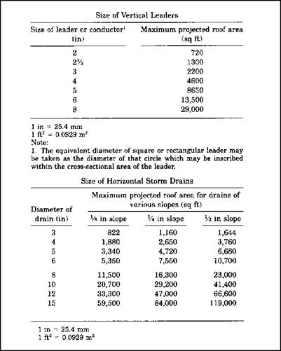
Now, let’s look at the example given by the Standard Plumbing Code (Figs. 6.9 to 6.15). Some plumbing codes have recently joined forces to create a cohesive code. Most of this book is based on the International Plumbing Code, but there are others and there are combinations. Keep in mind that every code jurisdiction can create their own amendments to the code, so you must refer to your local, enforceable code to be sure that you are on track with local requirements.
|
|
|
The sizing example you have just seen is a good, step-by-step example of how to size a drainage system for storm water. You’ve seen actual code examples and rulings, but remember that these codes are subject to change and may not be the codes being used in your area. Consult your local plumbing code for current, applicable code requirements in your region.
|
|
|
SECONDARY (EMERGENCY) ROOF DRAINS Secondary Drainage Required
Secondary (emergency) roof drains or scuppers shall be provided where the roof perimeter construction extends above the roof in such a manner that water would be entrapped should the primary drains allow buildup for any reason.
Separate Systems Required
Secondary roof drain systems shall have piping and point of discharge separate from the primary system. Discharge shall be above grade in a location which would normally be observed by the building occupants or maintenance personnel.
Maximum Rainfall Rate for Secondary Drains
Secondary (emergency) roof drain systems or scuppers shall be sized based on the flow rate caused by the 100 year 15 minute precipitation as indicated in Fig. 8.12. The flow through the primary system shall not be considered when sizing the secondary roof drain system.
CONVERSION OF ROOF AREA
General
Where roof drainage is connected to a combined sewer, the drainage area may be converted to equivalent fixture unit loads.
Less Than 256 Fixture Units
When the total fixture unit load on the combined drain is less than 256 fixture units, the equivalent drainage area in horizontal projection shall be taken as 1000 sq ft (92.9 m2).
Greater Than 256 Fixture Units
When the total fixture unit load exceeds 256 fixture units, each additional fixture unit shall be considered the equivalent of 3.9 ft2 (0.3623 m2) of drainage area.
Rainfall Other Than 4 Inches (102 mm) Per Hour
If the rainfall to be provided for is more or less than 4 inches (102 mm) per hour, the 1,000 sq ft (92.9 m2) equivalent in 1110.2 and the 3.9 sq ft (0.3623 m2) in 1110.3 shall be adjusted by multiplying by 4 and dividing by the rainfall per hour to be provided for.
VALUES FOR CONTINUOUS FLOW
Where there is a continuous or semicontinuous discharge into the building storm drain or building storm sewer, as from a pump, ejector, air conditioning plant, or similar device, each gallon per minute of such discharge shall be computed as being equivalent to 24 sq ft (2.23 m2) of roof area, based upon a 4-inch (102 mm) rainfall.
|
|
|
|
|
BACKWATER VALVES
Fixture Branches
Backwater valves shall be installed in the branch of the building drain which receives only the discharge from fixtures located within such branch and shall be located below grade.
Material
Backwater valves shall have all bearing parts of corrosion resistant material. Backwater valves shall comply with ANSI/ASME A112.14.1 or CSA B181.1, CSAB181.2.
Seal
Backwater valves shall be so constructed as to insure a mechanical seal against backflow.
Diameter
Backwater valves, when fully opened, shall have a capacity not less than that of the pipes in which they are installed.
Location
Backwater valves shall be so installed to be accessible for service and repair. APPENDIX REFERENCES
Additional provisions for storm drainage are found in Appendix В-Roof Drain Sizing Method. These provisions are applicable only where specifically included in the adopting ordinance.
|
|
|
|
|
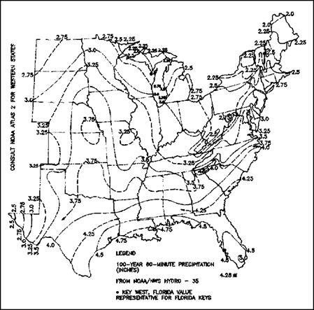
FIGURE 6.11 ■ Rainfall rates for primary roof drains (in/hr). (Courtesy of Standard Plumbing Code)
|
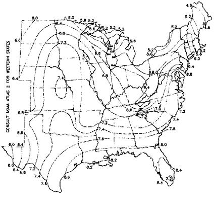 FIGURE 6.12 ■ Rainfall rates for secondary roof drains (in/hr). (Courtesy of Standard Plumbing Code)
 Storm-water calculations stump some plumbers. I think that the problem for some plumbers is computing the amount of water accumulated due to structures on roofs. For example, if a roof has an enclosed stairway system, the walls and roof of the stairway have to be factored into the equation for what is required in rainfall drainage. Some plumbers find doing the math for roof drains, rain leaders, and other storm piping to be intimidating. Given the proper charts and tables, the job is not really too difficult.
 I used to teach code classes for plumbers who were preparing to take their licensing tests. After teaching the class for a while, I noticed some common elements from class to class. One common thread that seemed to run from class to class was a fear of doing storm-water calculations. I came to expect the classes to be intimidated by what I didn’t perceive to be any big deal. Knowing how to size a drainage system for storm water is a requirement for licensing where I live and work, so the people in the class had to address their fears. This, however, was true only of those going for their master’s license. Oddly enough, once they were given an example or two of how the work is done, most of them didn’t have any problem with their calculations.
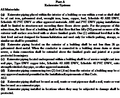


 FIGURE 6.12 ■ Rainfall rates for secondary roof drains (in/hr). (Courtesy of Standard Plumbing Code)


Leave a reply