Piping color codes are used when utility companies stake out piping locations. For example, a yellow flag generally indicates one of the following types of pipe:
■ Oil
■ Steam
■ Gas
■ Petroleum
When you encounter a blue flag that indicates the location of piping below ground, the type of piping that you are probably dealing with is one of the following:
■ Potable Water
■ Irrigation Water
■ Slurry Pipes
|
Diameter
|
Service
|
Extra heavy
|
|
(inches)
|
weight (lb)
|
weight (lb)
|
|
Double hub,
|
2
|
21
|
26
|
|
5-ft lengths
|
3
|
31
|
47
|
|
4
|
42
|
63
|
|
5
|
54
|
78
|
|
6
|
68
|
100
|
|
8
|
105
|
157
|
|
10
|
150
|
225
|
|
Double hub,
|
2
|
11
|
14
|
|
30-ft length
|
3
|
17
|
26
|
|
4
|
23
|
33
|
|
Single hub,
|
2
|
20
|
25
|
|
5-ft lengths
|
3
|
30
|
45
|
|
4
|
40
|
60
|
|
5
|
52
|
75
|
|
6
|
65
|
95
|
|
8
|
100
|
150
|
|
10
|
145
|
215
|
|
Single hub,
|
2
|
38
|
43
|
|
10-ft lengths
|
3
|
56
|
83
|
|
4
|
75
|
108
|
|
5
|
98
|
133
|
|
6
|
124
|
160
|
|
8
|
185
|
265
|
|
10
|
270
|
400
|
|
No-hub pipe,
|
lVfc
|
27
|
|
|
10-ft lengths
|
2
|
38
|
|
|
3
|
54
|
|
|
4
|
74
|
|
|
5
|
95
|
|
|
6
|
118
|
|
|
8
|
180
|
|
FIGURE 11.25 ■ Weight of cast-iron pipe. (Courtesy of McGraw-Hill)
Green flags tend to mark the locations of sewers and drain lines. You can never count on the colors to be right and you should always check with the flagging company to know what types of pipes you may be dealing with, but the above examples are common choices when color-coded flags are used. Now, let’s go to Chapter 12 and see how you can troubleshoot jobs by using tables and common sense for fast solutions to serious problems.
|
Nominal pipe size (inches)
|
Outside
diameter
(inches)
|
Inside
diameter
(inches)
|
Wall
thickness
(inches)
|
|
‘/2
|
0.840
|
0.750
|
0.045
|
|
%
|
1.050
|
0.940
|
0.055
|
|
1
|
1.315
|
1.195
|
0.060
|
|
llA
|
1.660
|
1.520
|
0.070
|
|
1У2
|
1.900
|
1.740
|
0.080
|
|
2
|
2.375
|
2.175
|
0.100
|
|
2V2
|
2.875
|
2.635
|
0.120
|
|
3
|
3,500
|
3.220
|
0.140
|
|
4
|
4.500
|
4.110
|
0.195
|
FIGURE 11.26 ■ Polyvinyl Chloride Plastic Pipe (PVC). (Courtesy of McGraw-Hill)
This page intentionally left blank.
|
Figures 12.1 through 12.27 provide useful tables to help you in troubleshooting problems.
|
|
|
|
|
1. What well conditions might possibly limit the capacity of the pump?
2. How does the diameter of a cased deep well and pumping level of the water affect the capacity?
3. If there are no limiting factors, how is capacity determined?
4. What is suction?
|
|
|
The rate of flow from the source of supply, the diameter of a cased deep well, and the pumping level of the water in a cased deep well.
They limit the size pumping equipment which can be used.
By the maximum number of outlets or faucets likely to be in use at the same time.
A partial vacuum, created in the suction chamber of the pump, obtained by removing pressure due to atmosphere, thereby allowing greater pressure outside to force something (air, gas, water) into the container.
The atmosphere surrounding the earth presses against the earth and all objects on it, producing what we call atmospheric pressure.
This pressure varies with elevation or altitude. It is greatest at sea level (14.7 pounds per square inch) and gradually decreases as elevation above sea level is increased. The rate is approximately 1 foot per 100 feet of elevation.
Since suction lift is actually that height to which atmospheric pressure will force water into a vacuum, theoretically we can use the maximum amount of this pressure 14.7 pounds per square inch at sea level which will raise water 33.9 feet. From this, we obtain the conversion factor of 1 pound per square inch of pressure equals 2.31-feet head.
The resistance of the suction pipe walls to the flow of water uses up part of the work which can be done by atmospheric pressure. Therefore, the amount of loss due to friction in the suction pipe must be added to the vertical elevation which must be overcome, and the total of the two must not exceed 25 feet at sea level. This 25 feet must be reduced 1 foot for every 1000-feet elevation above sea level, which corrects for a lessened atmospheric pressure with increased elevation.
|
|
|
5. What is atmospheric pressure?
|
|
|
6. How much is the pressure due to atmosphere?
|
|
|
7. What is maximum theoretical suction lift?
|
|
|
8. How does friction loss affect suction conditions?
|
|

|
9. When and why do we use a deep – well jet pump?
|
|
|
The resistance of the suction pipe walls to below the pump because this is the maximum practical suction lift which can be obtained with a shallow-well pump at sea level.
A pump with all necessary accessories, fittings, etc., necessary for its completely automatic operation.
It is used on the end of a suction pipe to prevent the water in the system from running back into the source of supply when the pump isn’t operating.
|
|
|
10. What do we mean by water systems?
11. What is the purpose of a foot value?
|
|
|
12. Name the two basic parts of a jet assembly.
13. What is the function of the nozzle?
|
|
|
|
|
The nozzle converts the pressure of the driving water into velocity. The velocity thus created causes a vacuum in the jet assembly or suction chamber.
The diffuser converts the velocity from the nozzle back into pressure.
That water which is supplied under pressure to drive the jet.
The driving water is continuously recirculated in a closed system.
The centrifugal pump provides the energy to circulate the driving water. It also boosts the pressure of the discharged capacity.
Bolted to the casing of the centrifugal pump.
|
|
|
14. What is the purpose of the diffuser?
15. What do we mean by “driving water’?
16. What is the source of the driving water?
17. What is the purpose of the centrifugal pump?
|
|
|
18. Where is the jet assembly usually located in a shallow-well jet system?
19. What is the principal factor which determines if a shallow – well jet system can be used?
20. When is a deep-well jet system used?
21. Can a foot valve be omitted from a deep-well jet system? Why or why not?
|
|
|
|
|
When the total suction sift exceeds that which can be overcome by atmospheric pressure.
No, because there are no valves in the jet assembly, and the foot valve is necessary to hold water in the system when it is primed. Also, when the centrifugal pump isn’t running, the foot valve prevents the water from running back into the well.
|
|
|
FIGURE 12.1 ■ (Continued) Questions and answers about pumps. (Courtesy of McGraw-Hill)
|
|

|
22. What is the function of a check valve in the top of a submersible pump?
23. A submersible pump is made up of two basic parts. What are they?
24. Why did the name submersible pump come into being?
25. Can a submersible pump be installed in a 2-inch well?
|
|
|
To hold the pressure in the line when the pump isn’t running.
|
|
|
|
|
Because the whole unit, pump and motor, is designed to be operated under water.
No, they require a 4-inch well or larger for most domestic use. Larger pumps with larger capacities require 6-inch wells or larger.
Impeller, diffuser, and bowl.
|
|
|
26. A stage in a submersible pump is made up of three parts. What are they?
27. Does a submersible pump have only one pipe connection?
28. What are two reasons we should always consider using a submersible first?
29. The amount of pressure a pump is capable of making is controlled by what?
30. What do the width of an impeller and guide vane control?
|
|
|
|
|
It will pump more water at higher pressure with less horsepower. It also has easier installation.
|
|
|
The diameter of the impeller.
|
|
|
The amount of water or capacity the pump is capable of pumping.
|
|
|
Motor does not start
|
Cause of trouble
|
Checking procedure
|
Corrective action
|
|
No power or incorrect voltage.
|
Using voltmeter, check the line terminals. Voltage must be ± 10% of rated voltage.
|
Contact power company if voltage is incorrect.
|
|
Fuses blown or circuit fuse breakers tripped.
|
Check fuses for recommended size and check for loose, dirty, or corroded connections in fuse receptacle. Check for tripped circuit breaker.
|
Replace with proper or reset circuit breaker.
|
|
Defective pressure switch.
|
Check voltage at contact points. Improper contact of switch points can cause voltage less than line voltage.
|
Replace pressure switch or clean points.
|
|
Control box malfunction.
|
For detailed procedure, see***
|
Repair or replace.
|
|
Defective wiring.
|
Check for loose or corroded connections. Check motor lead terminals with voltmeter for power.
|
Correct faulty wiring or connections.
|
|
Bound pump.
|
Locked rotor conditions can result from misalignment between pump and motor or a sand bound pump. Amp readings 3 to 6 times higher than normal will be indicated.
|
If pump will not start with several trials, it must be pulled and the cause corrected. New installations should always be run without turning off until water clears,
|
|
Defective cable or motor.
|
|
Repair or replace.
|
|
Motor starts too often
|
|
Pressure switch.
|
Check setting on pressure switch and examine for defects.
|
Reset limit or replace switch.
|
|
Check valve, stuck open.
|
Damaged or defective check valve will not hold pressure.
|
Replace if defective.
|
|
Waterlogged tank (air supply).
|
Check air-charging system for proper operation.
|
Clean or replace.
|
|
Leak in system.
|
Check system for leaks.
|
Replace damaged pipes or repair leaks.
|
SOURCE: A. Y. McDonald Manufacturing Co.
|
FIGURE 12.2 ■ Troubleshooting motors. (Courtesy of McGraw-Hill)
|
Motor runs continuously
|
Causes of trouble
|
Checking procedure
|
Corrective action
|
|
Pressure switch.
|
Switch contacts may be “welded” in closed position. Pressure switch may be set too high.
|
Clean contacts, replace switch, or readjust setting.
|
|
Low-level well.
|
Pump may exceed well capacity. Shut off pump, wait for well to recover. Check static and drawdown level from well head.
|
Throttle pump output or reset pump to lower level. Do not lower if sand may clog pump.
|
|
Leak in system.
|
Check system for leaks.
|
Replace damaged pipes or repair leaks.
|
|
Worn pump.
|
Symptoms of worn pump are similar to that of drop pipe leak or low water level in well. Reduce pressure switch setting. If pump shuts off, worn parts may be at fault. Sand is usually present in tank.
|
Pull pump and replace worn impellers, casing, or other close fitting parts.
|
|
Loose or broken motor shaft.
|
No or little water will be delivered if coupling between motor and pump shaft is loose or if a jammed pump has caused the motor shaft to shear off.
|
Check for damaged shafts if coupling is loose, and replace worn or defective units.
|
|
Pump screen blocked.
|
Restricted flow may indicate a clogged intake screen on pump. Pump may be installed in mud or sand.
|
Clean screen and reset at less depth. It may be necessary to clean well.
|
|
Check valve stuck closed.
|
No water will be delivered if check valve is in closed position.
|
Replace if defective.
|
|
Control box malfunction.
|
|
Repair or replace.
|
|
Motor runs but overload protector tips
|
|
Incorrect voltage.
|
Using voltmeter, check the line terminals. Voltage must be within ± 10% of rated voltage.
|
Contact power company if voltage is incorrect.
|
|
Overheated protectors.
|
Direct sunlight or other heat source can make control box hot, causing protectors to trip. The box must not be hot to touch.
|
Shade box, provide ventilation, or move box away from heat source.
|
|
Defective control box.
|
|
Repair or replace.
|
|
Defective motor or cable.
|
|
Repair or replace.
|
|
Worn pump or motor.
|
|
Replace pump and/or motor.
|
source: A. Y. McDonald Manufacturing Co,
|
|
Cable size
|
Resistance
|
|
14
|
0.5150
|
|
12
|
0.3238
|
|
10
|
0.2036
|
|
8
|
0.1281
|
|
6
|
0.08056
|
|
4
|
0.0506
|
|
2
|
0.0318
|
FIGURE 12.4 ■ Resistance of electrical wire.
(Courtesy of McGraw-Hill)
|
Motor does not start
Checking procedure
Using voltmeter check the line terminals Voltage must be ± 10% of rated voltage.
Check fuses for recommended size and check for loose, dirty or corroded connections in fuse receptacle. Check for tripped circuit breaker.
Check voltage at contact points. Improper contact of switch points can cause voltage less than line voltage.
Check for loose or corroded connections. Check motor lead terminals with voltmeter for power.
Locked rotor conditions can result from misalignment between pump and motor or a sand bound pump. Amp readings 3 to 6 times higher than normal will be indicated.
|
|
|
Cause of trouble
A. No power or incorrect voltage.
|
|
|
Correction action
Contact power company if voltage is incorrect.
Replace with proper fuse or reset circuit breaker.
|
|
|
B. Fuses blown or circuit breakers tripped.
|
|
|
Replace pressure switch or clean points.
Repair or replace.
Correct faulty wiring or connections.
|
|
|
C. Defective pressure switch.
|
|
|
D. Control box malfunction.
E. Defective wiring.
|
|
|
If pump will not start with several trials it must be pulled and the cause corrected. New installations should always be run without turning off until water clears.
Repair or replace.
|
|
|
|
 |
|
Motor starts too often
Check setting on pressure switch and examine for defects.
Damaged or defective check valve will not hold pressure.
Check air charging system for proper operation.
Check system for leaks.
|
|
|
Reset limit or replace switch.
Replace if defective.
|
|
|
|
|
Replace damaged pipes or repair leaks.
|
|

|
Motor runs continuously
Checking procedure
Switch contacts may be “welded” in closed position. Pressure switch may be set too high.
Pump may exceed well capacity. Shut off pump, wait for well to recover. Check static and drawdown level from well head.
Check system for leaks.
Symptoms of worn pump are similar to those of drop pipe leak or low water level in well. Reduce pressure switch setting. If pump shuts off, worn parts may be at fault. Sand is usually present in tank.
No or little water will be delivered if coupling between motor and pump shaft is loose or if a jammed pump has caused the motor shaft to shear off.
Restricted flow may indicate a clogged intake screen on pump. Pump may be installed in mud or sand.
No water will be delivered if check valve is in closed position.
|
|
|
Cause of trouble A. Pressure switch.
|
|
|
Correction action
Clean contacts replace switch, or readjust setting.
Throttle pump output or reset pump to lower level. Do not lower if sand may clog pump.
Replace damaged pipes or repair leaks.
Pull pump and replace worn impellers, casing or other close fitting parts.
|
|
|
B. Low level well.
C. Leak in system.
D. Worn pump, motor shaft.
E. Loose or broken.
|
|
|
Check for damaged shafts if coupling is loose and replace worn or defective units.
|
|
|
Clean screen and reset at less depth. It may be necessary to clean well.
Replace if defective.
|
|
|
|
|
G. Check valve stuck closed.
H. Control box malfunction.
|
|
|
|
|
Motor runs but overload protector trips
|
|
|
Using voltmeter, check the line terminals. Voltage must be within ± 10% of rated voltage.
Direct sunlight or other heat source can make control box hot causing protectors to trip. The box must not be hot to touch.
|
|
|
Contact power company if voltage is incorrect.
|
|
|
|
|
B. Overheated protectors.
|
|
|
Shade box, provide ventilation or move box away from heat source.
|
|
|
C. Defective control box.
D. Defective motor or cable.
E. Worn pump or motor.
|
|
|
Repair or replace.
Repair or replace.
Replace pump and/or motor.
|
|
|
|

|
Measure resistance from any cable to ground (insulation resistance)
|
|
|
1. If the ohm value is normal, the motor windings are not grounded and the cable insulation is not damaged.
2, If the ohm value is below normal, either the windings are grounded or the cable insulation is damaged. Check the cable at the well seal as the insulation is sometimes damaged by being pinched.
1. If all ohm values are normal, the motor windings are neither shorted nor open, and the cable colors are correct.
2. If any one ohm value is less than normal, the motor is shorted.
3. If any one ohm value is greater than normal, the winding or the cable is open, or there is a poor cable joint or connection.
4. If some ohm values are greater than normal and some less on single phase motors, the leads are mixed.
|
|
|
Measure winding resistance (resistance between leads)
|
|
|
|


|
Normal ohm and megohm values between all leads and ground
Insulation resistance varies very little with rating. Motors of all hp, voltage, and phase rating have similar values of insulation resistance.
|
|
|
Condition of motor and leads
|
Ohm value
|
Megohm value
|
|
A new motor (without drop cable).
|
20,000,000 (or more)
|
20.0 (or more)
|
|
A used motor which can be reinstalled in the well.
|
10,000,000 (or more)
|
10.0 (or more)
|
|
Motor in well. Ohm readings are for drop cable plus motor.
|
|
|
|
A new motor in the well.
|
2,000,000 (or more)
|
2.0 (or more)
|
|
A motor in the well in reasonably good condition.
|
500,000-2,000,000
|
0.5-2.0
|
|
A motor which may have been damaged by lightning or with damaged leads. Do not pull the pump for this reason.
|
20,000-500,000
|
0.02-0.5
|
|
A motor which definitely has been damaged or with damaged cable. The pump should be pulled and repairs made to the cable or motor replaced. The motor will not fail for this reason alone, but it will probably not operate for long.
|
10,000-20,000
|
0.01-0.02
|
|
A motor which has failed or with completely destroyed cable insulation. The
|
less than 10,000
|
0-0.01
|
pump must be pulled and the cable repaired or the motor replaced.
|
|
|
|
|
FIGURE 12.9 ■ Fine-tuning instructions for pressure switches. (Courtesy of McGraw-Hill)
|
|
Meter connections for motor testing
|
|
 |
 |
|
|
 |
 |
|
|
|
|
|
|
|
|
|
2. Remove QD cover to break all motor connections.
|
|
|
Caution: LI and L2 are still connected to the power supply.
|
|
|
|
|
4, Use voltmeter as shown.
|
|
 |
|
|

|
|
|
|
|
|
|
2. Connect test cord as shown.
|
|
|
|
|
4. Use hook-on type ammeter as shown.
|
|
|
|

|
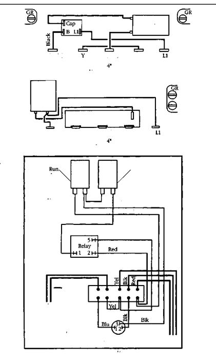
Single-phase control boxes
Checking and repairing procedures (Power on)
Caution: Power must be on for these tests. Do not touch any live parts.
A. General procedures:
1. Establish line power.
2. Check no load voltage (pump not running).
3. Check load voltage (pump running).
4. Check current (amps) in all motor leads.
B. Use of volt/amp meter:
1. Meter such as Amprobe Model RS300 or equivalent may be used.
2. Select scale for voltage or amps depending on tests.
3. When using amp scales, select highest scale to allow for inrush current, then select for midrange reading.
C. Voltage measurements:
Step 1, no load.
1. Measure voltage at LI and L2 of pressure switch or line contractor.
2. Voltage Reading: Should be ± 10% of motor rating.
Step 2, load.
1. Measure voltage at load side of pressure switch or line contractor with pump running.
2. Voltage Reading: Should remain the same except for slight dip on starting.
D. Current (amp) measurements:
1. Measure current on all motor leads. Use 5 conductor test cord for Q. D. control boxes.
2. Amp Reading: Current in Red lead should momentarily be high, then drop within one second. This verifies relay or solid state relay operation.
E. Voltage symptoms:
1. Excessive voltage drop on starting.
2. Causes: Loose connections, bad contacts or ground faults, or inadequate power supply.
F. Current symptoms:
1. Relay or switch failures will cause Red lead current to remain high and overload tripping.
2. Open run capacitor(s) will cause amps to be higher than normal in the Black and Yellow motor leads and lower than normal or zero amps in the Red motor lead.
3. Relay chatter is caused by low voltage or ground faults.
4. A bound pump will cause locked rotor amps and overloading tripping.
5. Low amps may be caused by pump running at shutoff, worn pump or stripped splines.
6. Failed start capacitor or open switch/relay are indicated if the red lead current is not momentarily high at starting.
|
|
|
Single-phase control boxes
Checking and repairing procedures (Power off)
Caution: Turn power off at the power supply panel and discharge capacitors before using ohmmeter.
A. General procedures:
1. Disconnect line power.
2. Inspect for damaged or burned parts, loose connections, etc.
3. Check against diagram in control box for misconnections.
4. Check motor insulation and winding resistance.
B. Use of ohmmeter:
1. Ohmmeter such as Simpson Model 372 or 260. Triplet Model 630 or 666 may be used.
2. Whenever scales are changed, clip ohmmeter lead together and “zero balance” meter.
C. Ground (insulation resistance) test:
1. Ohmmeter Setting: Highest scale R x 10K, or R x 100K
2. Terminal Connections: One ohmmeter lead to “Ground” terminal or Q. D. control box lid and touch other lead to the other terminals on the terminal hoard.
3. Ohmmeter Reading: Pointer should remain at infinity (°°).
Additional tests
Solid state capacitor run (CRC) control box
A. Run capacitor
1. Meter setting: R X 1,000
2. Connections: Red and Black leads
3. Correct meter reading: Pointer should swing toward zero, then drift back to infinity.
B. Inductance coil
1. Meter setting: R X 1
2. Connections: Orange leads
3. Correct meter reading: Less than 1 ohm.
C. Solid state switch
Step 1 triac test
1. Meter setting: R X 1,000
2. Connections: R(Start) terminal and Orange lead on start switch.
3. Correct meter reading: Should be near infinity after swing.
Step 2 coil test
1. Meter setting: R x 1
2. Connections: Y(Common) and L2.
3. Correct meter reading: Zero ohms
|
|
|
|
|
|
 |
|
|
|
|
|
|
|
|
|
|
|
|
|
|
|
|
|
|
В (main) Y (comm) R (start) L2
|
|
|
|
|
|
|
|
|
|
|
|
 |
|
|
|
|
 |
|
|
 |
 |
|
|
|
|
|
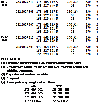
Integral horsepower control box parts
|
Motor
rating
|
Control box
|
|
Capacitors
|
|
|
|
hp dia.
|
(1) model no.
|
Part no. (2)
|
MFD
|
Volts
|
Qty.
|
|
5-6"
|
282 2009 202
|
275 468 117 S
|
130-154
|
330
|
2
|
|
|
275 479 103 (5)
|
15
|
370
|
2
|
|
282 2009 203
|
275 468 117 S
|
130-154
|
330
|
2
|
|
|
155 327 101 R
|
30
|
370
|
1
|
|
5-6"
|
282 2009 303
|
275 468 117 S
|
130-154
|
330
|
2
|
|
DLX
|
|
155 327 101 R
|
30
|
370
|
1
|
|
7V2-6"
|
282 2019 210
|
275 468 119 S
|
270-324
|
330
|
1
|
|
|
275 468 117 S
|
130-154
|
330
|
1
|
|
|
155 327 109 R
|
45
|
370
|
1
|
|
282 2019 202
|
275 468 117S
|
130-154
|
330
|
3
|
|
|
275 479 103 R (5)
|
15
|
370
|
3
|
|
282 2019 203
|
275 468 117 S
|
130-154
|
330
|
3
|
|
|
155 327 101 R
|
30
|
370
|
1
|
|
|
155 328 101 R
|
15
|
370
|
1
|
|
7У2-6"
|
282 2019 310
|
275 468 119 S
|
270-324
|
330
|
1
|
|
DLX
|
|
275 468 117 S
|
130-154
|
330
|
1
|
|
|
155 327 109 R
|
45
|
370
|
1
|
|
282 2019 303
|
275 468 117 S
|
130-154
|
330
|
3
|
|
|
155 327 101 R
|
30
|
370
|
1
|
|
|
155 328 101 R
|
15
|
370
|
1
|
|
10-6"
|
282 2029 210
|
275 468 119 S
|
270-324
|
330
|
2
|
|
|
155 327 102 R
|
35
|
370
|
2
|
|
282 2029 202
|
275 468 117 S
|
130-154
|
330
|
4
|
|
|
275 479 103 R (5)
|
15
|
370
|
5
|
|
282 2029 203
|
275 468 117 S
|
130-154
|
330
|
4
|
|
|
155 327 101 R
|
30
|
370
|
2
|
|
|
155 328 101 R
|
15
|
370
|
1
|
|
282 2029 207
|
275 468 119 S
|
270-324
|
330
|
2
|
|
|
155 327 101 R
|
30
|
370
|
2
|
|
|
155 328 101 R
|
15
|
370
|
1
|
|
 |
|
FIGURE 12.15 ■ (Continued) Data chart for single-phase motors. (Courtesy of McGraw-Hill)
|
|
|
Integral horsepower control box parts
|
|
|
hp dia.
|
model no.
|
Part no.
|
MFD
|
Volts
|
Qty.
|
|
ІУ2-4"
|
282 3008 110
|
275 464
|
113 S
|
105-126
|
220
|
1
|
|
|
155 328
|
102 R
|
10
|
370
|
1
|
|
282 3007 202 or
|
275 461
|
107 S
|
105-126
|
220
|
1
|
|
282 3007 102
|
275 479
|
102 R (5)
|
10
|
370
|
1
|
|
282 3007 203 or
|
275 461
|
107 S
|
105-126
|
220
|
1
|
|
282 3007 103
|
155 328
|
102 R
|
10
|
370
|
1
|
|
2-4"
|
282 3018 110
|
275 464
|
113 s
|
105-126
|
220
|
1
|
|
|
155 328
|
103 R
|
20
|
370
|
1
|
|
282 3018 202
|
275 464
|
113 S
|
105-126
|
220
|
1
|
|
|
275 479
|
105 R (5)
|
20
|
370
|
1
|
|
282 3018 203 or
|
275 464
|
113 S
|
105-126
|
220
|
1
|
|
282 3018 103
|
155 328
|
103 R
|
20
|
370
|
1
|
|
2-4"
|
282 3018 310
|
275 464
|
113 s
|
105-126
|
220
|
1
|
|
DLX
|
|
155 328
|
103 R
|
20
|
370
|
1
|
|
282 3019 103
|
275 464
|
113 S
|
105-126
|
220
|
1
|
|
|
155 328
|
103 R
|
20
|
370
|
1
|
|
3-М"
|
282 3028 110
|
275 463
|
111 s
|
208-250
|
220
|
1
|
|
|
155 327
|
102 R
|
35
|
370
|
1
|
|
282 3028 202
|
275 463
|
111 S
|
208-250
|
220
|
1
|
|
|
275 481
|
102 R (5)
|
35
|
370
|
2
|
|
282 3028 203 or
|
275 463
|
111 S
|
208-250
|
220
|
1
|
|
282 3028 103
|
155 327
|
102 R
|
35
|
370
|
1
|
|
3-4’
|
282 3028 310
|
275 463
|
111 S
|
208-250
|
220
|
1
|
|
DLX
|
|
155 327
|
102 R
|
35
|
370
|
1
|
|
282 3029 103
|
275 463
|
111 S
|
208-250
|
220
|
1
|
|
|
155 327
|
102 R
|
35
|
370
|
1
|
|
5-4"
|
282 1138 110
|
275 468
|
118 S
|
216-259
|
330
|
1
|
|
& 6"
|
|
155 327
|
101 R
|
30
|
370
|
2
|
|
5-4"
|
282 1139 202
|
275 468
|
118 S
|
216-259
|
330
|
1
|
|
|
275 479
|
103 R (5)
|
15
|
370
|
4
|
|
282 1139 203 or
|
275 468
|
118 S
|
216-259
|
330
|
1
|
|
282 1139 003
|
155 327
|
101 R
|
30
|
370
|
2
|
|
5-4"
|
282 1138 310 or
|
275 468
|
118 S
|
216-259
|
330
|
1
|
|
& 6"
|
282 1139 310
|
155 327
|
101 R
|
30
|
370
|
2
|
|
DLX
|
|
|
|
|
|
|
|
5-4"
|
282 1139 303 or
|
275 468
|
118 S
|
216-259
|
330
|
1
|
|
DLX
|
282 1139 103
|
155 327
|
101 R
|
30
|
370
|
2
|
|
Motor
rating Control box (1) Capacitors
|
|
FOOTNOTES:
(1) Lightning arrestor 150 814 902 suitable for all control boxes
(2) S = Start M = Main L = Line R = Run DXL = Deluxe control box with line contactor.
|


FIGURE 12.16 ■ Data chart for single-phase motors. (Courtesy of McGraw-Hill)
|
QD control box parts
|
Hp
|
Volts
|
Control box model no.
|
(1) Solid state SW or QD (blue) relay
|
Start
capacitor
|
MFD
|
|
Уз
|
115
|
2801024910
2801024915
|
152138905(5)
223415905(5)
|
275464125
275464125
|
159-191
159-191
|
|
Уз
|
230
|
2801034910
2801034915
|
152138901(5)
223415901(5)
|
275464126
275464126
|
43-53
43-53
|
|
Уг
|
115
|
2801044910
2801044915
|
152138906(5)
223415906(5)
|
275464201
275464201
|
250-300
250-300
|
|
Уз
|
230
|
2801054910
2801054915
|
152138902(5)
223415902(5)
|
275464105
275464105
|
59-71
59-71
|
|
Уз
|
230
|
2824055010
2824055015
|
152138912
223415912(6)
|
275470115
275464105
|
43-52
59-71
|
|
Зл
|
230
|
2801074910
2801074915
|
152138903(5)
223415903(5)
|
275464118
275464118
|
86-103
86-103
|
|
3/4
|
230
|
2824075010
2824075015
|
152138913
223415913(6)
|
275470114
275470114
|
108-130
86-103
|
|
1
|
230
|
2801084910
2801084915
|
152138904(5)
223415904(5)
|
275464113
275464113
|
105-126
105-126
|
|
1
|
230
|
2824085010
2824085015
|
152138914
223415914(6)
|
275470114
275470114
|
108-130
108-130
|
|
FOOTNOTES:
|
|
|
|
|
|
|
(1) Prefixes 152 are solid state switches. Prefixes 223 are QD (Blue) Relays.
(2) Control boxes supplied with solid state relays are designed to operate on normal 230 V systems. For 208 V systems or where line voltage is between 200 V use the next larger cable size, or use boost transformer to raise the voltage to 230 V.
(3) Voltage relay kits 115 V, 305 102 901 and 230 V. 305 102 902 will replace either current voltage or QD Relays, and solid state switches.
(4) QD control boxes produced H85 or later do not contain an overload in the capacitor. On winding thermal overloads were added to three-wire motors rated Vi-1 hp in A85. If a control box dated H85 or later is applied with a motor dated M84 or earlier, overload protection can be provided by adding an overload kit to the control box.
(5) May be replaced with QD relay kits 305 101 901 thru 906. Use same kit suffix as switch or relay suffix.
(6) Replace with CRC QD Relaying Kits, 223 415 912 with 305 105 901, 223 415 913 with 305 105 902 and 223 415 914 with 305 105 903.
|
|
|
|
|
Symptoms Probable cause
Won’t start No electrical power
Wrong voltage Bad pressure switch Bad electrical connection Bad motor
Motor contacts are open Motor shaft is seized
Runs, but produces no water Needs to be primed
Foot valve is above the water level in the well
Strainer clogged Suction leak
Starts and stops too often Leak in the piping
Bad pressure switch Bad air control valve Waterlogged pressure tank Leak in pressure tank
Low water pressure in pressure tank Strainer on foot valve is partially
blocked
Leak in piping
Bad air charger
Worn impeller hub
Lift demand is too much for the
pump
Pump does not cut off when working Pressure switch is bad
pressure is obtained Pressure switch needs adjusting
Blockage in the piping
|
|
|
|
|
Symptoms Probable cause
Won’t start No electrical power
Wrong voltage Bad pressure switch Bad electrical connection
Starts, but shuts off fast Circuit breaker or fuse is inadequate
Wrong voltage
Bad control box
Bad electrical connections
Bad pressure switch
Pipe blockage
Pump is seized
Control box is too hot
Runs, but does not produce water, or Check valve stuck in closed position
produces only a small quantity Check valve installed backward
Bad electrical wiring Wrong voltage
Pump is sitting above the water in the well
Leak in the piping Bad pump or motor Broken pump shaft Clogged strainer Jammed impeller
Low water pressure in pressure tank Pressure switch needs adjusting
Bad pump Leak in piping Wrong voltage
Pump runs too often Check valve stuck open
Pressure tank is waterlogged and needs air ipjected Pressure switch needs adjusting Leak in piping Wrong-size pressure tank
|
|
|
|
|
Symptoms
Relief valve leaks slowly Relief valve blows off periodically
No hot water
Water not hot enough
Water too hot Water leaks from tank
|
|
|
Probable cause
Bad relief valve
High water temperature High pressure in tank Bad relief valve
Electrical power is off Elements are bad Defective thermostat Inlet valve is closed
An element is bad Bad thermostat Thermostat needs adjusting
Thermostat needs adjusting Controls are defective
Hole in tank
Rusted-out fitting in tank
|
|
|
|
|
Symptoms
Relief valve leaks slowly Relief valve blows off periodically
No hot water
Water not hot enough Water too hot
Water leaks from tank
|
|
|
Probable cause
Bad relief valve
High water temperature High pressure in tank Bad relief valve
Out of gas Pilot light is out Bad thermostat Control valve is off Gas valve closed
Bad thermostat Thermostat needs adjusting
Thermostat needs adjusting Controls are defective Burner will not shut off
Hole in tank
Rusted-out fitting in tank
|
|
|
|
|
Symptoms Probable cause
|
Wont’t drain
|
Clogged drain Clogged tub waste Clogged trap
|
|
Drains slowly
|
Hair in tub waste Partial drainage blockage
|
|
Won’t hold water
|
Tub waste needs adjusting
|
|
Won’t release water
|
Tub waste need adjusting
|
|
Gurgles as it drains
|
Partial drainage blockage Partial blockage in the vent
|
|
Water drips from spout
|
Bad faucet washers/cartridge Bad faucet seats
|
|
Water comes out spout and shower at the same time
|
Bad diverter washer Bad diverter seat Bad diverter
|
|
Faucet will not shut off
|
Bad washers or cartridge Bad faucet seats
|
|
Poor water pressure
|
Partially closed valve Not enough water pressure Blockage in the faucet Partially frozen pipe
|
|
No water
|
Closed valve Broken pipe Frozen pipe
|
|
|
Symptoms Will not flush
Flushes poorly
|
|
 |
|
Water droplets covering tank Tank fills slowly
|
|
|
Makes unusual noises when flushed Water runs constantly
|
|
|
Water seeps from base of toilet Water dripping from tank
No water comes into the tank
|
|
|
|

|
Symptoms Won’t drain
Drains slowly Gurgles as it drains Water drips from shower head Faucet will not shut off Poor water pressure
No water
|
|
|
Probable cause
Clogged drain Clogged strainer Clogged trap
Hair in strainer Partial drainage blockage
Partial drainage blockage Partial blockage in the vent
Bad faucet washers/cartridge Bad faucet seats
Bad washers or cartridge Bad faucet seats
Partially closed valve Not enough water pressure Blockage in the faucet Partially frozen pipe
Closed valve Broken pipe Frozen pipe
|
|
|
|
|
Symptoms
Faucet drips from spout
Faucet leaks at base of spout Faucet will not shut off
Poor water pressure
No water
Drains slowly
Will not drain Gurgles as it drains Won’t hold water
|
|
|
Probable cause
Bad washers or cartridge Bad faucet seats
Bad О ring
Bad washers or cartridge Bad faucet seats
Partially closed valve Clogged aerator Not enough water pressure Blockage in the faucet Partially frozen pipe
Closed valve Broken pipe Frozen pipe
Hair on pop-up assembly Partial obstruction in drain or trap Pop-up needs to be adjusted
Blocked drain or trap Pop-up is defective
Partial drainage blockage Partial blockage in the vent
Pop-up needs adjusting Bad putty seal on drain
|
|
|
Symptoms Faucet drips from spout
Faucet leaks at base of spout Faucet will not shut off
Poor water pressure
|
|
|
|
Bad washers or cartridge Bad faucet seats
|
|
 |
|
No water
Drains slowly Will not drain Gurgles as it drains
Won’t hold water
|
|
|
|

|
Symptoms Faucet drips from spout
Faucet leaks at base of spout Faucet will not shut off
Poor water pressure
No water
Drains slowly Will not drain Gurgles as it drains
Won’t hold water
Spray attachment will not spray
Spray attachment will not cut off
|
|
|
|
Bad washers or cartridge Bad faucet seats
Bad О ring
Bad washers or cartridge Bad faucet seats
Partially closed valve Clogged aerator Not enough water pressure Blockage in the faucet Partially frozen pipe
Closed valve Broken pipe Frozen pipe
Partial obstruction in drain or trap
Blocked drain or trap
Partial drainage blockage Partial blockage in the vent
Bad basket strainer Bad putty seal on drain
Clogged holes in spray head Kinked spray hose
Bad spray head
|
|
 |
he plumbing code is complex. This chapter is not a replacement for the code, but it will give you a lot of pertinent information that you may use daily in a concise, accessible manner. The majority of the tables provided here were generously provided by the International Code Council, Inc. and the International Plumbing Code 2000. The visual nature of this chapter will allow you to answer many of your code questions by simply reviewing the numerous tables.
In most cases, the tables will speak for themselves. When there may be some confusion, I will provide some insight in the use of a table. For the most part, this is a reference chapter that will not require heavy reading. Consider this your fast track to code facts.
249
Copyright © 2005, 1999 by The McGraw-Hill Companies, Inc. Click here for terms of use.
APPROVED MATERIALS
|
WATER DISTRIBUTION PIPE
|
MATERIAL
|
STANDARD
|
|
Brass pipe
|
ASTM В 43
|
|
Chlorinated polyvinyl chloride (CPVC) plastic pipe and tubing
|
ASTM D 2846; ASTM F 441; ASTM F 442; CSA B137.6
|
|
Copper or copper-alloy pipe
|
ASTM В 42; ASTM В 302
|
|
Copper or copper-alloy tubing ("type K, WK, L, WL, M or WM)
|
ASTM В 75; ASTM В 88; ASTM В 251; ASTM В 447
|
|
Cross-linked polyethylene (PEX) plastic tubing
|
ASTM F 877; CSA CAN/CSA-B 137.5
|
|
Cross-linked polyethylene/
alumimim/cross-linked polyethylene (PEX-AL-PEX) pipe
|
ASTM F 1281; CSA CAN/CSA-B 137.10
|
|
Galvanized steel pipe
|
ASTM A 53
|
|
Polybutylene (PB) plastic pipe and tubing
|
ASTM D 3309; CSA CAN3-B137.8
|
|
FIGURE 13.1 ■ Approved materials for water distribution. (Courtesy of International Code Council, Inc. and the International Plumbing Code 2000)
|
WATER SERVICE PIPE
|
MATERIAL
|
STANDARD
|
|
Acrylonitrile butadiene styrene (ABS) plastic pipe
|
ASTM D 1527; ASTM D 2282
|
|
Asbestos-cement pipe
|
ASTM C 296
|
|
Brass pipe
|
ASTM В 43
|
|
Copper or copper-alloy pipe
|
ASTM В 42; ASTM В 302
|
|
Copper or copper-alloy tubing CIVpe K. WK, L, WL, M or WM)
|
ASTM В 75; ASTM В 88; ASTM В 251; ASTM В 447
|
|
Chlorinated polyvinyl chloride (CPVC) plastic pipe
|
ASTM D 2846; ASTM F 441; ASTM F 442; CSA В137.6
|
|
Ductile iron water pipe
|
AWWA Cl51; AWWA Cl 15
|
|
Galvanized steel pipe
|
ASTM A 53
|
|
Polybutylene (PB) plastic pipe and tubing
|
ASTM D 2662; ASTM D 2666; ASTM D 3309; CSA BI37.8
|
|
Polyethylene (PE) plastic pipe
|
ASTM D 2239; CSA CAN/CSA-B 137.1
|
|
Polyethylene (PE) plastic tubing
|
ASTM D 2737; CSA В137.1
|
|
Cross-linked polyethylene (PEX) plastic tubing
|
ASTM F 876; ASTM F 877; CSA CAN/CSA-B137.5
|
|
Cross-linked polyethylene/ aluminum/cross-linked polyethylene (PEX-AL-PEX) pipe
|
ASTM F 1281; CSACAN/CSA B137.10
|
|
Polyethylene/aluminum/ polyethylene (PE-AL-PE) pipe
|
ASTM F 1282; CSA CAN/CSA-B 137.9
|
|
Polyvinyl chloride (PVC) plastic pipe
|
ASTM D 1785; ASTM D 2241; ASTM D 2672; CSA CAN/CSA-B137.3
|
|
FIGURE 13.2 ■ Approved materials for water service piping. (Courtesy of International Code Council, Inc. and the International Plumbing Code 2000)
|
BUILD! NO SEWER PIPE
|
MATERIAL
|
STANDARD
|
|
Acrylonitrile butadiene styrene (ABS) plastic pipe
|
ASTM D 2661; ASTM D 2751; ASTMF628
|
|
Asbestos-cement pipe
|
ASTM C 428
|
|
Cast-iron pipe
|
ASTM A 74; ASTM A 888; CISPI 301
|
|
Coextruded composite ABS DWV sch 40 IPS pipe (solid)
|
ASTM F 1488
|
|
Coextruded composite ABS DWV sch 40 IPS pipe (cellular core)
|
ASTM F 1488
|
|
Coextruded composite PVC DWV sch 40 IPS pipe (solid)
|
ASTM F 1488
|
|
Coextruded composite PVC DWV sch 40 IPS pipe (cellular core)
|
ASTM F 1488
|
|
Coextruded composite PVC IPS DR – PS DWV. PS 140, PS 200
|
ASTM F 1488
|
|
Coextruded composite ABS sewer and drain DR – PS in PS35, PS50, PS100, PS140, PS200
|
ASTM F 1488
|
|
Coextruded composite PVC sewer and rain DR – PS in PS35, PS50, PS100, PS140. PS 200
|
ASTM F 1488
|
|
Concrete pipe
|
ASTM C 14; ASTM C 76; CSA A257.1; CSA CAN/CSA A257.2
|
|
Copper or copper-alloy tubing (ТУре К or L)
|
ASTM В 75; ASTM В 88; ASTM В 251
|
|
Polyvinyl chloride (PVC) plastic pipe (Type DWV, SDR26, SDR35, SDR41, PS50orPS100)
|
ASTM D 2665; ASTM D 2949; ASTM D 3034; ASTM F 891; CSA В 182.2; CSA CAN/CSA-B 182.4
|
|
Stainless steel drainage systems, Type 316L
|
ASME/ANSI A112.3.I
|
|
Vitrified clay pipe
|
ASTM C 4; ASTM C 700
|
|
FIGURE 13.3 ■ Approved materials for building sewer piping. (Courtesy of international Code Council, inc. and the international Plumbing Code 2000)
|
UNDERGROUND BUILDING DRAINAGE AND VENT PIPE
|
MATERIAL
|
STANDARD
|
|
Acrylonitrile butadiene styrene (ABS) plastic pipe
|
ASTM D 2661; ASTMF 628; CSAB181.1
|
|
Asbestos-cement pipe
|
ASTM C 428
|
|
Cast-iron pipe
|
ASTM A 74; CISPI 301; ASTM A 888
|
|
Coextmded composite ABS DWV sch 40 IPS pipe (solid)
|
ASTM F 1488
|
|
Coextruded composite ABS DWV sch 40 IPS pipe (cellular core)
|
ASTM F 1488
|
|
Coextruded composite PVC DWV sch 40 IPS pipe (solid)
|
ASTM F 1488
|
|
Coextruded composite PVC DWV sch 40 IPS pipe (cellular core)
|
ASTM F 1488
|
|
Coextruded composite PVC IPS – DR, PS 140, PS200 DWV
|
ASTM F 1488
|
|
Copper or copper alloy tubing (Type K, L, M or DWV)
|
ASTM В 75; ASTM В 88; ASTM В 251; ASTM В 306
|
|
Polyolefin pipe
|
CS A CAN/CSA-B 181.2
|
|
Polyvinyl chloride (PVC) plastic pipe (Type DWV)
|
ASTM D 2665; ASTM D 2949; ASTMF 891; CSA CAN/CSA-B 181.2
|
|
Stainless steel drainage systems. Type 316L
|
ASME/ANSI A112.3.I
|
|
FIGURE 13.4 ■ Approved materials for underground building drainage and vent pipe. (Courtesy of International Code Council, Inc. and the International Plumbing Code 2000)
|
PIPE FITTINGS
|
MATERIAL
|
STANDARD
|
|
Acrylonitrile butadiene styrene (ABS) plastic
|
ASTM D 3311; CSA B181.1; ASTM D 2661
|
|
Cast iron
|
ASME В 16.4; ASME В16.12; ASTM A 74; ASTM A 888; CISPI 301
|
|
Coextruded composite ABS DWV sch 40 IPS pipe (solid or cellular core)
|
ASTM D 2661; ASTM D 3311; ASTM F 628
|
|
Coextruded composite PVC DWV sch 40 pipe IPS-DR, PS 140, PS200 (solid or cellular core)
|
ASTM D 2665; ASTM D 3311; ASTM F 891
|
|
Coextruded composite ABS sewer and drain DR-PS in PS35, PS50, PS 100, PS 140, PS 200
|
ASTM D 2751
|
|
Coextruded composite PVC sewer and drain DR-PS in PS35, PS50, PS100, PS140, PS200
|
ASTM D 3034
|
|
Copper or copper alloy
|
ASME В16.15; ASME B16.18; ASME В 16.22; ASME В 16.23; ASME В 16.26; ASME В 16.29; ASME В 16.32
|
|
Glass
|
ASTM C 1053
|
|
Gray iron and ductile iron
|
AWWAC110
|
|
Malleable iron
|
ASME В 16.3
|
|
Polyvinyl chloride (PVC) plastic
|
ASTM D 3311; ASTM D 2665
|
|
Stainless steel drainage systems, Types 304 and 316L
|
ASME/ANSIA112.3.1
|
|
Steel
|
ASME В 16.9; ASMEB16.il; ASME В 16.28
|
|
FIGURE 13.5 ■ Approved materials for aboveground drainage and vent pipe. (Courtesy of International Code Council, Inc. and the International Plumbing Code 2000)
|
ABOVE-GROUND DRAINAGE AND VENT PIPE
|
MATERIAL
|
STANDARD
|
|
Acrylonitrile butadiene styrene (ABS) plastic pipe
|
as™ D 2661; as™ F 628; CSAB181.1
|
|
Brass pipe
|
AS™ В 43
|
|
Cast-iron pipe
|
AS™ A74;CISP! 301; AS™ A 888
|
|
Coexiruded composite ABS DWV sch 40 IPS pipe (solid)
|
ASTM F 1488
|
|
Coextroded composite ABS DWV sch 40 IPS pipe (cellular core)
|
AS™ F 1488
|
|
Coextruded composite PVC DWV sch 40 IPS pipe (solid)
|
AS™ F 1488
|
|
Coextruded composite PVC DWV sch 40 IPS pipe (cellular core)
|
ASTM F 1488
|
|
Coextruded composite PVC IPS – DR, PS 140, PS200 DWV
|
AS™ F 1488
|
|
Copper or copper-alloy pipe
|
AS™ В 42; AS™ В 302
|
|
Copper or copper-alloy tubing OVpe K, L, M or DWV)
|
ASTM В 75; ASTM В 88; AS™ В 251; AS™ В 306
|
|
Galvanized steel pipe
|
ASTM A 53
|
|
Glass pipe
|
AS™ C 1053
|
|
Polyolefin pipe
|
CSA CAN/CSA-B181.2
|
|
Polyvinyl chloride (PVC) plastic pipe (Type DWV)
|
AS™ D 2665; AS™ D 2949; AS™ F 891; CSA CAN/CSA-B 181.2; ASTO F 1488
|
|
Stainless steel drainage systems, types 304 and 316L
|
ASME/ANS1 A112.3.1
|
|
FIGURE 13.6 ■ Approved materials for pipe fittings. (Courtesy of international Code Council, inc. and the international Plumbing Code 2000)
|
SIZE OF PIPE IDENTIFICATION
|
PIPE DIAMETER (InchM)
|
LENGTH OF
BACKGROUND COLOR FIELD (InchM)
|
SIZE OF LETTERS (InchM)
|
|
V4 to 1V4
|
8
|
0.5
|
|
l‘/2to2
|
8
|
0.75
|
|
2!/2to6
|
12
|
1.25
|
|
8 to 10
|
24
|
2.5
|
|
over 10
|
32
|
3.5
|
For SI: 1 inch = 25.4 ram.
|
FIGURE 13.7 ■ Requirements of pipe identification. (Courtesy of International Code Council, inc. and the international Plumbing Code 2000)
MINIMUM PLUMBING FACILITIES
|
Ml MM UN ПЛАМЕН OF FLUhHWIQ FACtUTIEB"
|
watwclomt* IllHnd* aaa ■colon 41M)
|
LAYftTONE*
|
MINIUM/
■HOWCM
|
FOUMTAMB
IMtbdhn
410.1)
|
ото»
|
|
OCCUPANCT
|
■Me
|
Nmuri
|
|
A
S
S
E
M
В
L
Y
|
NlghKlubs
|
l pet 40
|
1 per 40
|
1 per 75
|
—
|
1 per 500
|
1 service sink
|
|
ResUwnrats
|
1 per 75
|
1 per 73
|
і per 200
|
—
|
1 pe 500
|
] service sink
|
|
Theaters, halls, museuml, etc.
|
1 per 125
|
1 per AS
|
l per 300
|
—
|
1 per 500
|
1 service sink
|
|
Coliseums, arena* (leu than 3,000 seats)
|
1 per 75
|
1 per 40
|
t per ISO
|
–
|
t per 1.000
|
1 service sink
|
|
Coliseums, вела (3.000 seats or greater)
|
1 pea 120
|
I per 60
|
Male 1 per 200 Female 1 per 150
|
|
1 pe 1,000
|
1 service rink
|
|
Churches6
|
1 per ISO
|
3 per 7S
|
1 per 200
|
—
|
I per 1,000
|
1 service sink
|
|
Stadiums (lew than 3.000 seats), pools, etc.
|
l per 100
|
1 per 50
|
1 per 150
|
–
|
1 per 1,000
|
1 service sink
|
|
Stadium* (3,000 seat* or greater)
|
1 per ISO
|
1 pe 75
|
Male 1 per 200 Female 1 pet 150
|
|
І per I.000
|
3 service sink
|
|
Buineu (»e Sections 403.2, 403,4 and 403,5)
|
1 per 50
|
1 per R0
|
–
|
1 per 100
|
1 service link
|
|
Educational
|
1 per 50
|
1 p«50
|
—
|
і pet ibo
|
1 service sink
|
|
Factory and іпАютіїї
|
! per 100
|
1 per 100
|
fsee Section 411)
|
1 per 400
|
1 ктсе rink
|
|
Passenger terminals and transportation facilities
|
l per 500
|
1 per 750
|
–
|
1 per 1,000
|
1 service sink
|
|
1
N
S
T
1
T
и
T
f
о
N
A
L
|
Residential care
|
1 per 10
|
1 per 10
|
1 per 8
|
1 per 100
|
1 service sink
|
|
Hospitals, ambulatory nursing home pillcnls1′
|
1 pci room*1
|
1 per loom11
|
1 per 15
|
і per 100
|
1 service нпк per floor
|
|
Day nurseries, sanitariums, nonamhulatwy nursing home patients, eic. c
|
1 per 15
|
1 per 15
|
l per 15е
|
3 per IOC
|
3 service sink
|
|
Employees, wher lhan residential ci
|
1 per 25
|
1 per 35
|
–
|
1 per 100
|
–
|
|
Viiiiots. other than residential care
|
1 per 75
|
1 per 100
|
–
|
1 per 300
|
–
|
|
Pnremri
|
I per cell
|
1 per cell
|
1 per 15
|
1 pci 10O
|
1 service sink
|
|
Asylums, refnrmamries, etc. e
|
1 per IS
|
1 per IS
|
1 per IS
|
1 per 100
|
1 service sink
|
|
Mercantile (see Sections 403.2, 403.4 and 403.5)
|
1 per 500
|
1 per 750
|
–
|
1 per 1.000
|
1 service sink
|
|
R
E
5
1
D
Б
N
T
E
A
L
|
Hotels, motels
|
1 per guestroom
|
1 per
guestroom
|
t per guestroom
|
–
|
1 service sink
|
|
Lodges
|
1 per 10
|
1 per 10
|
] per 8
|
1 per 100
|
] service sink
|
|
Multiple family
|
1 per dwelling anil
|
l per
dwelling unit
|
1 per dwelling unit
|
–
|
1 kitchen rink per dwelling unit:
1 automatic clothes washer connection per 20 dwelLing tin Us
|
|
Dormitories
|
1 per 10
|
1 per! Q
|
1 per В
|
1 per 100
|
1 service sink
|
|
One- and two-family dwellings
|
I per dwelling unit
|
l per
dwelling unit
|
1 per dwelling unit
|
–
|
1 kitchen sink per dwelling unit,
1 automatic clottjc*
washer connection per dwelling unit*
|
|
Storage (see Sections403,2 and 403.4)
|
1 per 100
|
1 per 100
|
(see Section 411)
|
1 per 1,000
|
l service sink
|
■- The fin turn shown srt based oaonr fixture being the mi rmnumrcqvircd for the number of persons indrcaiod oraiyfndiM of the number of penons ladicatcd TV number of oceupvm A ill be determined by ihc hft*rnanvnal Building Codt. b. Piutrci located In adjacent ojllduifj нМег the ownership « control of (he church dull be made available duria| period! the choreb is occupied C. Toilet facilities for employed shall be separate from fur [litres for ntmatei or paneaii.
d, Л пгціе-оссирапі toilet room with me water daact and one lavatory «еггіп| тхч топе than (wo adjacent patient room* thill be permitted where well irom <» provided with direct access from each patient room and with frovisiont for privacy.
e. For day nurseries, i maximum of one ЬпЫцЬ shall be required
f For irtaebed one – and two-farm I у dweltavgx, one automatic clothes wadier connection shall be required per 20 dwelling urns.
|
FIGURE 13.9 ■ Minimum plumbing facilities. (Courtesy of International Code Council, Inc. and the International Plumbing Code 2000)
|
MINIMUM SIZES OF FIXTURE WATER SUPPLY PIPES
|
FIXTURE
|
MINIMUM PIPE SIZE (inch)
|
|
Bathtubs (60" x 32" and smaller)®
|
v2
|
|
Bathtubs (larger than 60" x 32")
|
V2
|
|
Bidet
|
3/8
|
|
Combination sink and tray
|
v2
|
|
Dishwasher, domestic®
|
v2
|
|
Drinking fountain
|
%
|
|
Hose bibbs
|
‘/2
|
|
Kitchen sink®
|
V2
|
|
Laundry, 1, 2 or 3 compartments®
|
‘/2
|
|
Lavatory
|
3/8
|
|
Shower, single head®
|
‘/2
|
|
Sinks, flushing rim
|
3/4
|
|
Sinks, service
|
v2
|
|
Urinal, flush tank
|
lh
|
|
Urinal, flush valve
|
3/4
|
|
Wall hydrant
|
v2
|
|
Water closet, flush tank
|
3/8
|
|
Water closet, flush valve
|
1
|
|
Water closet, flushometer tank
|
3/8
|
|
Water closet, one piece®
|
V2
|
For SI: 1 inch = 25.4 шш, 1 foot = 304.8 mm, 1 psi = 6.895 kPa.
a. Where the developed length of the distribution line is 60 feet or less, and the available pressure at the meter is a minimum of 35 psi, the minimum size of an individual distribution line supplied from a manifold and installed as part of a parallel water distribution system shall be one nominal tube size smaller than the sizes indicated.
|
FIGURE 13.10 ■ Minimum number of plumbing facilities. (Courtesy of International Code Council, Inc. and the International Plumbing Code 2000)
FIXTURE SUPPLIES
MAXIMUM FLOW RATES AND CONSUMPTION
FOR PLUMBING FIXTURES AND FIXTURE FITTINGS
|
PLUMBING FIXTURE OR FIXTURE FITTING
|
MAXIMUM FLOW RATE OR QUANTITY*
|
|
Water closet
|
1.6 gallons per flushing cycle
|
|
Urinal
|
1.0 gallon per flushing cycle
|
|
Shower head®
|
2.5 gpm at 60 psi
|
|
Lavatory, private
|
2.2 gpm at 60 psi
|
|
Lavatory (other than metering), public
|
0.5 gpm at 60 psi
|
|
Lavatory, public (metering)
|
0.25 gallon per metering cycle
|
|
Sink faucet
|
2.2 gpm at 60 psi
|
|
For SI: I gallon = 3.785 L, 1 gallon per minute = 3.785 L/m, 1 psi = 6.895 kPa.
a. A hand-held shower spray is a shower head.
b. Consumption tolerances shall be determined from referenced standards.
|
FIGURE 13.11 ■ Maximum flow rates and consumption for plumbing fixtures and fixture fittings. (Courtesy of International Code Council, Inc. and the International Plumbing Code 2000)
|
MANIFOLD SIZING
|
NOMINAL SIZE INTERNAL DIAMETER (Inch*»)
|
MAXIMUM DEMAND (gpm)
|
|
Velocity M 4 foot рагмсомі
|
Velocity at S fact p*ra*cand
|
|
‘/2
|
2
|
5
|
|
J/4
|
6
|
11
|
|
1
|
10
|
20
|
|
l‘/4
|
15
|
31
|
|
iV2
|
22
|
44
|
For SI: 1 inch = 25.4mm, 1 gallon per minute = 3.785 L/m, 1 foot per second
= 0 305 mis.
|
FIGURE 13.12 ■ Maximum flow rates and consumption for plumbing fixtures and fixture fittings. (Courtesy of International Code Council, Inc. and the International Plumbing Code 2000)
WATER DISTRIBUTION SYSTEM DESIGN CRITERIA
REQUIRED CAPACmES AT FIXTURE SUPPLY PIPE OUTLETS
|
FIXTURE SUPPLY OUTLET SERVING
|
FLOW RATE* (gpm)
|
FLOW
PRESSURE
(P*l)
|
|
Bathtub
|
4
|
8
|
|
Bidet
|
2
|
4
|
|
Combination fixture
|
4
|
8
|
|
Dishwasher, residential
|
2.75
|
8
|
|
Drinking fountain
|
0.75
|
8
|
|
Laundry tray
|
4
|
8
|
|
Lavatory
|
2
|
8
|
|
Shower
|
3
|
8
|
|
Shower, temperature controlled
|
3
|
20
|
|
Sillcock, hose bibb
|
5
|
8
|
|
Sink, residential
|
2.5
|
8
|
|
Sink, service
|
3
|
8
|
|
Urinal, valve
|
15
|
15
|
|
Water closet, blow out, flushometer valve
|
35
|
25
|
|
Water closet, flushometer tank
|
1.6
|
15
|
|
Water closet, siphonic, flushometer valve
|
25
|
15
|
|
Water closet, tank, close coupled
|
3
|
8
|
|
Water closet, tank, one piece
|
6
|
20
|
|
For SI: 1 psi = 6.895 кРа, I gallon per minute (gpm) = 3.785 L/m.
a. For additional requirements for flow rates and quantities, see Section 604.4.
|
FIGURE 13.13 ■ Water distribution system design criteria required capacities at fixture supply pipe outlets. (Courtesy of International Code Council, Inc. and the International Plumbing Code 2000)
HORIZONTAL FIXTURE BRANCHES AND STACKS*
|
DIAMETER OF PIPE (inch**)
|
MAXIMUM NUMBER OF DRAINAGE FIXTURE UNITS (dfu)
|
|
Total for a horizontal branch
|
Slackib
|
|
Total discharge Into ona branch interval
|
Total for stack of thr** branch interval* or lata
|
Total for stack greater than thr** branch interval*
|
|
l‘/2
|
3
|
2
|
4
|
8
|
|
2
|
6
|
6
|
10
|
24
|
|
2‘/2
|
12
|
9
|
20
|
42
|
|
3
|
20
|
20
|
48
|
72
|
|
4
|
160
|
90
|
240
|
500
|
|
5
|
360
|
200
|
540
|
1,100
|
|
6
|
620
|
350
|
960
|
1,900
|
|
8
|
1.400
|
600
|
2,200
|
3,600
|
|
10
|
2,500
|
1.000
|
3,800
|
5,600
|
|
12
|
2.900
|
1,500
|
6,000
|
8,400
|
|
15
|
7,000
|
Footnote c
|
Footnote c
|
Footnote c
|
|
For SI; I inch = 25.4 mm.
|
a. Docs not include branches of the building drain. Refer to Table 710.1(1).
b. Slacks shall be sized based on the total accumulated connected load at each story or branch interval. As the total accumulated connected load decreases, stacks are permitted to be reduced in size. Stack diameters shall not be reduced to less than one-half of the diameter of the largest stack size required.
c.  Sizing load based on design criteria.
|
DIAMETER OF PIPE (inches)
|
MAXIMUM NUMBER OF DRAINAGE FIXTURE UNITS CONNECTED TO ANY PORTION OF THE BUILDING DRAIN OR THE BUILDING SEWER, INCLUDING BRANCHES OF THE BUILDING DRAIN*
|
|
Slope per foot
|
|
Inch
|
Vs Inch
|
V* Inch
|
V2Inch
|
|
i’/4
|
—
|
—
|
і
|
1
|
|
i’/2
|
—
|
—
|
3
|
3
|
|
2
|
—
|
—
|
21
|
26
|
|
2’/2
|
—
|
—
|
24
|
31
|
|
3
|
—
|
36
|
42
|
50
|
|
4
|
—
|
180
|
216
|
250
|
|
5
|
—
|
390
|
480
|
575
|
|
6
|
—
|
700
|
840
|
1,000
|
|
8
|
1,400
|
1,600
|
1,920
|
2,300
|
|
Ю
|
2,500
|
2,900
|
3,500
|
4.200
|
|
12
|
3,900
|
4,600
|
5,600
|
6,700
|
|
15
|
7,000
|
8,300
|
10,000
|
12,000
|
|
BUILDING DRAINS AND SEWERS
|
|
For SI: 1 inch = 25.4 mm, 1 inch per foot = 0.0833 mm/m.
a. The minimum size of any building drain serving a water closet shall be 3 inches.
|
FIGURE 13.15 ■ Drainage fixture units allowed for building drains and sewers. (Courtesy of International Code Council, Inc. and the International Plumbing Code 2000)
Maximum Unit Loading and Maximum Length of Drainage and Vent Piping
|
Six» of Pipe, Inches
(mm)
|
1-1/4
(32)
|
1-1/2
(40)
|
2
(50)
|
2-1/2
(65)
|
3
(80)
|
4
(100)
|
5
025)
|
6
(150)
|
8
(200)
|
10
(250)
|
12
(300)
|
|
Maximum Units
Drainage Piping1 Vertical Horizontal
|
1
1
|
22
1
|
163
83
|
323
143
|
48*
354
|
256 2165
|
600
428®
|
1380
7205
|
3600
2640s
|
5600
4680s
|
8400
8200s
|
|
Maximum Length
Drainage Piping Vertical, feet (m)
Horizontal (Unlimited)
|
45
(14)
|
65
(20)
|
85
(26)
|
146
(45)
|
212
(65)
|
300
(91)
|
390
(119)
|
510
(155)
|
750
(228)
|
|
|
Vent Piping (See note) Horizontal and Vertical Maximum Units Maximum Lengths, feet
____________________ !"2L-
|
1
45
.OIL
|
83
60
JUL
|
24
120
J3TL
|
48
180
J552_
|
84
212
ea
|
256
300
(91)
|
600
390
(119?
|
1380
510
(155)
|
3600
750
(228)
|
1 Excluding trap arm.
2 Except smks. urinals and dishwashers.
3 Except six-unit traps or water closets
4 Only four (4) water doseta or six-unit traps allowed on any vertical pipe or stack; and not to exceed three (3) water closets or six-unit traps on any horizontal branch or drain
5 Based on one-fourth (1/4) inch per tool (20.9 mm/m) slope. For one-eighth (t/8) inch per foot (10 4 mm/m) slope, multiply horizontal fixture units by a factor ol 0.8.
Not»: The diameter of an individual vent shall not be less than one and one-fourth (1-1/4) inches (31.8 mm) nor less than One-half (t/2> the diameter ot the drain to which it is connected. Fixture unit load values tor drainage and vent piping shall be computed from Tables 7-3 and 7^4. Not to exceed one-third (1/3) ol the total permitted length ol any vent may be Installed in a horizontal positron. When vents are increased one (1) pipe size for their entire length, the maximum length limitations specified in this table do not apply.
 FIGURE 13.16 ■ Maximum unit loading and maximum length of drainage and vent piping. (Courtesy of International Code Council, Inc. and the International Plumbing Code 2000)
|
SIZE OF COMBINATION DRAIN AND VENT PIPE
|
DIAMETER PIPE (Inchee)
|
MAXIMUM NUMBER OF DRAINAGE FIXTURE UNITS (dfu)
|
|
Connecting to ■ horizontal branch or alack
|
Connecting to a building drain or building eubdraln
|
|
2
|
3
|
4
|
|
2 lh
|
6
|
26
|
|
3
|
12
|
31
|
|
4
|
20
|
50
|
|
5
|
160
|
250
|
|
6
|
360
|
575
|
For SI: 1 inch = 25.4 mm.
|
FIGURE 13.17 ■ Size of combination drain and vent pipe. [Courtesy of International Code Council, Inc. and the International Plumbing Code 2000)
|
SLOPE OF HORIZONTAL DRAINAGE PIPE
|
SIZE (inches)
|
MINIMUM SLOPE (Inch per foot)
|
|
2V2 or less
|
‘/4
|
|
3 to 6
|
‘/8
|
|
8 or larger
|
‘/16
|
For SI: 1 inch = 25.4 шш, 1 inch per foot = 0.0833 mm/rn.
|
FIGURE 13.18 ■ Slope of horizontal drainage pipe. [Courtesy of International Code Council, Inc. and the International Plumbing Code 2000)
|
DRAINAGE FIXTURE UNITS FOR FIXTURE DRAINS Oft TRAPS
|
FIXTURE ORAM OH TRAP SIZE (InchM)
|
DRAINAGE FIXTURE UNIT VALUE
|
|
P/4
|
1
|
|
P/2
|
2
|
|
2
|
3
|
|
2’/2
|
4
|
|
3
|
5
|
|
4
|
6
|
For SI t inch = 25.4 mm
|
FIGURE 13.19 ■ Drainage fixture units for fixture drains or traps. (Courtesy of International Code Council, Inc. and the International Plumbing Code 2000)
MINIMUM CAPACITY OF SEWAGE PUMP
OR SEWAGE EJECTOR
|
DIAMETER OF THE DISCHARGE PIPE (inchas)
|
CAPACITY OF PUMP OR EJECTOR (gpm)
|
|
2
|
21
|
|
2’/2
|
30
|
|
3
|
46
|
For SI: 1 inch = 25.4 mm, 1 gpm = 3.785 L/m,
FIGURE 13.20 ■ Minimum capacity of sewage pump or sewage ejector. (Courtesy of international Code Council, Inc. and the international Plumbing Code 2000)
|
DftAMAGe FIXTURE UNIT® FOR RXTVRW AW GROUP*
|
FBCTUIIi: TYPE
|
опАїНлав латиш имг value AS LOAD FACTORS
|
мним на or TRAP
Hw)
|
|
Automatic clothes washers, commercial*
|
3
|
2
|
|
Automatic clothes washers, residential
|
2
|
2
|
|
Baihroo m group as defined in Sect! on 202 (1.6 gpf waier closet)’
|
5
|
—
|
|
Bathroom group is defined in Section 202 (water closet flushing greater than 1.6 gpf/
|
6
|
—
|
|
Bathtub** < with or without overhead shower or whirlpool attachments)
|
2
|
l’/l
|
|
Bidet
|
1
|
|
|
Combination sink and tray
|
2
|
I’o
|
|
Derail lavatory
|
1
|
]!/*
|
|
Dental unit or cuspidor
|
1
|
]’/.
|
|
Dishwashing machine, c domestic
|
2
|
l^a
|
|
Drinking fountain
|
lb
|
TV4
|
|
Emergency floor drain
|
0
|
2
|
|
Floor drains
|
2
|
2
|
|
Kitchen sink, domestic
|
2
|
!'<=
|
|
Kitchen sink, domestic with food waste grinder and/or dishwasher
|
2
|
1^2
|
|
Laundry tray (1 or 2 comparmems)
|
2
|
l’/2
|
|
Lavatory
|
1
|
U4
|
|
Shower
|
2
|
■ —^
|
|
Sink
|
2
|
T/2
|
|
Urinal
|
4
|
Footnoted
|
|
Urinal, 1 gallon per flush or less
|
2*
|
Footnote d
|
|
Wash sink (circular or multiple) each set of faucets
|
2
|
l‘fj
|
|
Water closet, flushorrsctcT tank, public Or private
|
4r
|
Footnote d
|
|
Water closet, private (1,6 gpf)
|
3*
|
Footnoted
|
|
Water closet, privste (flushing greater than 1.6 gpf)
|
4C
|
Footnote d
|
|
Water closet. public (1 6 gpf)
|
4C
|
Footnote d
|
|
Water closet, public (flushing greater rhan 1.6 gpf)
|
6C
|
Footnoie d
|
|
For Sr 1 inch = 23 4 nun, I gallpfl = 3 L
1- For <npi larger than 3 inches, uk fibte 709.2.
b. Л showeihead over a bathtub nr’whirlpool bathtub attachments does not menace the drainage Пинге unit value
c. See Sectkxvs 709.2 through 709 4 for methods о Г competing unit value of futures not lilted in Table 709.1 or for rating of devices with intermittent flows.
d. Trap si» shall be eoMisrem with Che fiature wrtmiie-
e. For the риізяие of computing lotds on bu i Idmgdiai nr and sewers, water closets’ч urinal t shall not be rated it a low d™ tuge future unit unteKthe lower vaiue air con firmed by testing
I. For fi і turn added tc>« dwelling unit bsihroora group, add the DFU value of those addi oonii fi* lures to the bat broom group fi stmt count.
FIGURE 13.21 ■ Drainage fixture units. (Courtesy of international Code Council, inc. and the international Plumbing Code 2000)
|
MAXIMUM DISTANCE OF FIXTURE TRAP FROM VENT
|
SIZE OF TRAP (inches)
|
SIZE OF FIXTURE DRAIN (inches)
|
SLOPE (Inch per loot)
|
DISTANCE FROM TRAP (feet)
|
|
l’/4
|
l‘/4
|
%
|
3 ‘/2
|
|
l’/4
|
l‘/2
|
>/4
|
5
|
|
1 ‘h
|
1 ’/2
|
’/4
|
5
|
|
l’/2
|
2
|
‘/4
|
6
|
|
2
|
2
|
%
|
6
|
|
3
|
3
|
‘/8
|
10
|
|
4
|
4
|
‘/8
|
12
|
For SI: 1 inch = 25.4 mm, 1 foot = 304 8 mm, 1 inch per foot = 0.0833 mm/ш.
|
FIGURE 13.22 ■ Maximum distance of fixture trap from vent.(Courtesy of International Code Council, Inc. and the International Plumbing Code 2000)
|
COMMON VENT SIZES
|
PIPE SIZE (Inches)
|
MAXIMUM DISCHARGE FROM UPPER FIXTURE DRAIN (Ли)
|
|
И/2
|
1
|
|
2
|
4
|
|
2‘/2 to 3
|
6
|
For SI: 1 inch = 25.4 mm.
|
 |
|
SIZE AND LENGTH OF SUMP VENTS
|
DiSCHARGE CAPACITY OF PUMP
|
MAXIMUM DEVELOPED LENGTH OF VENT (feet)"
|
|
Diameter of vant (inch**)
|
|
________ (9P™)__________
|
1V4
|
|
2
|
¥Гг
|
3
|
4
|
|
10
|
No limitb
|
No limit
|
No limit
|
No limit
|
No limit
|
No limit
|
|
20
|
270
|
No limit
|
No limit
|
No limit
|
No limit
|
No limit
|
|
40
|
72
|
160
|
No limit
|
No limit
|
No limit
|
No limit
|
|
60
|
31
|
75
|
270
|
No limit
|
No limit
|
No limit
|
|
80
|
16
|
41
|
150
|
380
|
No limit
|
No limit
|
|
100
|
10е
|
25
|
97
|
250
|
No limit
|
No limit
|
|
150
|
Not permitted
|
10е
|
44
|
110
|
370
|
No limit
|
|
200
|
Not permitted
|
Not permitted
|
20
|
60
|
210
|
No limit
|
|
250
|
Not permitted
|
Not permitted
|
10
|
36
|
132
|
No limit
|
|
300
|
Not permitted
|
Not permitted
|
10е
|
22
|
88
|
380
|
|
400
|
Not permitted
|
Not permitted
|
Not permitted
|
10е
|
44
|
210
|
|
500
|
Not permitted
|
Not permitted
|
Not permitted
|
Not permitted
|
24
|
130
|
For Si: 1 inch = 25,4 mm* 1 fool = 304.8 тіл* 1 gallons per minute = 3 785 L/m.
a. Developed length plus an appropriate allowance forentrance losses and friction due to finings* changes in direction and diameter. Suggested allowances shall be obtained from NBS Monograph 31 or other approved sources. An allowance of 50 percent of the developed length shall be assumed if a more precise value is not available.
b. Actual values greater than 500 feet.
c. Less than 10 feet.
|
|
|
MINIMUM DIAMETER AND MAXIMUM LENGTH OF INDIVIDUAL BRANCH FIXTURE VENTS AND INDIVIDUAL FIXTURE HEADER VENTS FOR SMOOTH PIPES
|
DIAMETER OF VENT PIPE (Inch#*)
|
INDIVIDUAL VENT AIRFLOW RATE (cubic feet per minute)
|
|
Maximum developed length ol vent (feet)
|
|
1
|
2
|
3
|
4
|
5
|
6
|
7
|
ft
|
9
|
10
|
11
|
12
|
13
|
14
|
15
|
16
|
17
|
18
|
19
|
20
|
|
v*
|
95
|
25
|
13
|
8
|
5
|
4
|
3
|
2
|
1
|
1
|
1
|
1
|
1
|
i
|
і
|
1
|
1
|
і
|
i
|
1
|
|
j/4
|
100
|
88
|
47
|
30
|
20
|
15
|
10
|
9
|
7
|
6
|
5
|
4
|
3
|
3
|
3
|
2
|
2
|
2
|
2
|
1
|
|
I
|
–
|
—
|
100
|
94
|
65
|
48
|
37
|
29
|
24
|
20
|
17
|
14
|
12
|
11
|
9
|
8
|
7
|
7
|
6
|
6
|
|
l‘/4
|
|
|
|
|
|
|
|
100
|
87
|
73
|
62
|
53
|
46
|
40
|
36
|
32
|
29
|
26
|
23
|
21
|
|
l‘/2
|
|
|
|
|
|
|
|
|
|
|
|
100
|
96
|
84
|
75
|
67
|
60
|
54
|
49
|
45
|
|
2
|
|
|
|
|
|
|
|
|
|
|
|
|
|
|
|
|
|
|
|
100
|
For SI: I inch = 25.4 mm, ] foot = 304.S mm, 1 cfm = 0,4719 L/s.
|
FIGURE 13.25 ■ Minimum diameter and maximum length of individual branch fixture vents and individual fixture header vents for smooth pipes. (Courtesy of International Code Council, Inc. and the International Plumbing Code 2000)
|
AND DEVELOPED t-ENQTH OP STACK VENT* AND VENT STACKS
|
OUUETEROF KA OR WASTE STACK
|
TOTAL Ppm** МИТІ* км VOTED ftfu)
|
MAxmmJU D€»tCOPFD L6WGTH OF ЛМ7 (*••*}* ШЖТ«Я OF VENT (Viehaa)
|
|
1%
|
IV.
|
I
|
аЧ
|
3
|
4
|
1
|
1
|
•
|
10
|
13
|
|
2
|
|
|
|
|
|
|
|
|
|
|
|
|
8
|
50
|
150
|
|
|
|
|
|
|
|
|
|
|
10
|
30
|
100
|
|
|
|
|
|
|
|
|
|
|
2
|
12
|
30
|
75
|
200
|
|
|
|
|
|
|
|
|
|
2
|
20
|
26
|
30
|
150
|
|
|
|
|
|
|
|
|
|
2l/l
|
42
|
|
30
|
їда
|
300
|
|
|
|
|
|
|
|
|
3
|
10
|
|
42
|
150
|
360
|
1,040
|
|
|
|
|
|
|
|
3
|
21
|
|
32
|
no
|
270
|
810
|
|
|
|
|
|
|
|
3
|
53
|
|
27
|
94
|
230
|
680
|
|
|
|
|
|
|
|
3
|
102
|
|
25
|
86
|
210
|
6Ю
|
|
|
|
|
|
|
|
4
|
43
|
|
|
35
|
85
|
250
|
980
|
|
|
|
|
|
|
4
|
140
|
|
|
27
|
65
|
200
|
750
|
|
|
|
|
|
|
4
|
320
|
|
|
23
|
55
|
170
|
640
|
|
|
|
|
|
|
4
|
540
|
|
|
21
|
50
|
150
|
580
|
|
|
|
|
|
|
5
|
190
|
|
|
|
28
|
82
|
320
|
990
|
|
|
|
|
|
3
|
490
|
|
|
|
21
|
63
|
250
|
760
|
|
|
|
|
|
3
|
940
|
|
|
|
18
|
53
|
210
|
670
|
|
|
|
|
|
5
|
1,400
|
|
|
|
16
|
49
|
190
|
590
|
|
|
|
|
|
<5
|
500
|
|
|
|
|
33
|
130
|
400
|
1,000
|
|
|
|
|
6
|
1.100
|
|
|
|
|
26
|
100
|
310
|
780
|
|
|
|
|
6
|
2.000
|
|
|
|
|
22
|
84
|
260
|
660
|
|
|
|
|
6
|
2.900
|
|
|
|
|
20
|
77
|
240
|
600
|
|
|
|
|
8
|
1.800
|
|
|
|
|
|
31
|
95
|
2*0
|
940
|
|
|
|
8
|
3,400
|
|
|
|
|
|
24
|
73
|
190
|
720
|
|
|
|
8
|
5,600
|
|
|
|
|
|
20
|
62
|
160
|
610
|
|
|
|
8
|
7.600
|
|
|
|
|
|
18
|
56
|
140
|
560
|
|
|
|
10
|
4.000
|
|
|
|
|
|
|
31
|
78
|
310
|
960
|
|
|
10
|
7.200
|
|
|
|
|
|
|
24
|
60
|
240
|
740
|
|
|
10
|
11,000
|
|
|
|
|
|
|
20
|
31
|
200
|
630
|
|
|
10
|
15,000
|
|
|
|
|
|
|
IS
|
«6
|
180
|
570
|
|
|
n
|
7,300
|
|
|
|
|
|
|
|
31
|
120
|
380
|
9*0
|
|
12
|
13.000
|
|
|
|
|
|
|
|
24
|
94
|
300
|
720
|
|
12
|
20,000
|
|
|
|
|
|
|
|
20
|
79
|
250
|
610
|
|
12
|
26,000
|
|
|
|
|
|
|
|
IS
|
72
|
230
|
500
|
|
15
|
15.000
|
|
|
|
|
|
|
|
|
40
|
130
|
310
|
|
15
|
25.000
|
|
|
|
|
|
|
|
|
31
|
96
|
240
|
|
15
|
38,000
|
|
|
|
|
|
|
|
|
26
|
81
|
200
|
|
15
|
30,000
|
|
|
|
|
|
|
|
|
»
|
74
|
180
|
|
FIGURE 13.26 ■ Size and developed length of stack vents and vent stacks. (Courtesy of international Code Council, Inc. and the international Plumbing Code 2000)
SIZE OF DRAIN PIPES FOR WATER TANKS
|
TANK CAPACITY (gallon*)
|
DRAIN PIPE (Inch*!)
|
|
Up to 750
|
1
|
|
751 to 1,500
|
1 xh
|
|
1,501 to 3,000
|
2
|
|
3,001 to 5,000
|
2V2
|
|
5,001 to 7,500
|
3
|
|
Over 7,500
|
4
|
For SI: I inch = 25.4 mm. I gallon = 3.785 L.
FIGURE 13.27 ■ Size of drain pipes for water tanks. (Courtesy of international Code Council, inc. and the international Plumbing Code 2000)
|
HANGER SPACING
|
PIPING MATERIAL
|
MAXIMUM
HORIZONTAL
SPACING
(feet)
|
MAXIMUM
VERTICAL
SPACING
(f«t)
|
|
ABS pipe
|
4
|
10b
|
|
Aluminum tubing
|
10
|
15
|
|
Brass pipe
|
10
|
10
|
|
Cast-iron pipe®
|
5
|
15
|
|
Copper or copper-alloy pipe
|
12
|
10
|
|
Copper or copper-alloy tubing, l ‘^-inch diameter and smaller
|
6
|
10
|
|
Copper or copper-alloy tubing, I ‘/2-inch diameter and larger
|
10
|
10
|
|
Cross-linked polyethylene (PEX) pipe
|
2.67
(32 inches)
|
lO6
|
|
Cross-linked polyethylene/ aluminum/crosslinked polyethylene (PEX-AL-PEX) pipe
|
22/з
(32 inches)
|
4
|
|
CPVC pipe or tubing, l inch or smaller
|
3
|
10b
|
|
CPVC pipe or tubing, l ‘/4 inches or larger
|
4
|
10b
|
|
Steel pipe
|
12
|
15
|
|
Lead pipe
|
Continuous
|
4
|
|
PB pipe or tubing
|
2.67
(32 inches)
|
4
|
|
Polyethylene/aluminum/polyeth – ylene (PE-AL-PE) pipe
|
2.67
(32 inches)
|
4
|
|
PVC pipe
|
4
|
10b
|
|
Stainless steel drainage systems
|
10
|
fo15
|
For SI: 1 inch = 25,4 mm, I foot = 304.8 шш.
a. The maximum horizontal spacing of cast-iron pipe hangers shall be increased to 10 feet where 10-foot lengths of pipe are installed.
b. Midstory guide for sizes 2 inches and smaller.
|
FIGURE 13.28 ■ Hanger spacing. (Courtesy of international Code Council, inc. and the international Plumbing Code 2000)
SIZES FOR OVERFLOW PIPES FOR WATER SUPPLY TANKS
|
MAXIMUM CAPACITY OF WATER SUPPLY UNE TO TANK (ЯР”»)
|
DIAMETER OF OVERFLOW PIPE (Inches)
|
|
0-50
|
2
|
|
50-150
|
2‘/2
|
|
150-200
|
3
|
|
200 – 400
|
4
|
|
400 – 700
|
5
|
|
700- 1,000
|
6
|
|
Over 1,000
|
8
|
For SI: 1 inch = 25.4 шш, I gallon per minute = 3.785 L/m.
FIGURE 13.29 ■ Sizes for overflow pipes for water supply tanks. (Courtesy of international Code Council, inc. and the international Plumbing Code 2000)
|
UiwWi
|
Tyyeof Jokita
|
Horizontal
|
Vaittoal
|
|
Can hen HuiJ and 50931
|
Lead end Oakum
|
5 leet {1S24 mm}, except may be 10 Wei (3044 mm) a+tera 10 tod (3048 mm) length* am
metaled ’.2.3
|
Sue and aech floor not to exceed и feet (4572 ГТЇИ)
|
|
Compraaaton G**k«1
|
Every other joH unite* ow 4 toet (1219 mm), then auppon each (dr* 1*4
|
ваае and eeoMtoor «по exceed 15 ieet (487? mm)
|
|
Cast кол Hubteaa
|
StMthdCouffcre
|
Every caber )oinl спієм ever 4 (a*t(124Bmm), then euppod MCh joM’-U*
|
Вдає and each door not to exceed IS teat (4872 mm)
|
|
Copper Tube and pip*
|
Sctderad. Вгажі Cf Welded
|
1-ІЙ Inch (40 mm) and man*, в feet <1 ДО mm), ?tooh(K)mm)indlefB*r, lOtoet (3044 rim)
|
Each (tor* not to exceed 10 (eat (3048 ґттп) в
|
|
Steel ем втаї Pipe tor water
Of DWV
|
Threeded or Wetoed
|
3/4 *tch (20 mm) and amain, i fleet (Э048 mm). 1 Inch (И mm) end huger. 12 leet (ИМ mm)
|
Every cdher loof, no! to exceed 2Д leet (7620 m) *
|
|
Steel. Bfui and Tinned Copper Pipe tor Oat
|
Threaded or Welded
|
Vtt toert (is mm). 6 lent < і ВИ rrm| 3«
(20 mm) mil tan (2S.4 inn]. Stoat <24» rt»k M/4 hch(32 mr^and kigar. to Mat (3D48 mm)
|
1/2 Inch (12.7 mm), S leal (1829 mm), 3/4 (10 mm) and 11nch (26 4 іші> 81aat (2438 mm), 1 – V* heft (32 mm) and laigar. every toot level
|
|
Schedule 40 PVC and A8S OWV
|
Sctred Cemented
|
AI fillet, 4 teal (1210 mm). Alton* tor вхрелеіоп every 30 leet (9144 mm) 3.1
|
Beee and each Door. Provide mtd – itory glide*. Pivrtde lor axpeneton every 30 feel (81 *4 mm) *
|
|
CPVC
|
Solvent Cemented
|
11nch (29 mm) and emitter. 3 кие (914 mm), 1-1/4 Inch (32mm) and larger 41aat (I2i9rwn)
|
Вам and each floor Prartdemld – ttory guide**
|
|
Lead
|
Wiped с* Burned
|
Ccndnuoueeuppofl
|
N0 to exceed 4 feat (1219 mm)
|
|
Copper
|
MechenlcaJ
|
irt accordance wifi atonderd* acceptable to N AOmtolaimWe Authority
|
|
StMFABreaa
|
Mechanical
|
In accordance nth atendanteacMfrtabto tot* Adrwuatraliv* Authority
|
|
PE*
|
Metal me*ri and
Metal Сстршмкт
|
32 Indies (вой mm)
|
Вам and each floor ProWJ* mldatory gutoaa
|
 |
FIGURE 13.30 ■ Horizontal and vertical use of materials and joints. (Courtesy of International Code Council, Inc. and the international Plumbing Code 2000)
|
FIXTURE
|
MINIMUM AJR GAP
|
|
Away from a wall* (Inches)
|
CIom to a wall (inchaa)
|
|
Lavatories and other fixtures with effective opening not greater than!/2 inch in diameter
|
і
|
i’/2
|
|
Sink, laundry trays, gooseneck back faucets and other fixtures with effective openings not greater than % inch in diameter
|
1.5
|
2.5
|
|
Over-rim bath fillers and other fixtures with effective openings not greater than 1 inch in diameter
|
2
|
3
|
|
Drinking water fountains, single orifice not greater than 7/]6 inch in diameter or multiple orifices with a total area of 0.150 square inch (area of circle 7/|$ inch in diameter)
|
1
|
1V2
|
|
Effective openings greater than I inch
|
Two times the diameter of the effective opening
|
Three times the diameter of the effective opening
|
|
For SI: l inch = 25.4 mm.
a. Applicable w here walls or obstni crions are spaced from the nearest inside edge of the spo ut openi ng a di stance greater than t hree ti mes the di ame ter of the efTec ti ve opening for a single wall, or a distance greater than four times the diameter of the effective opening for two intersecting walls.
|
FIGURE 13.31 ■ Minimum required air gaps. (Courtesy of International Code Council, Inc. and the International Plumbing Code 2000)
AIRGAPS AND AIR CHAMBERS
|
Minimum Airgaps lor Water Distribution4
|
|
Fixtures
|
When not affected by side waHs1 Inches (mm)
|
When aflected by side walls2 Inches (mm)
|
|
Effective openings3 not greater than one-half (W) inch (12 7 mm) in diameter
|
1 (25.4)
|
1-1/2 (38)
|
|
Effective openings3 not greater than throe-quarters (3/4) inch (20 mm) in diameter
|
1*1/2 (38)
|
2-1/4 (57)
|
|
Effective openings3 not greater than one (1) inch (25 mm) in diameter
|
2 (51)
|
3 (78)
|
|
Effective openings3 greater than one (1) inch (25 mm) in diameter
|
Two (2) times diameter of effect iva opening
|
Three (3) times diameter of effective opening
|
|
1 Side walls, ribs or similar obstructions do not affect airgaps when spaced from the inside edge of the spout opening a distance greater than three times the diameter of the effective opening for a single wall, or a distance greater than four times the effective opening for two intersecting walls.
2 Vertical walls, ribs or similar obstructions extending from the water surface to or above the horizontal plane of the spout opening other than specified in Note 1 above. The effect of three or more such vertical walls or ribs has not been determined, In such cases, the airgap shall be measured from the top of the wall.
3 The effective opening shall be the minimum cross-sectional area at the seat of the control valve or the supply pipe or tubing which feeds the device or outlet. If two or more lines supply one outlet, the effective opening shall be the sum of the cross-sectional areas of the individual supply lines or the area of the single outlet, whichever Is smaller.
4 Airgaps Cess than one (1) inch (25.4 mm) shall only be approved as a permanent part of a listed assembly that has been tested under actual backflow conditions with vacuums of 0 to 25 Inches (635 mm) of mercury,
|
FIGURE 13.32 ■ Minimum airgaps for water distribution. (Courtesy of International Code Council, Inc. and the International Plumbing Code 2000)
|
Minimum Required Air Chamber Dimenelone
|
|
|
Nominal Length Row Velocity Required Air Chamber Pipe ol Pressure in Ft Vol. In Phys. Size
|
Diameter Pipe (ft.)
|
P. S.I. G.
|
Per. Sec.
|
Cubic Inch
|
in Inches
|
|
1/2‘ (15 mm)
|
25
|
30
|
10
|
8
|
3/4’x 15’
|
|
1/2" (15 mm)
|
100
|
60
|
10
|
60
|
1" x 69.5’
|
|
3/4′ (20 mm)
|
50
|
60
|
5
|
13
|
1" x 5"
|
|
3/4’ (20 mm)
|
200
|
30
|
10
|
108
|
1.25’x 72.5’
|
|
Г (25 mm)
|
100
|
60
|
5
|
19
|
1.25’x 12.7*
|
|
Г (25 mm)
|
50
|
30
|
10
|
40
|
1.25’x 27’
|
|
1-1/4’(32 mm) 50
|
60
|
10
|
110
|
1.25’x 54’
|
|
1-1/2’(40 mm) 200
|
30
|
5
|
90
|
2" x 27’
|
|
1 -1/2′ (40 mm)
|
50
|
60
|
10
|
170
|
2’x 50.5’
|
|
2’ (50 mm)
|
100
|
30
|
10
|
329
|
3* x 44.5’
|
|
2’ (50 mm)
|
25
|
60
|
10
|
150
|
2.5’x 31’
|
|
2’ (50 mm)
|
200
|
60
|
5
|
300
|
3" x 40.5"
|
|
FIGURE 13.33 ■ Minimum required air chamber dimensions. (Courtesy of International Code Council, Inc. and the International Plumbing Code 2000)
|
STACK SIZES FOR BEDPAN STEAMERS AND BOILING-TYPE STERILIZERS (Number of Connections of Various Sizes Permitted to Various-sized Sterilizer Vent Stacks)
|
STACK SIZE (Inchflft)
|
CONNECTION SIZE
|
|
1 V
|
|
2"
|
|
l’/2a
|
1
|
or
|
0
|
|
2a
|
2
|
or
|
1
|
|
2b
|
1
|
and
|
1
|
|
3a
|
4
|
or
|
2
|
|
3b
|
2
|
and
|
2
|
|
4a
|
8
|
or
|
4
|
|
4b
|
4
|
and
|
4
|
For SI: 1 inch = 25.4 mm.
a. Total of each size.
b. Combination of sizes.
|
FIGURE 13.34 ■ Stack sizes for bedpan steamers and boiling-type sterilizers. (Courtesy of International Code Council, Inc. and the International Plumbing Code 2000)
SPECIALTY PLUMBING
STACK SIZES FOR PRESSURE STERILIZERS
(Number of Connection* of Varlou* Size* Permitted
to Varlou*-*lz*d Vent Stack*)
FIGURE 13.35 ■ Stack sizes for pressure sterilizers. (Courtesy of International Code Council, Inc. and the International Plumbing Code 2000)
FIGURE 13.36 ■ Minimum flow rates. (Courtesy of International Code Council, Inc. and the International Plumbing Code 2000)

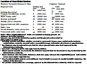 |
|
FIGURE 13.37 ■ Location of gray water system. (Courtesy of International Code Council, Inc. and the International Plumbing Code 2000)
|
|
GRAY WATER SYSTEMS
FIGURE 13.38 ■ Design criteria of six typical soils. (Courtesy of International Code Council, Inc. and the International Plumbing Code 2000)
|
Design Criteria of Six Typical Soils
|
Minimum square meters
|
Maximum absorption
|
|
of Irrigation/leaching
|
capacity in liters
|
|
area per liter of
|
per square meter of
|
|
Type of Soil
|
estimated graywater
|
irrigation/leaching area
|
|
discharge per day
|
for a 24-hour period
|
|
Coarse sand or gravel
|
0.005
|
203.7
|
|
Fine sand
|
0.006
|
162.9
|
|
Sandy loam
|
0.010
|
101.8
|
|
Sandy clay
|
0.015
|
692
|
|
Clay with considerable sand or gravel
|
0.022
|
44.8
|
|
Clay with small amounts of
|
|
|
sand or gravel
|
0.030
|
32.6
|
|
FIGURE 13.39 ■ Design criteria of six typical soils. (Courtesy of International Code Council, Inc. and the International Plumbing Code 2000)

|
|
|
RATES OF RAINFALL FOR VARIOUS CITIES
Rainfall raics, in inches per hour, are based on в storm of one-hour duration and a 100-year return period. The nun fill rales shown in the appendix are derived from Figure 11061
|
|
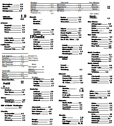 |
|
FIGURE 13.40 ■ Rates of rainfall. (Courtesy of International Code Council, Inc. and the International Plumbing Code 2000)
|
|
|
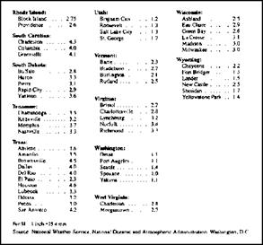
FIGURE 13.40 ■ (Continued) Rates of rainfall. (Courtesy of International Code Council, Inc. and the International Plumbing Code 2000)
|
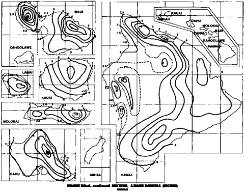
For SI; 1 inch з 25.4 mm.
Source: Nation*! Weather Service, National Oceanic and Atmospheric Administration, Washington. DC.
FIGURE 13.41 ■ Hawaii figures show a 100-year, one – hour rainfall rate. (Courtesy of International Code Council, Inc. and the International Plumbing Code 2000)
|
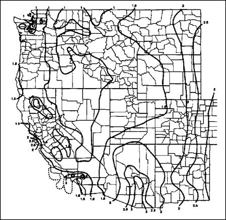
FIGURE 13.42 ■ Chart of the western United States shows a 100-year, one-hour rainfall rate. (Courtesy of International Code Council, Inc. and the International Plumbing Code 2000)
|
|
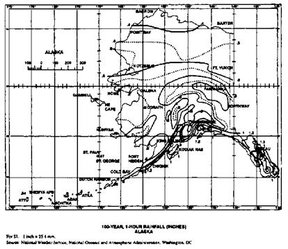
FIGURE 13.43 ■ Alaska’s 100-year, one-hour rainfall rate (Courtesy of International Code Council, Inc. and the International Plumbing Code 2000)
|
|
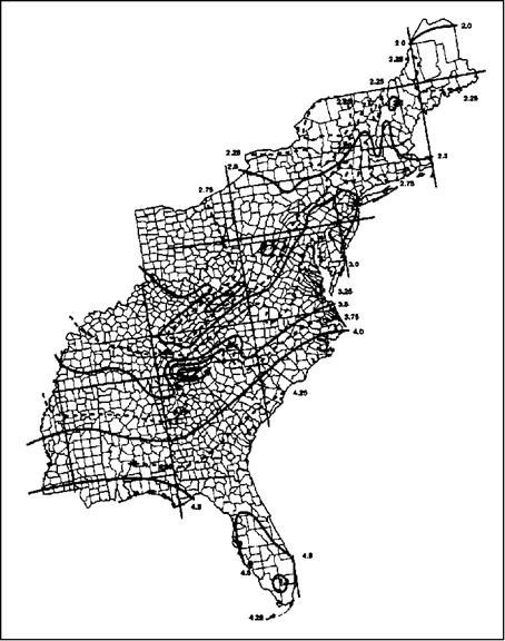
FIGURE 13.44 ■ 100-year, one-hour rainfall rate for the eastern United States. (Courtesy of International Code Council, Inc. and the International Plumbing Code 2000)
|
|
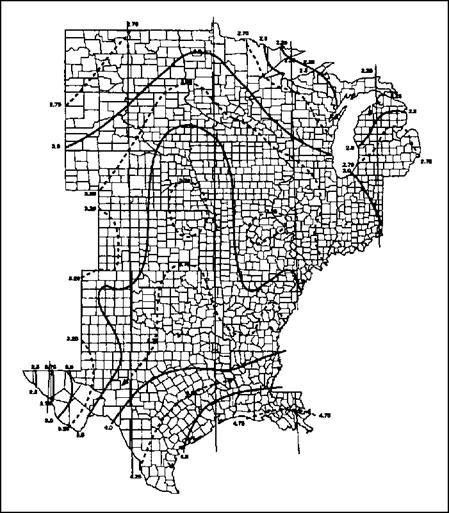
FIGURE 13.45 ■ 100-year, one-hour rainfall rate for the central United States. (Courtesy of International Code Council, Inc. and the International Plumbing Code 2000)
|
 |
|
|
|
SIZE OF VERTICAL CONDUCTORS AND LEADERS
|
DIAMETER OF LEADER ОпсЬмУ*
|
HORIZONTALLY PROJECTED ROOF AREA (square (Mt)
|
|
Rainfall rat* (inch** par tour)
|
|
1
|
2
|
3
|
4
|
5
|
8
|
7
|
8
|
9
|
10
|
11
|
12
|
|
2
|
2.880
|
1,440
|
960
|
720
|
575
|
480
|
410
|
360
|
320
|
290
|
260
|
240
|
|
3
|
8,800
|
4,400
|
2,930
|
2,200
|
1,760
|
1,470
|
1,260
|
1,100
|
980
|
880
|
800
|
730
|
|
4
|
18,400
|
9,200
|
6,130
|
4,600
|
3,680
|
3,070
|
2,630
|
2,300
|
2,045
|
1,840
|
1,675
|
1,530
|
|
5
|
34,600
|
17,300
|
11,530
|
8,650
|
6,920
|
5,765
|
4,945
|
4,325
|
3,845
|
> 3.460
|
3,145
|
2,880
|
|
6
|
54,000
|
27,000
|
17,995
|
13,500
|
10,800
|
9,000
|
7,715
|
6,750
|
6,000
|
5,400
|
4,910
|
4,500
|
|
8
|
116,000
|
58,000
|
38,660
|
29,000
|
23,200
|
19,315
|
16,570
|
14,500
|
12,890
|
11,600
|
10,545
|
9,660
|
For SI: 1 inch = 25.4 mm, 1 square foot – 0.0929 m2.
a. Sizes indicated are the diameter of circular piping. This table is applicable to piping of other shapes provided the cross – sectional shape fully encloses a circle of the diameter indicated in this table.
|
|
|
8QE OF
|
HOCUZOKTALLY PROJECTED ROOF AREA (*qu*#• fMt)
|
|
HORIZONTAL
|
ЯаілМІ rata (Inch— par hour)
|
|
flnehaa)
|
1
|
*
|
*
|
«
|
»
|
Г
|
|
f% unit vertical in 12 units horizontal (1-percent slope)
|
|
3
|
3.288
|
1.644
|
1,096
|
822
|
657
|
548
|
|
4
|
7.520
|
3,760
|
2,506
|
1,800
|
1.504
|
1.253
|
|
5
|
13,360
|
6,680
|
4,453
|
3,340
|
2,672
|
2,227
|
|
6
|
21,400
|
10,700
|
7,133
|
5.350
|
4.280
|
3,566
|
|
8
|
46,000
|
23,000
|
15,330
|
11,500
|
9.200
|
7,600
|
|
30
|
82,800
|
41,400
|
27.600
|
20,700
|
16.580
|
13,800
|
|
12
|
133,200
|
66,600
|
44,400
|
33,300
|
26,650
|
22,200
|
|
15
|
218,000
|
109.000
|
72,800
|
59,500
|
47,600
|
39,650
|
|
/4 unit vertical in 12 units horizontal (2
|
percent slope)
|
|
3
|
4.640
|
2.320
|
1,546
|
1,160
|
928
|
773
|
|
4
|
10,600
|
5,300
|
3,533
|
2,650
|
2,120
|
1,766
|
|
5
|
18,880
|
9,440
|
6,293
|
4,720
|
3,776
|
3,146
|
|
6
|
30,200
|
15,100
|
10,066
|
7,550
|
6,040
|
5,033
|
|
8
|
65,200
|
32,600
|
21,733
|
16,300
|
13,MO
|
10,866
|
|
10
|
116,800
|
58,400
|
38.950
|
29,200
|
23,350
|
19,450
|
|
12
|
188,000
|
94,000
|
62,600
|
47,000
|
37,600
|
31,350
|
|
15
|
336,000
|
168.000
|
112,000
|
84,000
|
67,250
|
56,000
|
|
/2 unit vertical in 12 units horizontal (4-percent slope)
|
|
3
|
6.576
|
3.288
|
2,295
|
1,644
|
1,310
|
1,096
|
|
4
|
15,040
|
7.520
|
5.010
|
3,760
|
3,010
|
2,500
|
|
5
|
26,720
|
13.360
|
8,900
|
6,680
|
5,320
|
4.450
|
|
6
|
42,800
|
21,400
|
13,700
|
10,700
|
8,580
|
7,140
|
|
*
|
92,000
|
46,000
|
30,650
|
23,000
|
18,400
|
15,320
|
|
10
|
171,600
|
85,800
|
55,200
|
41,400
|
33,150
|
27.600
|
|
12
|
266.400
|
133,200
|
88.800
|
66,600
|
53,200
|
44.400
|
|
15
|
476.000
|
238,000
|
158,800
|
119,000
|
95,300
|
79.250
|
|
For Si: 1 inch = 25.4 mm, I square foot *» 0.0929 m2,
|
 FIGURE 13.47 ■ Size of horizontal storm drainage piping. [Courtesy of International Code Council, Inc. and the International Plumbing Code 2000)
|
Sizing Of Horizontal Rainwater Piping
|
|
|
Size of
|
Flow at
|
Maximum Allowable Horizontal Proluttd Root Ann
|
|
|
РІР»,
|
imVTL Slope,
|
|
Square Feet at Various Rainfall Rates
|
|
|
tnchee
|
flpm
|
1"Лг
|
2"/hr
|
3Vhr
|
4‘/h r
|
5-/hr
|
B-ffir
|
|
3
|
34
|
3288
|
1644
|
1096
|
022
|
657
|
548
|
|
4
|
78
|
7520
|
3760
|
2506
|
1880
|
1504
|
1253
|
|
5
|
139
|
13,360
|
6660
|
4453
|
3340
|
2672
|
2227
|
|
6
|
222
|
21,400
|
10.700
|
7133
|
5350
|
4280
|
3568
|
|
6
|
470
|
46,000
|
23,000
|
15,330
|
11.500
|
9200
|
7670
|
|
10
|
860
|
62.800
|
41,400
|
27,600
|
20,700
|
16.560
|
13.B00
|
|
12
|
1384
|
133,200
|
66.800
|
44,400
|
33.300
|
26,650
|
22 200
|
|
15
|
2473
|
238,000
|
119,000
|
79,333
|
59.500
|
47.600
|
39,650
|
|
9lze of
|
Flow at
|
Maximum Allowable Horizontal Protected Root Araaa
|
|
|
Pip*.
|
1/47П. Slope,
|
|
Square Feet at Various Rainfall Rates
|
|
|
«— * – menu
|
gpm
|
1Vhr
|
2*/hr
|
3“/hr
|
4Vhr
|
5*mr
|
67hf
|
|
3
|
48
|
4640
|
2320
|
1546
|
1160
|
928
|
773
|
|
4
|
110
|
10,600
|
5Э00
|
3533
|
2650
|
2120
|
t766
|
|
5
|
196
|
18,880
|
9440
|
6293
|
4720
|
3776
|
3146
|
|
в
|
314
|
30,200
|
15,100
|
10,066
|
7550
|
6040
|
5033
|
|
8
|
677
|
65,200
|
32,600
|
21,733
|
18.300
|
13.040
|
10.866
|
|
10
|
1214
|
116,800
|
56,400
|
38,950
|
29,200
|
23,350
|
19,450
|
|
12
|
1953
|
188,000
|
94,000
|
62,600
|
47.000
|
37,600
|
31.360
|
|
15
|
3491
|
336 000
|
168.000
|
112,000
|
84,000
|
87.250
|
56.000
|
|
Size of
|
Flow at
|
Maximum Allowable Horizontal Projected Roof Areas
|
|
|
P»P*
|
V2-/TL Slope,
|
|
Square Feat at Varioue Rain tall Rataa
|
|
|
Inchee
|
flpm
|
IVhr
|
2"/hr
|
3Vhr
|
4"/hr
|
57hr
|
•Vhr
|
|
3
|
68
|
6576
|
3288
|
2192
|
1844
|
1310
|
1096
|
|
4
|
156
|
15,040
|
7520
|
5010
|
3760
|
3010
|
2500
|
|
5
|
278
|
26,720
|
13,380
|
8900
|
8680
|
5320
|
4450
|
|
e
|
446
|
42,800
|
21,400
|
14,267
|
10.700
|
8560
|
7140
|
|
8
|
956
|
92,000
|
46,000
|
30,650
|
23,000
|
1B.400
|
15,320
|
|
10
|
1721
|
165,600
|
82,800
|
55.200
|
41,400
|
33.150
|
27.600
|
|
12
|
2766
|
266,400
|
133,200
|
68,800
|
66,600
|
53,200
|
44,400
|
|
16
|
4946
|
476,000
|
238,000
|
158,700
|
119,000
|
95,200
|
79,300
|
|
|
|
1, The аігіпд data for horizontal piping la baaed on the pip*» flowing full.
2, For ralnfal rat#* otter than thoe# listed, determine (he allowable roof area by dividing the area giver in the 1 Inch/hour (25 mm/hour) column by the desired ralnfal rate
|
|
|
FIGURE 13.48 ■ Sizing of horizontal rainwater piping. (Courtesy of International Code Council, Inc. and the International Plumbing Code 2000)
|
|
|
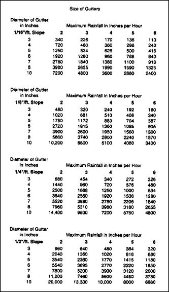
FIGURE 13.49 ■ Size of gutters. (Courtesy of International Code Council, Inc. and the International Plumbing Code 2000)
|
 |
|
SIZE OF SEMICIRCULAR ROOF GUTTERS
|
DIAMETER
OF GUTTERS (Inch**}
|
HORIZONTALLY PROJECTED ROOF AREA (tqwi f**t)
|
|
RAWFALL RATE (Inch** p*r hour}
|
|
1
|
»
|
|
*
|
*
|
•
|
|
|
6 unit vertical in 12 units horizontal (0.5-percenl slope)
|
|
|
|
3
4
5
6
7
8
10
|
680
1.440
2.5O0
3.840
5.520
7.960
14.400
|
340
720
1,250
1,920
2.760
3.980
7,200
|
226
480
834
1,280
1,840
2,655
4.800
|
170
360
625
960
1,380
1,990
3,600
|
136
288
5O0
768
1.100
1.590
2.880
|
113
240
416
640
918
1.325
2.400
|
|
/g unit vertical in 12 units horizontal (1 – percent slope)
|
|
3
|
960
|
480
|
320
|
240
|
192
|
160
|
|
4
|
2.040
|
1,020
|
681
|
510
|
408
|
340
|
|
5
|
3.520
|
1,760
|
1,172
|
880
|
704
|
587
|
|
6
|
5.440
|
2.720
|
1,815
|
1.360
|
1.085
|
905
|
|
7
|
7,800
|
3,900
|
2,600
|
1,950
|
1,560
|
1,300
|
|
S
|
11.200
|
5,600
|
3,740
|
2,800
|
2.240
|
1,870
|
|
10
|
20.400
|
10,200
|
6,800
|
5,100
|
4,080
|
3,400
|
|
U unit vertical in 12 units horizontal (2-percent slope)
|
|
3
|
1.360
|
680
|
454
|
340
|
272
|
226
|
|
4
|
2.880
|
1,440
|
960
|
720
|
576
|
480
|
|
5
|
5.000
|
2,500
|
1,668
|
1,250
|
1,000
|
834
|
|
6
|
7.680
|
3,840
|
2,560
|
1,920
|
3.536
|
1.280
|
|
7
|
11,040
|
5,520
|
3,860
|
2,760
|
2,205
|
1,840
|
|
8
|
15.920
|
7,960
|
5,310
|
3,980
|
3.180
|
2.655
|
|
10
|
28,800
|
14.400
|
9,600
|
7,200
|
5,750
|
4,800
|
|
/2 unit vertical in 1
|
units horizontal (4-percent slope)
|
|
3
|
1,920
|
960
|
640
|
480
|
384
|
320
|
|
4
|
4,080
|
2,040
|
1,360
|
1,020
|
816
|
680
|
|
5
|
7,080
|
3,340
|
2.360
|
1,770
|
1.415
|
1,180
|
|
6
|
11.080
|
5.540
|
3.695
|
2,770
|
2.220
|
1,850
|
|
7
|
15.600
|
7,800
|
5,200
|
3,900
|
3,120
|
2,600
|
|
8
|
22,400
|
11,200
|
7,460
|
5,600
|
4,480
|
3,730
|
|
10
|
40,000
|
20,000
|
13,330
|
10,000
|
8,000
|
6,560
|
For St: 1 inch = 25.4 пип. I squire fool * 0.0929 m2.
|
|
FIGURE 13.50 ■ Size of semicircular roof gutters. (Courtesy of International Code Council, Inc. and the International Plumbing Code 2000)
|
Inches
|
(mm)
|
Inches
|
(mm)
|
|
Flat
|
(Flat)
|
3
|
(76)
|
|
2
|
(51)
|
4
|
(102)
|
|
4
|
(102)
|
5
|
(127s)
|
|
6
|
(152)
|
6
|
(152)
|
|
Controlled Flow Maximum Roof Water Depth Roof Rise,* Max Water Depth at Drain,
|

FIGURE 13.51 ■ Controlled flow maximum roof water depth. (Courtesy of international Code Council, Inc. and the international Plumbing Code 2000)
The visual graphics here should serve you well in your career. Knowing and understanding your local code is very important, so spend time with your codebook to gain a complete understanding of your local codes. Keep in mind that the information in this chapter is based in the International Code. If you work with the Uniform code, you may discover some differences between local requirements and those shown here.
This page intentionally left blank.


![]()
![]()


 Sizing load based on design criteria.
 FIGURE 13.16 ■ Maximum unit loading and maximum length of drainage and vent piping. (Courtesy of International Code Council, Inc. and the International Plumbing Code 2000)
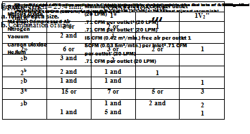


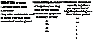


![]() FIGURE 13.47 ■ Size of horizontal storm drainage piping. [Courtesy of International Code Council, Inc. and the International Plumbing Code 2000)
FIGURE 13.47 ■ Size of horizontal storm drainage piping. [Courtesy of International Code Council, Inc. and the International Plumbing Code 2000)


Leave a reply