Tunnel Liner Plates and Rib and Lagging
Steel tunnel liner plate and steel rib and lagging are flexible structures placed by a tunneling operation. Like other flexible structures, they are designed to deflect vertically under load so that the lateral side pressure will be established and essentially uniform radial pressure will develop about the perimeter of the structure. Because these structures are used in tunneling operations, however, under most circumstances it is not necessary to design for the complete prism load. The AASHTO Standard
|
TABLE 5.27 Average Values of Modulus of Soil Reaction E’ for Deflection Calculations for Flexible Pipe
|
Conversion: 1 lb/in2 = 6.895 X 10 3 MPa.
Note: Values applicable only for fills less than 50 ft (15 m). Table does not include any safety factor. For use in predicting initial deflections only; appropriate deflection lag factor must be applied for long-term deflections. If bedding falls on the borderline between two compaction categories, select lower E’ value or average the two values. Percentage Proctor based on laboratory maximum dry density from test standards using about 12,500 ft – lb/ft3 (598,000 J/m3) (ASTM D698, AASHTO T-99, USBR Designation E-11). 1 lb/in2 = 6.9 kN/m2.
*ASTM designation D2487, USBR designation E-3.
fLL = liquid limit.
$Or any borderline soil beginning with one of these symbols (i. e., GM-GC, GC-SC).
§For ±1% accuracy and predicted deflection of 3%, actual deflection would be between 2% and 4%.
Source: From American Society of Civil Engineers, J. Geotech. Eng. Div., January 1977, pp. 33-43,
with permission. (Based on Amster K. Howard, “Soil Reaction for Buried Flexible Pipe,” U. S. Bureau of Reclamation, Denver, Colo.)
|
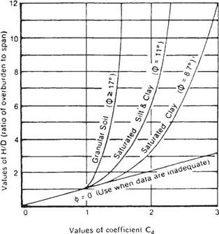
FIGURE 5.41 Diagram for coefficient Cd for load calculations for tunnels. ф is soil friction angle. (From Standard Specifications for Highway Bridges, American Association of State Highway and Transportation Officials, Washington, D. C., 2004, with permission) |
Specifications for Highway Bridges state that the earth pressure on a tunnel liner can be determined from the following equation:
W£ = CdlyS (5.56)
where WE = earth pressure at the crown, kip/ft2
Cdt = load coefficient for tunneling (from Fig. 5.41)
7 = unit weight of soil, kip/ft3 S = tunnel diameter or span, ft
The tunnel liners act in compression caused by ring thrust. If a structural member with significant stiffness is used, the effects of ring flexure must be included because the flexural stress may reduce the capacity of the member to carry load.
The design of tunnel liners generally consists of designing the liner for joint strength, wall buckling, and minimum stiffness for installation. The analysis of steel ribs with lagging is a fairly straightforward procedure. The steel ribs are generally placed at 4-ft (1.2-m) intervals on centers. The lagging must carry the load between these and is designed for moment and shear over the 4-ft (1.2-m) span. The load per linear foot may be taken as that for tunnel liner plate. The ribs must be designed to withstand the load transferred from the lagging. The stress in the steel ribs should include the effects of both flexure and thrust. The use of precast concrete tunnel liners as an initial support is
rare. The analysis is complex, but may be aided by the use of moment-thrust interaction diagrams. (See Standard Specifications for Highway Bridges, AASHTO; R. V. Proctor and T. L. White, Earth Tunneling with Steel Supports, Commercial Shearing, Inc., 1977; and T. D. O’Rourke, Guidelines for Tunneling Design, ASCE, 1984.)


Leave a reply