STRUCTURAL DESIGN OF DRAINAGE PIPES
The structural capacity of an underground structure and the methods of determining that capacity are dependent upon the material properties of the structure and its physical configuration. In this context, the structure is the composite structure comprised of the pipe and the surrounding soil. The surrounding soil is generally referred to as the soil envelope, and buried structures rely upon the soil envelope for their ability to withstand loads.
Under load, the pipe will deflect laterally and mobilize the passive resistance of the surrounding soil. Also, the pipe and surrounding soil will settle and the pipe will deflect to varying degrees. The relative movement of the pipe and soil results in the stiffer component attracting load and the less stiff component shedding load. This phenomenon is called soil-arching and is a fundamental consideration in the pipe-soil system. A study of the soil-structure interaction is necessary for an adequate solution to the buried structure problem.
Pipes are generally classified as either rigid or flexible, depending on their bending stiffness. For a round pipe under load without the benefit of the soil envelope, deflection due to bending is proportional to D^/EI, where D is the diameter, E is the modulus of elasticity, and I is the moment of inertia of the wall cross-section. EI is the wallbending stiffness. Concrete and clay pipe usually have a relatively thick wall and a high bending stiffness, and are referred to as rigid pipe. Corrugated metal pipe and plastic pipe have much thinner walls and lower bending stiffness, and are referred to as flexible pipe. Any discussion of the structural capacity of the pipe must also discuss whether the pipe is flexible or rigid (these are the only two options), since the design methods for each vary significantly.
Rigid pipe, unless designed by the empirical D-load method, is designed for moment, thrust, and shear. Corrugated metal pipes can generally be designed for thrust alone. Plastic pipes are designed for thrust, deflection, and bending stress and strain.
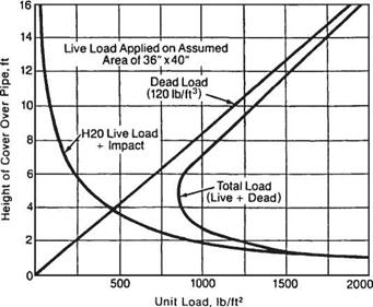
The combination of dead and live loads causes variable pressures on the installed pipe. As illustrated in Fig. 5.29, the dead load pressure increases with an increase in cover height, whereas the live load decreases with an increase in cover height. For highway loads, this results in a minimum load on the structure when there is approximately 4 to 5 ft (1.22 to 1.52 m) of cover. Standard designs for underground structures may be found in industry publications with minimum and maximum cover heights indicated. However, when a structure is designed for a site-specific cover height, the designer should be aware that future changes in roadway elevation may cause increased loading conditions.
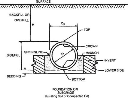
Figure 5.30 shows the nomenclature generally used for culvert design and installation. The supporting soil beneath the culvert is the foundation, and the bedding is that
|
FIGURE 5.29 Design pressures for metal culverts under earth dead load and H 20 highway live load. Conversions: 1 ft = 0.305 m, 1 lb/ft2 = 0.0479 kPa. (From Handbook of Steel Drainage and Highway Construction Products, American Iron and Steel Institute, 1994, with permission) |
|
FIGURE 5.30 Pipe installation terminology. (From Design Data 40, American Concrete Pipe Association, 1992, with permission) |
portion of the foundation in contact with the bottom of the pipe. The springline of the pipe is located at the location of maximum span. For a circular or elliptical pipe, this occurs at midheight. The haunch is the zone between the springline and the invert. The soil placed and compacted around the culvert is known as the backfill, or sometimes as the sidefill. The bedding and backfill are collectively referred to as the embedment.
In 1997 AASHTO published the first edition of the LRFD Bridge Design Specifications, and in 2007 the fourth edition. The goal of AASHTO is to use only the LRFD design code for new construction. However, the more traditional methods are currently more widely used for pipe design.


Leave a reply