Size Determination for Culverts with Outlet Control
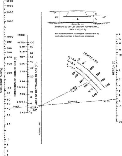
The headwater depth for a culvert operating under outlet control may be determined with the aid of the outlet control nomographs in HDS 5. An example of these nomographs for box culverts is shown in Fig. 5.15. The following procedure may be used to determine the head H from the nomographs. The length L (ft), entrance coefficient ke, and design discharge must be known. Locate L on the appropriate ke curve, and connect this point with the proposed culvert size. Locate the design discharge and extend a line from that point through the turning point intersection of the previous line to read the
|
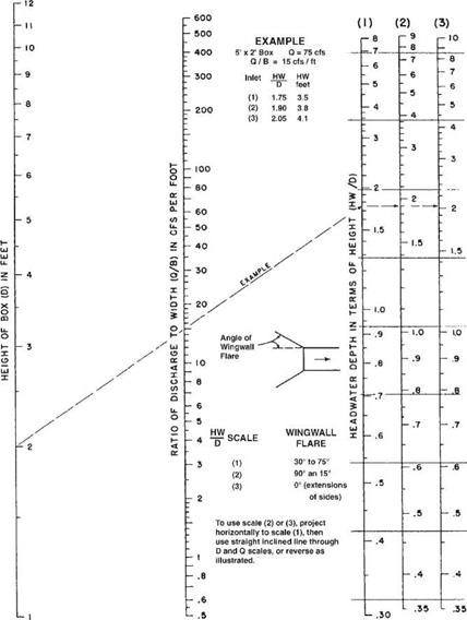
FIGURE 5.14 Flow nomograph for box culvert under inlet control. (From “Hydraulic Design of Highway Culverts," HDS 5, FHWA, with permission) |
value of the head H (ft) on the right. For example, assume L = 306 ft, ke = 0.5, a 2-ft X 2-ft box, and Q = 40 ft3/s. The nomograph shows that H = 7.3 ft. The headwater depth, HW, may then be determined by geometry from the equation
|
FIGURE 5.15 Flow nomograph for box culvert under outlet control with n = 0.012. (From "Hydraulic Design of Highway Culverts," HDS 5, FHWA, with permission) |
where the terms are defined by the inset figure in the nomograph. (Note: To use the chart with SI units, first convert from SI units to U. S. Customary units—1 ft = 0.305 m, 1 ft2 = 0.0929 m2, 1ft3/s = 0.0283 m3/s). Where the outlet is submerged, ho is equal to the tail – water depth just downstream of the outlet and may be calculated from Manning’s equation as applied to the channel. Where the outlet is not submerged, ho is equal to the greater of the tailwater depth or one-half of the sum of the culvert height plus the critical depth, (dc + D)/2. By examining different alternatives, a culvert can be selected that provides the required flow within the allowable headwater depth.


Leave a reply