Single-Lane Ramp Terminals
A ramp terminal is the portion of a ramp adjacent to the through lane on the mainline. It includes both the taper and the speed-change lane. Ohio has recently revised its terminal criteria and uses two basic terminal classifications:
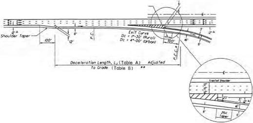
High-speed terminals are intended for use on all facilities with a design speed of 50 mi/h (80 km/h) or higher. They are used in both rural and urban locales. Figure 2.41 shows the details for high-speed single-lane entrance terminals. This terminal is a taper-type design for the last 1250 ft (381 m), tapering from a 25-ft (7.6-m) offset from the mainline to zero. Tables A and B in Fig. 2.41 provide information for designing the length of the terminal to provide adequate distance for entering vehicles that matches or nearly matches the design speed of the mainline. This must be achieved by the time the terminal narrows to 12 ft (3.7 m) in width (see Fig. 2.41). Figure 2.42 provides design information for high-speed single-lane exit terminals that are used in both rural and urban locales. In the urban environment, a sharper departure curve is permitted for the exit curve, which allows for a slower speed exit. Once again, Tables A and B are provided in Fig. 2.42 to determine the proper terminal length based on mainline speed, first curve speed, and vertical grade adjustment.

* lanijth Stay За fncraassd Far Sup*rm ft *o т гол Transition +* To Do tor mint Lp. Sub f roc t is Ana Lt Fro» i„
* + + ІЛаШіпа pawad shouldtr width os rtqvi’td by
![]()
л*о r*j For Si/ufft Ian* £t1raoct Тагмілаіш
L Tht minimum accolorotiaa tangth* і &ho! t b* It *■ Lt.
2. Tht 9r to 2У woriab/t rid lb of trtoftd shootdar of Ihs *n franco tor mine I stroll bt s/apsd for 12′ as raqvirtd for яоіпііщ da sign /у*иоііу j£jm. Sft+l tectpt (or tha tost /00′ to 200′ at ths 9′ and. which It to b* stopmd os rtparrtd for praptr tarm/not grading.
X Normally sing ft font romps *гШ ho r# о width pf t6 Ths width shat! bo incr+ostd to whan th r romp гв^у)
is lass than 200′. ШЬ»л an /S’ w ids romp »j mod. ths 25* oatroac-щ tarminot width shaft to rtfoinad and th* 9‘ width rodvcod by 2*.
A. if tp tparoflol isngtht is not ropairod H f- S50*L than th» 2QQ" minimum spiral shootd b* tango* t to ths SOft Гарт
|
Uo in line Design Speed. V (mph) |
Acceleration length, L (ft) for design speed of lost romp curve, Vr (mph) |
||||||||
|
Stop |
IS |
20 |
25 |
30 |
35 |
40 |
45 |
50 |
|
|
SO |
720 |
660 |
610 |
550 |
450 |
350 |
130 |
– |
– |
|
55 |
960 |
900 |
810 |
780 |
670 |
550 |
320 |
150 |
– |
|
60 |
1200 |
1140 |
1100 |
1020 |
910 |
800 |
550 |
420 |
180 |
|
65 |
1410 |
І350 |
1310 |
1220 |
1120 |
1000 |
770 |
600 |
370 |
|
70 |
1620 |
1560 |
1520 |
1420 |
1350 |
1230 |
1000 |
820 |
580 |
|
TABLE B High-speed entrance terminal adjustment factors as a function of grade
No adjustment required for grades less than 3X. |
* Ratio from this table multiplied by acceleration length inTobfeA gives occeierotion length on grade.
The ‘’grade" in the table is the overage grade measured over the distance for which the occe ter at ion length applies.
FIGURE 2.41 High-speed single-lane entrance terminal. Conversions: 1 mi/h = 1.609 km/h, 1 ft = 0.305 m. (From Location and Design Manual, Vol. 1, Roadway Design, Ohio Department of Transportation, with permission) (Continued)
• • The Угпітит Deceleration Length, L, After Adjustment for Gradet
![]()
![]()
![]()


Table B, S^xj// Be 600′
• •• Or Other Design Speed Li/nitlnq Geometric Control Such As The Stopping
Sight Distance for A Vertical Ctxve Or The воск Of A Traffic Oueoe.
* uainline paved shoulder width os retired by ТсЫе 2.22 Of 223.
Notes for Single-Lone Exit Terminals
1. The Exit Cirve should nor mol I у be Г-JO’ (RuroU or 49-00′ (Jr bon) where The mainline is on Tangent. Where the mainline is on curving alignment, the maximum differential between the Exit Curve and the mcinline curve should normally
be f-JO’ iRuroll or 49-00‘ IUrbant. This differential. however, moy vary by as much os one degree in order to
ovoid a tangent exit oligrvr>ent. (See Section SOJ.6.4 for The oliowoble tronsverse breaks in superelevation cross-slope.>
2. When the First Ramp Curve does not exceed в9, the Exit Curve moy be compounded directly with the first Romp Ciwe ot a RCC КЮ’ beyond the nose. When the first Ramp Curve does exceed 69, c spiral should be placed between the Exit Curve and the first Ramp Curve and the beginning of the spiral (CS) should be ot the nose.
J. Normally single lone romps will hove a width of (S’. The width shall be increased to Ш’ when the ramp rod>us is lass than 200′. when an I6‘ wide romp Is used, the J9′ exit Terminal width shall be retained and the 2J’ width reduced by 2‘.
|
Mo in line Design Speed. V (mph) |
Deceleration length, L (ft) for design speed of first ramp curve, Vr (mph) *** |
||||||||
|
Stop |
15 |
го |
25 |
30 |
35 |
40 |
45 |
50 |
|
|
50 |
435 |
405 |
385 |
355 |
315 |
265 |
225 |
175 |
– |
|
55 |
460 |
455 |
440 |
410 |
380 |
350 |
285 |
235 |
– |
|
60 |
530 |
500 |
480 |
460 |
430 |
405 |
350 |
300 |
240 |
|
65 |
570 |
540 |
520 |
500 |
470 |
440 |
390 |
340 |
■280 |
|
70 |
615 |
590 |
570 |
550 |
520 |
490 |
440 |
390 |
340 |

0 P. C.C. Or Mid-Point of 200′ Spiro I
00 Th» Minimum Deceltrotion Length, L. After Adjustment For Grode (Table В ) fS BOO*
000 Or Other Design Speed Limiting Geometric Control Such As The Stopping
Sight Distance For A Verticol Curve Or The воск Of A Troffic Queue.
|
TABLE B High-speed exit terminal adjustment factors as a function of grade
No adjustment required for grades less thon 3X. |
* Ratio from this table mult ip tied by dece lerot ion length in Table A gives dece lerot ion length on grade.
The ‘grade" in the toble is the average grade measured over the distance for which the dece lerot ion length applies.
FIGURE 2.42 High-speed single-lane exit terminal. Conversions: 1 mi/h = 1.609 km/h, 1 ft = 0.305 m. (From Location and Design Manual, Vol. 1, Roadway Design, Ohio Department of Transportation, with permission) (Continued)
|
|
 |
|
|
|
|
|
|
|
|

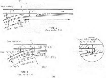
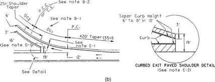
TABLE 2.29 Design Notes for Low-Speed Entrance and Exit Terminals
See Fig. 2.43
A. General
1. Low-speed terminals are intended for use on highways which have little or no access control except through an interchange area. Many of the features of low-speed terminals are applicable to a terminal of one ramp with another ramp in a freeway interchange.
B. Exit terminal
1. The curve differential between the through roadway and exit curve DC1 may vary from a minimum of 4° to the maximum allowable differential.
2. Exit curve DC1 may be either compounded or spiraled into ramp curve Dc2.
C. Entrance terminal: type A and type B
1. Type A is preferred and shall normally be used; however, when a ramp enters as an added lane or as a combined acceleration-deceleration lane, type B may be used if its use would result in a substantial savings in cost (i. e., reduced bridge width).
2. The acceleration lane of type A shall be a uniform taper (35:1) relative to the through pavement edge for either tangent or curving alignment.
3. The curve differential between the through roadway and entrance curve Dc5 of type B shall be 4°.
4. The design of the entrance terminal shall be based on the following:
(a) Ramp curve Dc3 of 8° or less. When the through roadway is on a tangent or a curve to the right, Dc4 shall be a 150-ft-long simple curve of a degree such that the differential between it and the through roadway will not exceed 4°. When the through roadway is on a curve to the left, a 150-ft tangent shall be substituted for Dc 4.
(b) Ramp curve Dc3 greater than 8°. A 150-ft spiral shall be substituted for Dc4.
D. Ramp width
1. Normally, single-lane ramps will have a width of 16 ft. The width shall be increased to 18 ft when the ramp radius is less than 200 ft. When an 18-ft-wide ramp is used, the 35-ft exit and 20-ft entrance terminal widths shall be retained and the 19- and 4-ft widths reduced 2 ft.
E. Treated shoulder
1. The width of the treated shoulders along the speed change lane shall be as shown in Fig. 2.25.
2. If the ramp or through roadway has a curb offset greater than 6 ft (or 3 ft) the greater width shall be used at the terminal. Retain the 19-ft width.
3. The special detail drawings shall apply when the through roadway is curbed.
F. Left side terminals
1. Left side entrance and exits shall be designed similarly to the drawing shown, but of opposite hand.
Conversion: 1 ft = 0.305 m.
Source: Location and Design Manual, Vol. 1, Roadway Design, Ohio Department of Transportation,
with permission.


Leave a reply